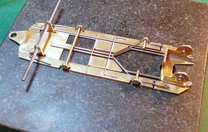
The R-Geo "Toronto" F1 chassis (part one)
Introduction:
This build in itself is pretty simple so there will be a little more explanation and theory in this article. Naturally, if you are bored by that part... just scroll to the pictures.
So... maybe ten days or so ago Rick B tipped me off that he had a new twist on the ubiquitous tuning fork chassis in F1 format. His theory was that the majority of F1 frames are built too stiff in twist flex so he had come up with a simple frame that was showing a lot of promise. He described his design and requested that I do a pictorial when he could get me some parts.
This was really interesting to me because I had built something with the same goal about a year or so ago. Mine had proven enormously successful in its first race but shortly after that it also showed that it could be easily destroyed. After I wrecked that first one beyond repair, I sort of forgot the concept and moved on. Then when Rick mentioned what he was up to, it sounded better and more durable than what I had done.
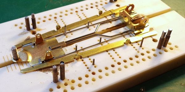
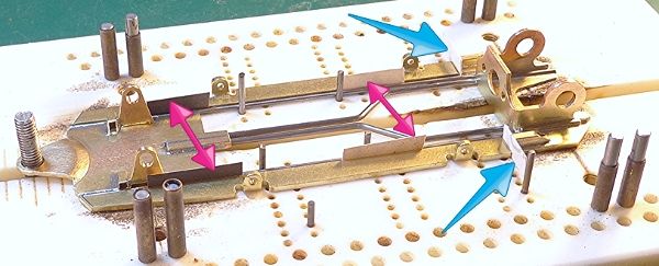
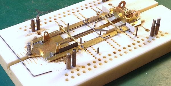
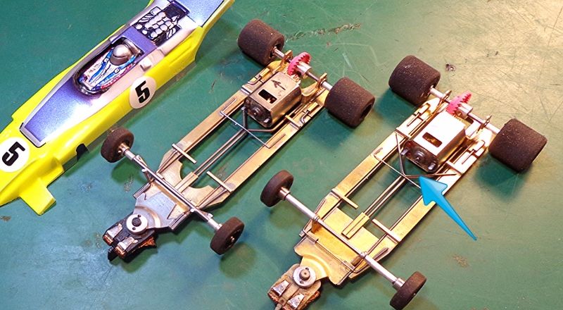
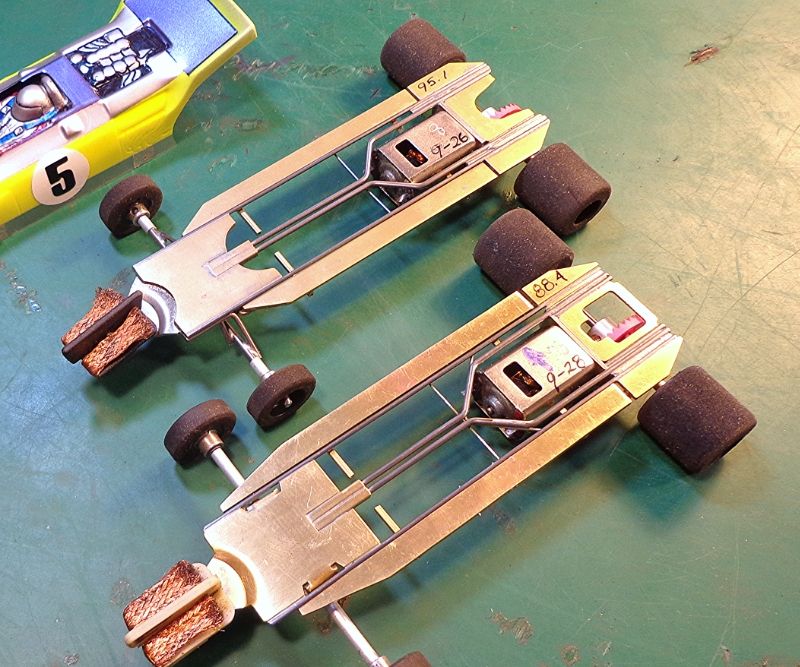
So... while waiting for the parts, I built these two up as a test bed and to make sure that I was on the same page as he was. The one in the foreground is the closest to the description that Rick gave me and it has been tested and tweaked a bit. The one in the background has yet to be tested so it is an unknown and is just shown for reference.
Foreground car:
- R-Geo .050" x 1” nosepiece and bracket.
- .062" tuning forks free in the front tubes.
- Single .047" frame rails.
- .062" x ¼” pans, total weight with body shown and lead wires in place = 88.4 grams.
- Arrow... in the initial build, this ‘V’ shaped stop was two single bits of .047".
- After testing, there was some gear clash sound so I placed the ‘V’ shaped stop of .032" and it was much improved.
On Track:
- In testing on two different speedway tracks in NorCal, this car was very fast.
- This was .015-.020 faster than my best prior speedway cars.
- Surprisingly, this car did not have a “touchy” driving feel like many very light cars.
- I tried it on a flat track and... yeah... it was too light but it was still faster than my standby flat track chassis. It was a little hard to drive... but fast.
- This was pretty inspiring so while the parts were in transit, I tried...
Background car: (not yet tested)
- This car was built to be heavier to start with in order to have a test bed for flat tracks, and will be initially tested without the ‘V’ stop.
- Bracket brace is .062" brass, nosepiece in .062" brass. Pans and rails are the same.
- Total weight all up for this one is just over 95 grams.
- This frame also has a flex stop between the fork rails and main rails just forward of the bracket. This is completely experimental, just something I’m thinking about.
So... on we go...
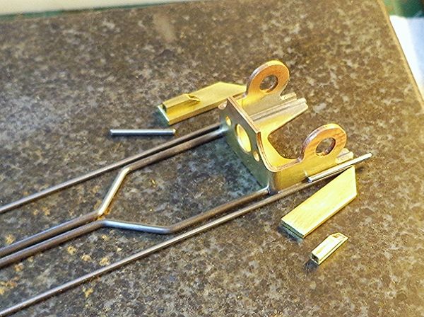
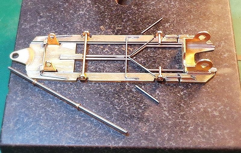
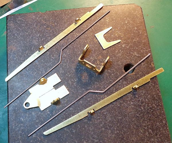
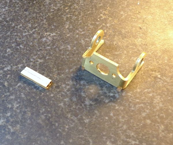
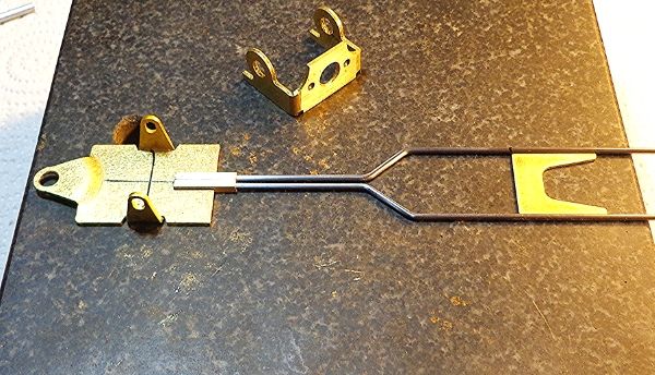
Here are the pre-made parts as you will get them from Rick. You get bracket and nosepiece of .050", pans of .062", bracket brace of .032", and a pair of .062" forks. I have to say that I’ve built a lot of tuning fork chassis and bending and squaring the forks is a serious PITA for me. These forks came very good with very little tuning or squaring required.
Parts:
Baby steps:
- Your first steps should be to detail your bracket and make up your fork tubes.
- Sand or file the bracket face and bottom flat and also the sides if needed.
- Square up the sides to the face, then screw in a test motor and check it again.
- Cut a slot at the bottom of the face as shown for the fork rail to pass through.
- Fork tubes. Two bits of 3/32” box tube soldered up then squared off at about 5/8”.
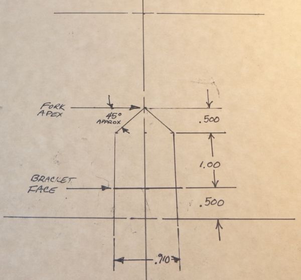
Your guidelines... (the template)
- This is drawn up just to give me some guidelines.
- This one shown here has actual numbers on it and is a reference that I’ll keep.
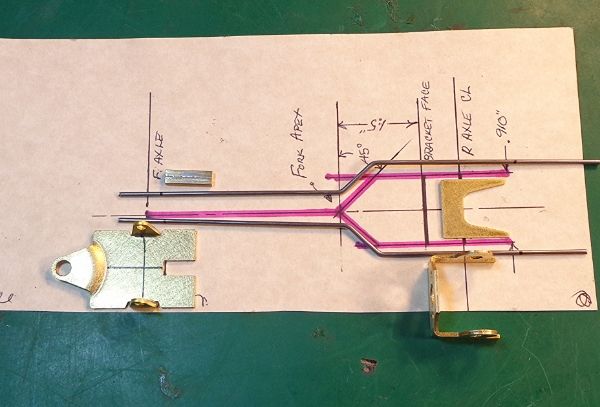
The template in action:
- This template had some mistakes in dimensions so ignore those. I’m just using this one to check angles and alignment.
- This will show how the template is used to lay out your parts and check the lengths.
- Trim your fork wires accordingly and use the template to check parallel.
More template work.
- Lay your forks on a flat surface and make sure they are flat.
- Lay your fork wires on the template to check that the fore and aft legs are parallel.
- Lay your pieces together on a flat block or jig, and check for fit.
- This step is where you’ll find how square your fork rails are.
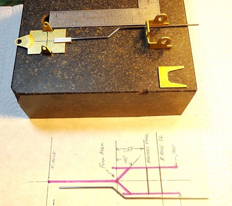
Template gone... all on the flat block:
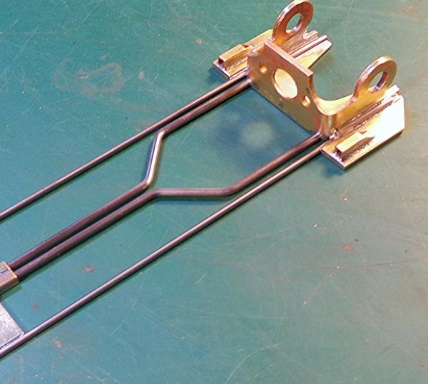
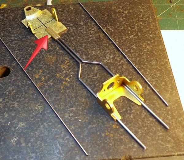
- Now, lay all your parts in place with the forks in the tubes and the bracket brace in place. Check to see that the forks lay as flat as possible while square around the brace.
- Lay the bracket over the sub-assembly. Make sure it slips in place without interference.
- The bends in the wire will want to move things around. Make sure nothing binds.
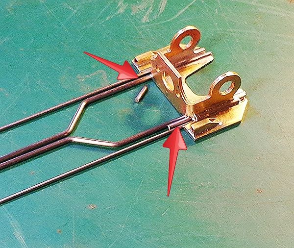
- If all looks flat and square, lightly tack the tubes in place (arrow).
- It is more important for the forks to remain flat at the apex than it is for the tubes at front.
- If the forks are trying to lift the tube assembly a little... that’s OK let it be.
- Remember that in a tuning fork build, the forks should not be forced into a position... let them sit where they want to sit.
Into the jig:
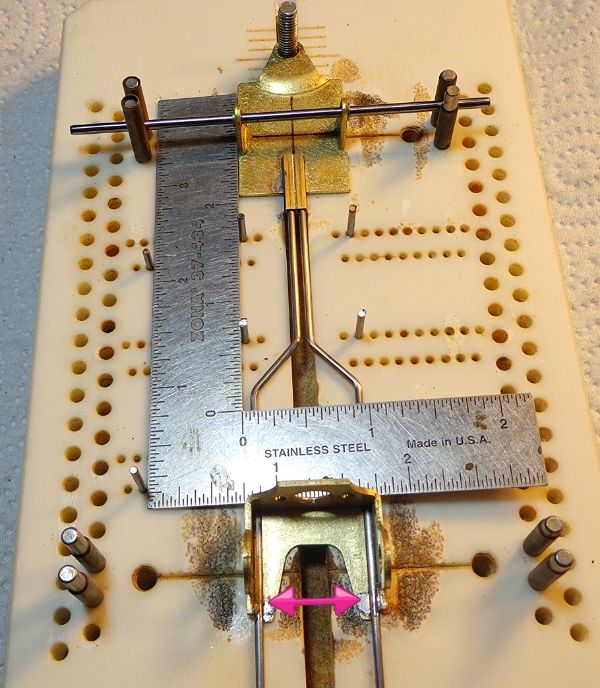
- Place parts in the jig and square up the nosepiece with the guide pin and front axle.
- The axle slots are a little oversized but if you slip a JK 3/32" retainer in the slot, it all fits tight.
- Use a square to align the bracket face square to the chassis.
- Note that there are alignment pins all over the place at this point. Use them a lot.
- Get your bracket at the right spot for your wheelbase (4”).
- I don’t use jig wheels and bearings at this point. It’s more important to square up the bracket face than it is to align the bearing holes perfectly.
- Don't let your bearing holes dictate the accuracy of your bracket face. Align your bearings later.
- When it all looks right, tack your bracket plate and fork rails at the very rear of the bracket (arrow).
Still in the jig:
- Each frame rail is a single .047".
- You can see that I’ve got guide pins all over the place here.
- Your jig and your guide pins will keep you square.
- Lay frame rails in place against the nosepiece, guide pins and bracket.
- Quadruple check the alignment and tack solder the rails at front and back.
Out of the jig... on the flat block.
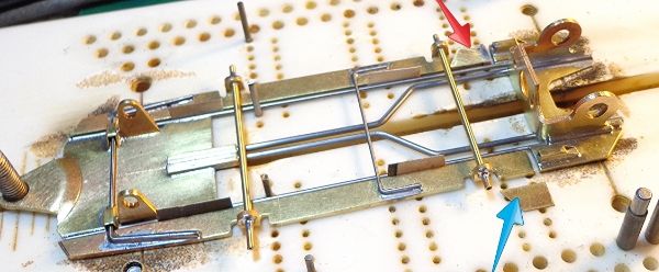
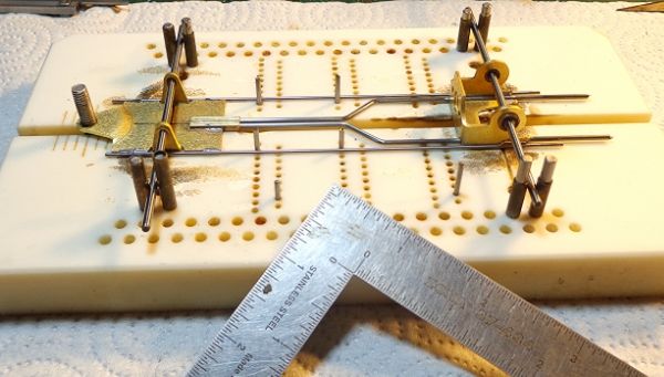
- Here is where you lay your frame on the flat block to check for flatness.
- Clean your chassis up so you can see all your solder joints. Check each one.
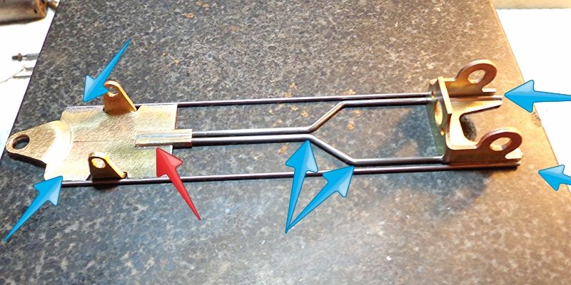
- Check each spot with a blue arrow for flat on the block.
- The apex of your forks may not be perfectly flat but you want very, very close to that.
- Naturally, the forks will be up a little where they go into the tubes, can’t help that.
- Douse the thing with flux, turn on your fan and complete the solder joints.
- Let it cool, then more flux and this time use a torch or a really hot iron and remelt each joint. As you do, check to see if anything moves.
- It’s a good bet that one or more of the joints will “settle” a bit.
- Don’t worry unless something moves dramatically.
- Settling the chassis is key to having a build with no binds in it.
- Don’t be surprised if your tubes (red arrow) move a touch. If the tubes lift a few thou... that’s OK. That is just taking stress or binds off of the forks.
OK... good place to stop for now. Will finish up part 2 tomorrow or the next day.
- Finishing the rear end with a little theory involved.
- Front end, axles, and pan pivots.
- Pan spacing and stops.
- Added weight for minimums or for flat track use.


