


Recently, I have been made aware that certain specific motors, high-timed Group 12 in particular, failed to register counts on deadstrip lap counter systems.
So I have done a little research, and I think I can explain what is going on.
We have all learned in school that when you turn an electric (DC) motor it produces a DC voltage. Certainly if you put a multimeter on it seems that way.
However it turns out the truth is more complicated than that. If you use a scope to measure the waveform generated it looks more like this:
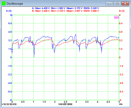
The blue curve is the voltage from the motor, the red is the signal after the LapMaster input filter.
In this instance (Driving a Parma S16D with a Dremel), the motor produces ~3.5 volt, but with small fallout to 0 volt.
This voltage is added to the LapMaster deadstrip voltage of 5 volt, so that the sum is between 5.0 and 8.5 volt.
That is always more than the 3.5 volt which is the minimum required voltage to make LapMaster count.
However when I twist the endbell on this modified motor to simulate higher timing, look what happens:
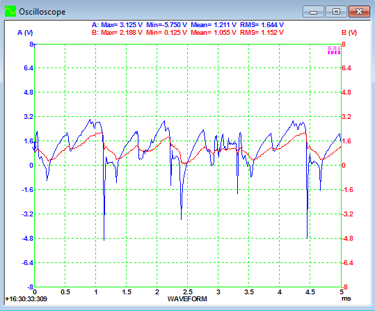
The negative spikes on the blue curve goes much deeper, down to -4.8 volt. The motor is outputting reverse voltage pulses.
Now if you add this to the +5 volt, you only get +0.2 volt, not enough to make a count.
In this meassurement it is only for very brief moments of time, but it is affecting the filtered voltage response as well, dragging it down.
In this case, not enough to be a real problem. But I have not had a change to meassure on the actual troublesome motor.
This is just a simulation. However I think we can conclude that this is the direction the problem is going at.
So what to do about it?
You can boost the deadstrip voltage for a quick fix, but the better solution will be to put a diode in series with the deadstrip wires.
When this is done even a high-timed motor will look like this:
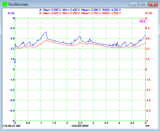
(High-timed motor with diode in series and 3 volt deadstrip voltage.)
Note: The deadstrip voltage should have been 5 volt, but was reduced to keep the meassurement within the scale of the instrument.
Now I have described this in a LapMaster context, but it is really not a problem unique to LapMaster, but something in common for all deadstrip driven counter systems.
Practical fix
My recommendation would be to put a diode (e.g: 1N4001, 1 amp 50 volt - many others would also work), in the deadstrip wire coming from the right side of the dead strip. The marked leg (scribe/circle) should point away from the deadstrip, and towards the counter electronics. You would need one diode for each lane.




