Jump to content


Photo

Basic armature wiring #2


  • Please log in to reply
30 replies to this topic

#1 robbovius

robbovius

    Mid-Pack Racer

  • Full Member
  • PipPipPip
  • 146 posts
  • Joined: 20-March 14
  • Gender:Male
  • Location:MA, USA

Posted 12 January 2016 - 10:01 AM

So, I'm jumping into the deep end here. I've got a selectionn of dead armatures (from that pile of old Ebay motors in another thread) and I'm going to rewind a couple of them, and see what happens. My goals are simple - a running motor - or two - that will push a slot car down the track.


It also seems that I'm collecting 36D parts, and so I figured I'd start on one of those.


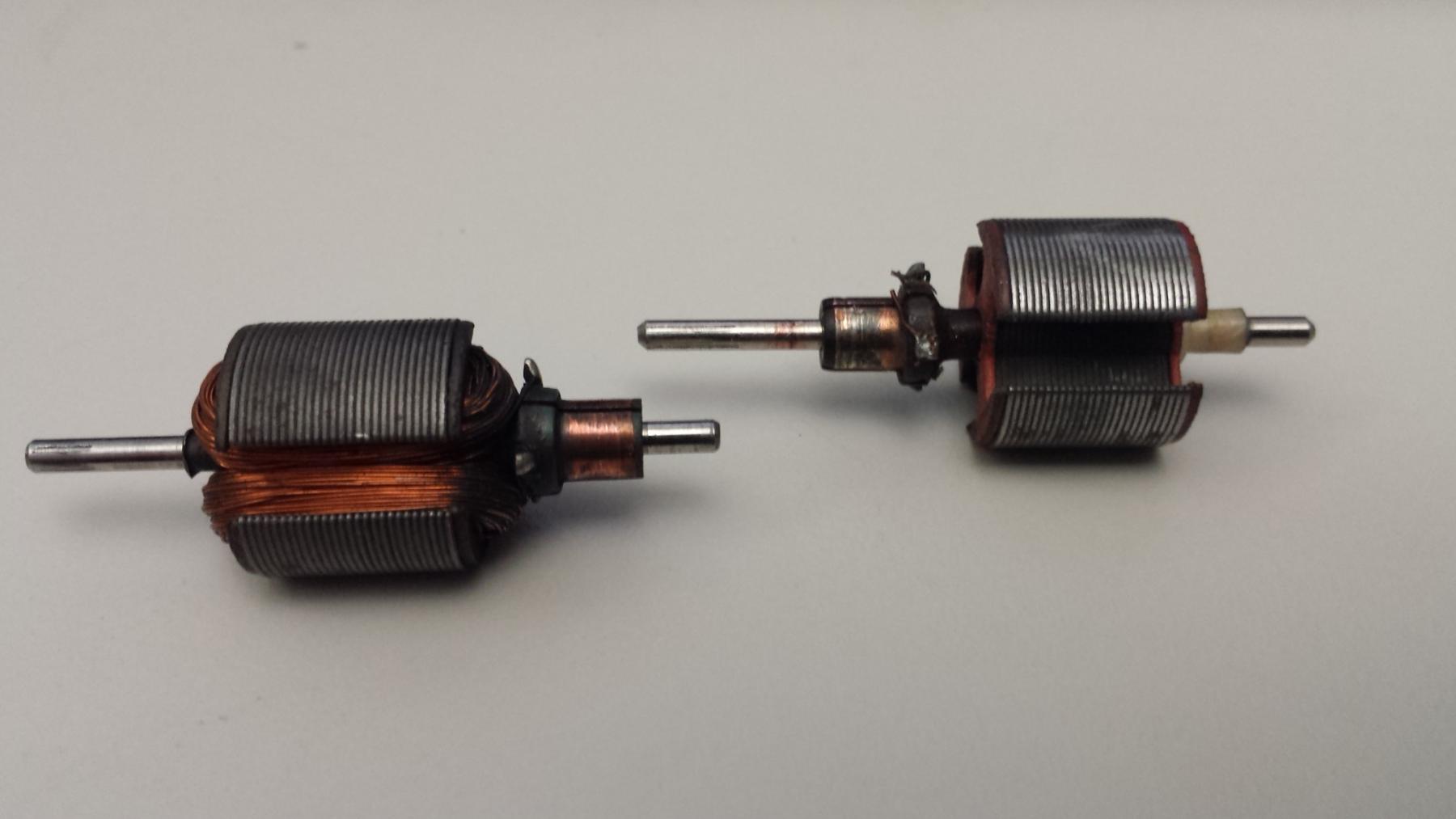
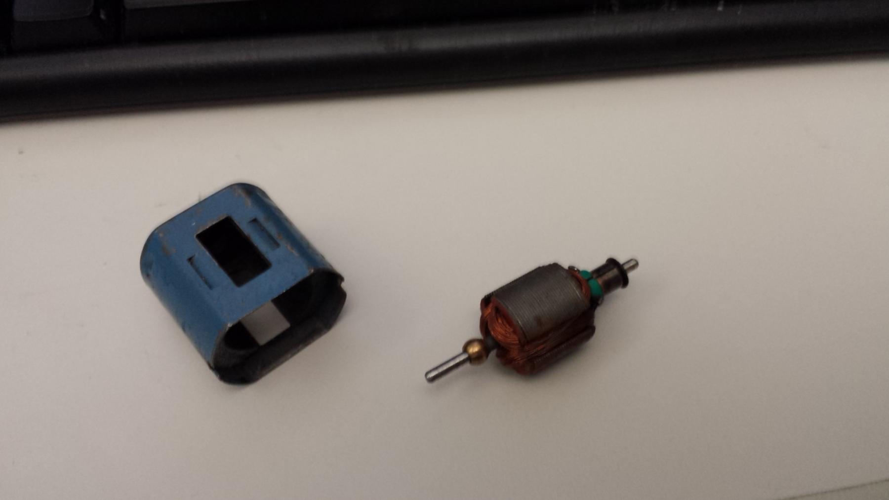
here are my two current candidates, one endbell driver, and one can driver. 


20160112_081250.jpg


the stripped endbell armature had 47 turns on each pole with 27AWG (.014 thick)  wire, and subsequent dis-assembly of the can driver gave 111 turns of 30 AWG (.010 thick) wire. I noticed that the wire was wound counter-clockwise around each pole. the 30 gage windings definitely had some sort if light varnish on them. the 27AWG, not so much, that I could tell. 


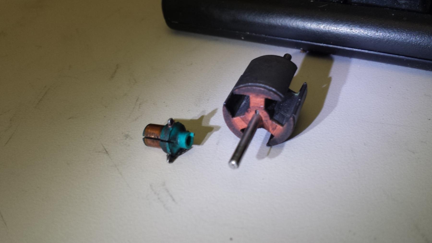
I was surprised to find that the commutators are not adhered to the armature shafts - just a slip fit, though a little snug - but are positioned (as john H had revealed in  the "Clean Parts" thread)  with a tiny tab fitting into a hole on the stack end insulator.  


20160112_091949.jpg


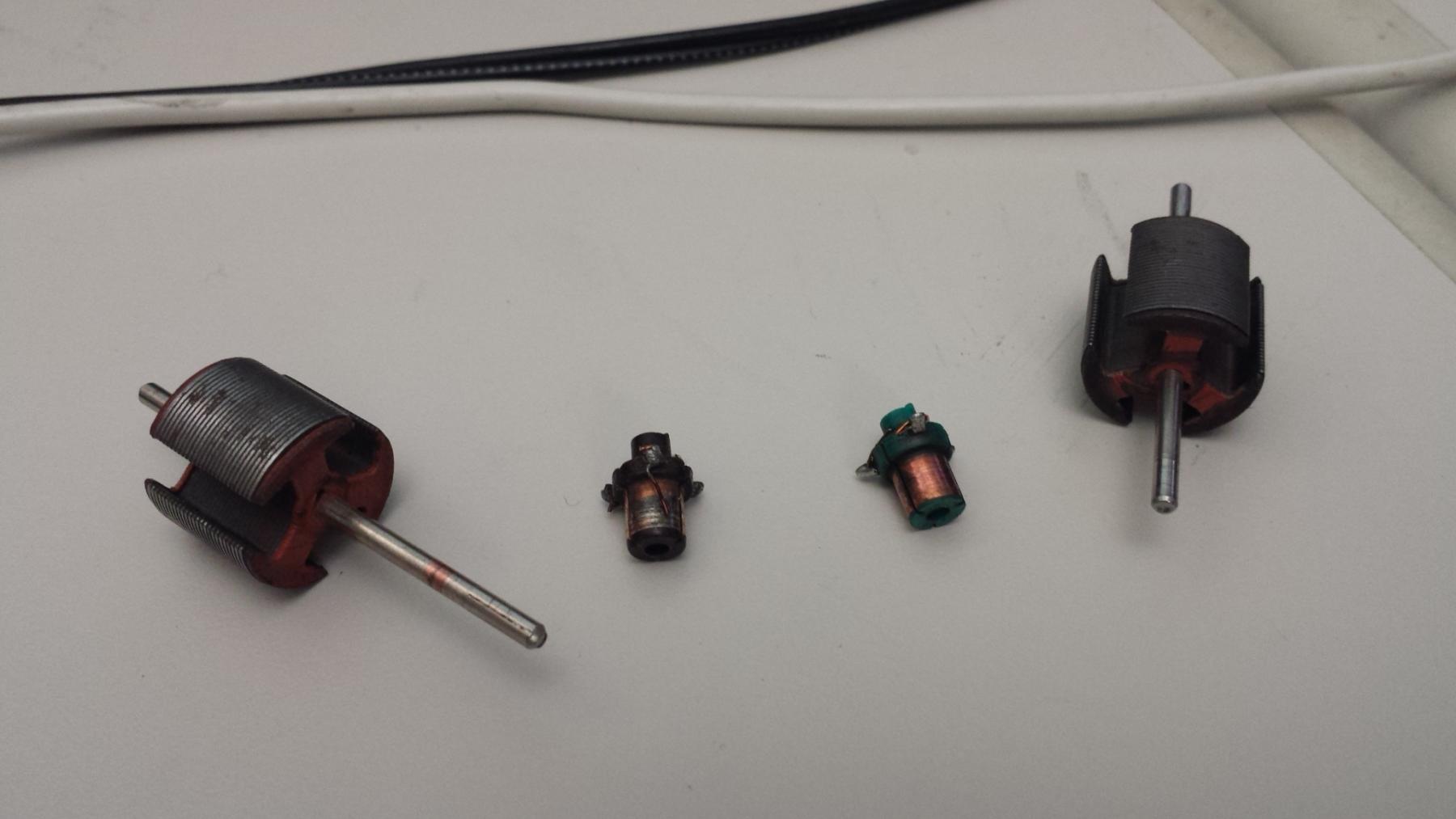
both all apart, endbell drive left, can driver right...


20160112_093817.jpg


the locating tab on the endbell drive armature's commutator ( the black one) does not fit tightly into its corresponding slot, and allows some movement which my calibrated eye tells me is something like +15/-10 degrees, where as the can drive (green) commutator fits tightly into its slot and doesn't really move at all. 


the endbell drive stack measures at .500 where as the can drive stack measures .513.


So...I bought two spools of wire, both 30 and 28 AWG, and at some point over the next couple weeks, I'm going to try winding one of these things up. I'm going to polish and re-use the commutators. somewhere in there I'll also be re-bushing one of my several 36D cans, and then, we'll see what happens. 


so, some questions...


1. in general, all else being equal, is fewer turns of thicker wire a hotter wind than more turns of thinner wire? that seems to be what I've gotten from reading John H's various build threads.


2. does advancing the commutator make the motor spin faster? 


3. does it matter which direction the poles are wound (clockwise versus anti-clockwise) ?


  • havlicek and Samiam like this


#2 Pablo

Pablo

    Builder

  • Administrator
  • PipPipPipPipPipPipPipPip
  • 18,435 posts
  • Joined: 20-February 06
  • Gender:Male
  • Location:Cleveland, Tennessee

Posted 12 January 2016 - 10:20 AM

1. Correct

2. Advancing the comm timing gives you more horsepower (which is a measure of the rate at which work is done, in other words, a measure of acceleration) at the expense of torque (which is a measure of power). More timing=more HP, less torque

3 is for the experts to answer


Paul Wolcott


#3 robbovius

robbovius

    Mid-Pack Racer

  • Full Member
  • PipPipPip
  • 146 posts
  • Joined: 20-March 14
  • Gender:Male
  • Location:MA, USA

Posted 12 January 2016 - 11:48 AM

Thanks Mr Wolcott!


I've just been re-reading a couple threads over in Mr Havliceks forum, and I have this additional question: all else being equal, does fewer turns of the same guage wire yield a hotter motor?


RE :advancing the com - so, if I understand this correctly, advancing the com puts the power higher in the rev range. coming from the IC engine world, HP is a function of Torque x RPM. A high-torque engine that revs at a lower level can be less powerful than an engine that is of lower torque, but revs higher.  does this analogy apply to electric motors as well? I know that electric motors can have 100% torque at 0 RPM 


#4 Pablo

Pablo

    Builder

  • Administrator
  • PipPipPipPipPipPipPipPip
  • 18,435 posts
  • Joined: 20-February 06
  • Gender:Male
  • Location:Cleveland, Tennessee

Posted 12 January 2016 - 12:19 PM

1. Correct, in general. It also results in a lighter weight arm with less rotating mass. It's called "dewinding" and by removing a few turns, securing the remaining winds with epoxy, then re-balancing, and shimming the mags a little closer, you can see some improvement in those old stock motors. The endbell is usually the weakest link.

2. I'll leave that to the experts.


Don't forget in your search for more power, "hotter" arms need stronger magnets. A hot arm with weak magnets is a perfect recipe to cook an endbell.


Paul Wolcott


#5 robbovius

robbovius

    Mid-Pack Racer

  • Full Member
  • PipPipPip
  • 146 posts
  • Joined: 20-March 14
  • Gender:Male
  • Location:MA, USA

Posted 12 January 2016 - 01:58 PM

hmm, thanks for the tip about the magnets. For now, in the interest of simplicity, and observing the  "one change at a time" philosophy, I think I'm going to wind them both with the 30AWG, but one at 100 turns, and one at 80, refurb the bushings in one can and endbell, and then pop them in and out and observe the differences. I have no method of measuring magnet strength, beyond seeing how big a screwdriver I can hang from them. right now, including the motor that got replaced in the Rat Cobra Spl, I have 4 36D can/magnet setups laying about. 


#6 tonyp

tonyp

    Grand Champion Poster

  • Member at Peace
  • PipPipPipPipPipPipPipPip
  • 15,325 posts
  • Joined: 12-February 07
  • Gender:Male
  • Location:Sanford, FL, land of lizards and big roaches

Posted 12 January 2016 - 02:02 PM

Electric motors are considered to have the most torque at "zero" rpm. All the torque is in the initial application of power. From then on its basically all rpm. Torque in electric motors for rc or slots is achieved by using a high rpm motor and gearing it for torque.
  • Pablo and boxerdog like this

Anthony 'Tonyp' Przybylowicz

5/28/50-12/20/21
Requiescat in Pace


#7 Pablo

Pablo

    Builder

  • Administrator
  • PipPipPipPipPipPipPipPip
  • 18,435 posts
  • Joined: 20-February 06
  • Gender:Male
  • Location:Cleveland, Tennessee

Posted 12 January 2016 - 03:09 PM

Interesting, Tony.

When we "blip" for a quick braking effect, would that be considered an "initial application of power" ?

I'm guessing "yes".


Paul Wolcott


#8 robbovius

robbovius

    Mid-Pack Racer

  • Full Member
  • PipPipPip
  • 146 posts
  • Joined: 20-March 14
  • Gender:Male
  • Location:MA, USA

Posted 12 January 2016 - 03:22 PM

Tony, so, as I understand what you've written, for electric motors the torque level is constant across the rev range...


#9 tonyp

tonyp

    Grand Champion Poster

  • Member at Peace
  • PipPipPipPipPipPipPipPip
  • 15,325 posts
  • Joined: 12-February 07
  • Gender:Male
  • Location:Sanford, FL, land of lizards and big roaches

Posted 12 January 2016 - 03:22 PM

Yup. The torque on startup is witnessed by the motor twisting in your hand if you hold it and turn the power on.
  • Pablo and olescratch like this

Anthony 'Tonyp' Przybylowicz

5/28/50-12/20/21
Requiescat in Pace


#10 havlicek

havlicek

    OCD Rewinder

  • Subscriber
  • PipPipPipPipPipPipPipPip
  • 11,198 posts
  • Joined: 20-August 07
  • Gender:Male
  • Location:NY

Posted 12 January 2016 - 04:04 PM

Excellent to see you diving in!


1. in general, all else being equal, is fewer turns of thicker wire a hotter wind than more turns of thinner wire? that seems to be what I've gotten from reading John H's various build threads.


In a word...yes!


2. does advancing the commutator make the motor spin faster? 


Yes, but only in the direction of the advance.  In the opposite direction, the motor will run slower and also get warmer.


3. does it matter which direction the poles are wound (clockwise versus anti-clockwise) ?


Not at all...BUT...depending on how much advance you've dialed-in (or not), it might make doing the com connections a little more fidgety.  You'll see what I mean once you try.  In general. wind in the direction that you're most comfortable, because that will result in neater/tighter/more symmetrical coils.  Have your work area well-lit so you don't get "the squinties", and have your winding crank at a good height...again for comfort.


*When using the Mabuchi (or similar) fiber stack-end insulators, try getting them perfectly centered over the laminations (they should protrude slightly past either side to prevent the wire's insulation coating from getting scratched, cut or abraded).  Once centered, put a teensy dab of CA glue where the edge of the outside of the stack meets the edge of the outside of the insulator on each pole and at each end.  This will help prevent the insulators from moving as you wind.


*It's far more important that you wind as neatly as possible and keep consistent tension on the wire, than hitting any "target" number of turns.  With #30 wire on a 36D, you can do anywhere from 75-85 turns...or more if you like.  There's plenty of room in there, but keep trying to get the same "patterns" as you wind each pole.  It may help to jot down how many turns you got on there for each layer of the first pole.  Then you can try and duplicate those numbers as you do the two remaining poles.


*Before you epoxy the arm, at least check it for shorts.  There should be NO continuity between the shaft and any of the com segments.


*Make sure that the wire is stripped clean where it passes over the com tabs.  A very small amount of insulation on there may result in an arm that either runs well...or doesn't run!  The modern "good stuff" magnet wire (200 degrees C or better) has a tough coating on there that you can NOT simply solder over.


*If you have a way to test resistance, do your com-cleaning before you test.  The grime and carbon on the com can make a BIG difference in your readings.


RE :advancing the com - so, if I understand this correctly, advancing the com puts the power higher in the rev range


No, it will give you more RPMs in the direction of advance (usually CCW when viewed from the end bell.)  Remember, RPMs can translate into "power" by gearing to take advantage of them.  A motor can have more power by a combination of stronger magnets/and or a tighter "airgap" (and a wind to take advantage of them) and a more "efficient motor setup"...less potential power being wasted as heat because of friction.  On the gap between the magnets and the armature:

1)The strength of the field exerted by the permanent magnets on the armature increases exponentially as they get closer.  In English, that means a little shimming may be all it takes.  You can get up to pretty hot winds with the stock Mabuchi magnets by shimming them.


2)You don't necessarily want the magnets just barely clearing the armature, nor do you necessarily want the strongest magnets you can find.  It's not at all difficult today (as opposed to back in the 1960's) to have magnets that are too strong.  A #30 wind may run great with the Mabuchi magnets, and run like a dog with some super strong magnets.


***As you get going, don't screw around with the motor or even the timing too much.  By limiting the variables, you'll be able to better judge how you're doing with the winding.


-john


  • Pablo likes this
John Havlicek

#11 robbovius

robbovius

    Mid-Pack Racer

  • Full Member
  • PipPipPip
  • 146 posts
  • Joined: 20-March 14
  • Gender:Male
  • Location:MA, USA

Posted 12 January 2016 - 11:23 PM

John, thanks for all the advice! At this juncture i do think a KISS ethic is best. I may reduce the number of turns tho. I've got another 36D arm im going to strip tomorrow so i'll have 3 candidates.

#12 Hermit #1

Hermit #1

    Mid-Pack Racer

  • Member at Peace
  • PipPipPip
  • 174 posts
  • Joined: 27-June 14
  • Gender:Male
  • Location:Wichita, KS

Posted 12 January 2016 - 11:48 PM

When you feel a little more comfortable rewinding, and you decide you need better components, I highly recommend you PM Bill Budgenis (member name wbugenis) and pickup some armature blanks and/or commutators.  Good quality stuff at reasonable prices.


  • havlicek likes this
Dave "Hermit" Jones
5/26/??-9/12/17
Requiescat in Pace


#13 boxerdog

boxerdog

    Race Leader

  • Full Member
  • PipPipPipPipPip
  • 877 posts
  • Joined: 10-November 10
  • Gender:Male
  • Location:Modesto, CA

Posted 12 January 2016 - 11:52 PM

Tony, so, as I understand what you've written, for electric motors the torque level is constant across the rev range...

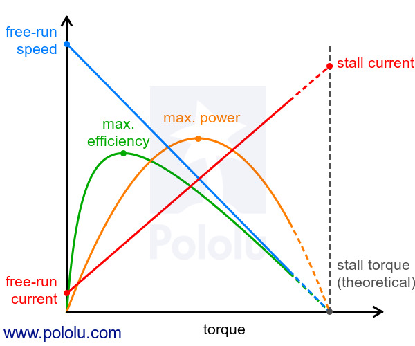
My understanding of this is a little different, so please correct me if needed. The motor makes maximum torque at "stall", or zero RPM. From that point in the RPM scale, the torque decreases more or less in a linear fashion. The "horsepower" or wattage will peak, as a consequence, somewhere between stall and maximum RPM which is determined by many factors. 


In comparison, a gas engine has a torque "curve" and will peak at a given RPM; so the torque and horsepower curves will cross or coincide at 5250 RPM.


JMO.


David Cummerow

#14 Hermit #1

Hermit #1

    Mid-Pack Racer

  • Member at Peace
  • PipPipPip
  • 174 posts
  • Joined: 27-June 14
  • Gender:Male
  • Location:Wichita, KS

Posted 13 January 2016 - 12:10 AM

My own understanding coincides with Boxerdog's.  Couldn't have stated it better ...  :)


Dave "Hermit" Jones
5/26/??-9/12/17
Requiescat in Pace


#15 zipper

zipper

    Checkered Flag in Hand

  • Full Member
  • PipPipPipPipPipPip
  • 1,077 posts
  • Joined: 11-August 10
  • Gender:Male
  • Location:Finland

Posted 13 January 2016 - 05:01 AM

Typically DC Motors behave like this:0J6476.600.jpg?37d25b538bd34ba4233fe286c


  • Marty N likes this
Pekka Sippola

#16 tonyp

tonyp

    Grand Champion Poster

  • Member at Peace
  • PipPipPipPipPipPipPipPip
  • 15,325 posts
  • Joined: 12-February 07
  • Gender:Male
  • Location:Sanford, FL, land of lizards and big roaches

Posted 13 January 2016 - 08:08 AM

Boxer dog, that is pretty much it. Said much better than I did. Lol

Anthony 'Tonyp' Przybylowicz

5/28/50-12/20/21
Requiescat in Pace


#17 robbovius

robbovius

    Mid-Pack Racer

  • Full Member
  • PipPipPip
  • 146 posts
  • Joined: 20-March 14
  • Gender:Male
  • Location:MA, USA

Posted 13 January 2016 - 08:26 AM

Boxer, Hermit, Zipper, thanks! 


in other news, here's the the candidate can and another candidate arm prior to stripping. 


20160113_080312.jpg


the arm measures .67 OD and the ID of the magnets measures .728, giving about a .029 air gap. Is there any rule of thumb regarding number of winds and air gap relationship? 


...or, should I just experiment? ;-) 


#18 havlicek

havlicek

    OCD Rewinder

  • Subscriber
  • PipPipPipPipPipPipPipPip
  • 11,198 posts
  • Joined: 20-August 07
  • Gender:Male
  • Location:NY

Posted 13 January 2016 - 08:27 AM


When you feel a little more comfortable rewinding, and you decide you need better components, I highly recommend you PM Bill Budgenis (member name wbugenis) and pickup some armature blanks and/or commutators.  Good quality stuff at reasonable prices.


...and it goes without saying (although I AM saying :)  ) that Bill is an honorable guy.  You can trust that you will get exactly what you ask for and in a timely fashion!


   So, with all this talk about torque and RPMs, I suppose it's only a matter of time before someone makes a miniature CVT for slot cars  :D


John Havlicek

#19 havlicek

havlicek

    OCD Rewinder

  • Subscriber
  • PipPipPipPipPipPipPipPip
  • 11,198 posts
  • Joined: 20-August 07
  • Gender:Male
  • Location:NY

Posted 13 January 2016 - 08:32 AM

Boxer, Hermit, Zipper, thanks! 


in other news, here's the the candidate can and another candidate arm prior to stripping. 


attachicon.gif20160113_080312.jpg


the arm measures .67 OD and the ID of the magnets measures .728, giving about a .029 air gap. Is there any rule of thumb regarding number of winds and air gap relationship? 


...or, should I just experiment? ;-) 


You can shim the magnets in from .004-.007" per side and get a good bump.  .004" will allow for easy insertion of the shims and magnets while still using the stock "one clip and can tabs" for installing the magnets.  For best results, the shims should be cut from steel and shim stock of varying thicknesses is cheap and easily available.  If you buy .004", you can always use two per side.


***The can has lost it's bushing, so it seems that the arm has a splined shaft.  Not all Mabuchis had this "feature", but you'll have to fix the can bushing and these arms aren't the best for messing around with, since every time you install, uninstall the arm, those splines cut into the steel shaft aren't doing good things to your bushing!


-john


John Havlicek

#20 Pablo

Pablo

    Builder

  • Administrator
  • PipPipPipPipPipPipPipPip
  • 18,435 posts
  • Joined: 20-February 06
  • Gender:Male
  • Location:Cleveland, Tennessee

Posted 13 January 2016 - 09:07 AM

I forgot to say, remove splines before pulling arm out :dash2: Sorry :D  2 options, 1. Try and stick it back in (a real PITA) or 2. Drill out the gimbal and install a bushing or bearing (a goat rodeo). If John knows a better option I'm all ears. Those gimbals are really hard to drill, and as soon as it starts getting hot, it's going to separate from the can. Then you can finish drilling the bushing hole, solder the gimbal back on the can with silver solder, then align and solder the bushing in place with 60/40. Have fun :)


Wheeeeeeeeeeeeeee !!


Paul Wolcott


#21 robbovius

robbovius

    Mid-Pack Racer

  • Full Member
  • PipPipPip
  • 146 posts
  • Joined: 20-March 14
  • Gender:Male
  • Location:MA, USA

Posted 13 January 2016 - 09:33 AM

John, sounds good. Bill in NH clued me in about they "splines" on the pinion ends of some 36D motors. I'm going to cut them down before I try inserting them thru  anything. so far the only 36D I've found the didn't have them was that KB bobcat I put in the Classic Rat Cobra. 


Paul, was kind enough to detail his method of replacing the stock Mabuchi "floating ball" bushings with a fixed oilite - I'd asked him, he hooked me up;-) I'm going to use his method to replace the wiped out ball bushing in the can upthread (as well as the other 36D cans I have)


googling shim stock in 3-2-1...


Oh I almost forgot...how do you identify the + and - leads when you're reassembling a motor?


#22 havlicek

havlicek

    OCD Rewinder

  • Subscriber
  • PipPipPipPipPipPipPipPip
  • 11,198 posts
  • Joined: 20-August 07
  • Gender:Male
  • Location:NY

Posted 13 January 2016 - 09:47 AM


I'm going to cut them down before I try inserting them thru  anything


The issue here is "flattening" the splines without screwing up the shaft.  The safest way I've found is to use a small ("precision" or "jeweler's") file one spline at a time.  It can be a bear and is always tedious.  When I can, I just don't use those armatures and avoid the whole issue.  Generally, the shafts on 36D motors are good, nice and straight and round so, after you get past those splines, you should have a good arm.  The additional problem here is that having either the splines or the flats from removing them can make balancing impossible...unless you use one of the "magnetic" balancers, and those are absolute garbage anyway!

We're getting ahead of ourselves here though, right now it's all about the winding!


-john


John Havlicek

#23 robbovius

robbovius

    Mid-Pack Racer

  • Full Member
  • PipPipPip
  • 146 posts
  • Joined: 20-March 14
  • Gender:Male
  • Location:MA, USA

Posted 13 January 2016 - 11:02 AM

John, that's exactly the method I used to disassemble a couple of those old beat-up EBay motors. in and amongst my various toolsets are small files I use for massaging guitar frets and creating string slots in replacement nuts  and bridges for various guitar repairs. I just used one of those to rub on each "spline" (actually they aren't really splines in the engineering sense, rather they're linear "stakes" made to expand the diameter locally, more like knurls) until they were all low enough to let the shaft pass thru the bushing.


yeah as far as balancing these first experiments, that ain't happening. ;-) my above mentioned simple goal of a running motor is the priority. 


#24 Hermit #1

Hermit #1

    Mid-Pack Racer

  • Member at Peace
  • PipPipPip
  • 174 posts
  • Joined: 27-June 14
  • Gender:Male
  • Location:Wichita, KS

Posted 13 January 2016 - 04:24 PM

Oh I almost forgot...how do you identify the + and - leads when you're reassembling a motor?

Use a cheap magnetic compass to check magnet polarity.  The North end of the compass needle will be attracted to the South pole of each magnet.  One South pole will be the concave face, the other will be the convex face.  With the motor can in an anglewinder/sidewinder position (LH side gear), place the South convex face magnet in the rear of the can, the other magnet in the front.  Positive brush will be in the front of the motor.  It helps to mark the top of the can and endbell so both pieces go together the same way every time - if you reverse the top/bottom of the endbell in the can, your magnet polarity will be backwards. 


Dave "Hermit" Jones
5/26/??-9/12/17
Requiescat in Pace


#25 Pablo

Pablo

    Builder

  • Administrator
  • PipPipPipPipPipPipPipPip
  • 18,435 posts
  • Joined: 20-February 06
  • Gender:Male
  • Location:Cleveland, Tennessee

Posted 13 January 2016 - 05:09 PM

No need to google shim stock; PCH has them (e-slotcar.com)

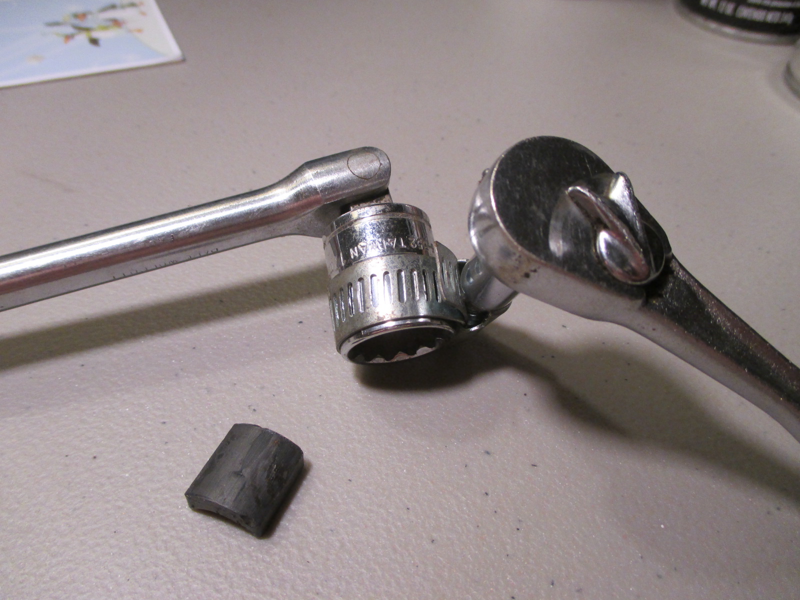
I cut mine with tin snips, then curve them to form fit the mags like this:

IMG_8667.JPG


Paul Wolcott


Electric Dreams Online Shop