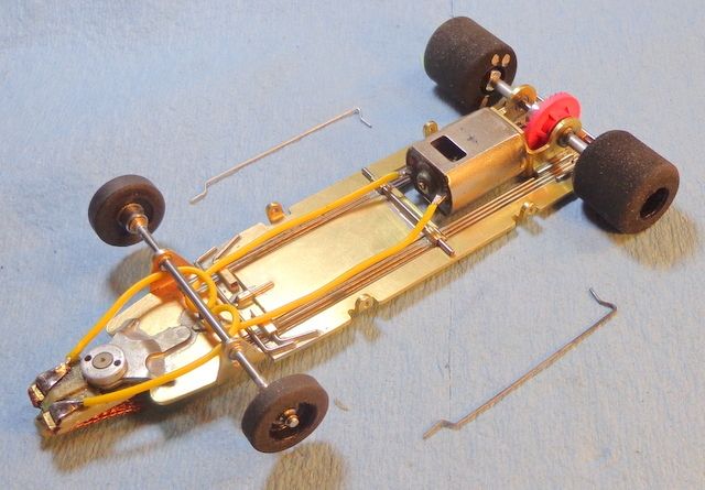
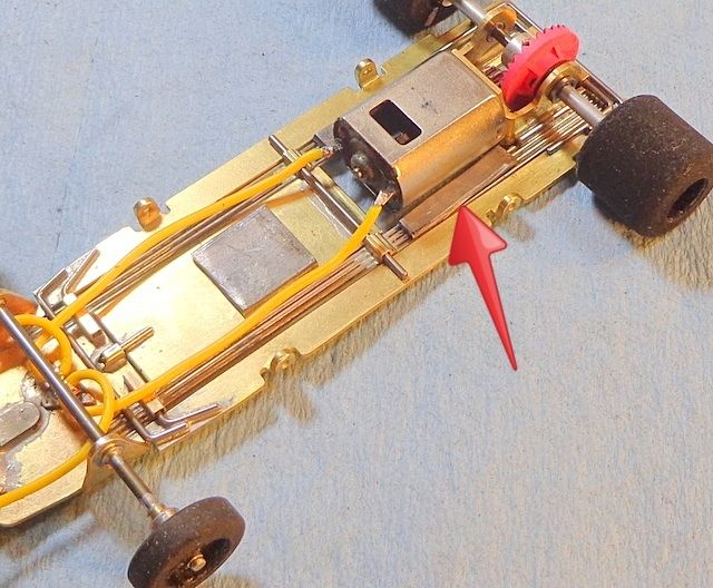
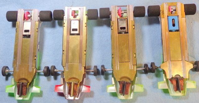
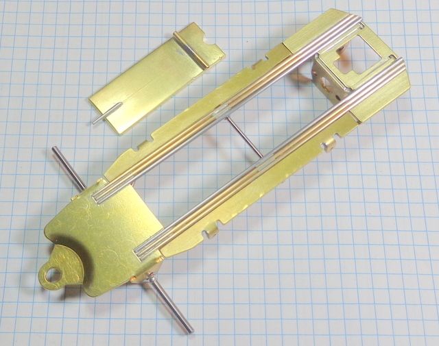
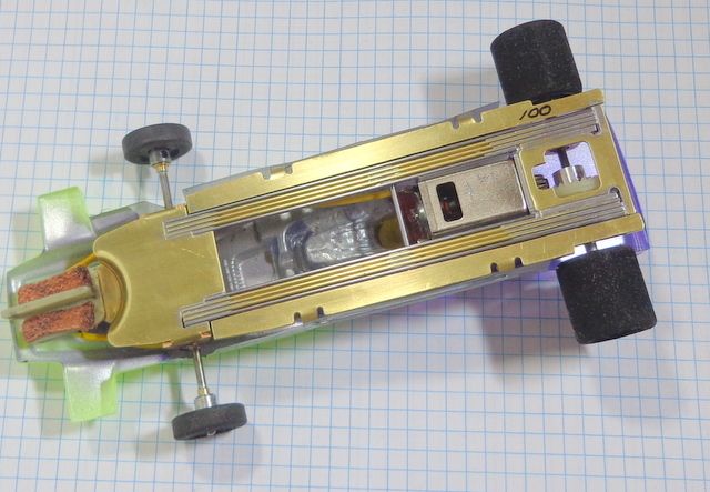
Starting up a new F1 build today with some components from R-Geo. I have been messing with these for a while and have built up several variations. This will be a fairly standard variation but with a rail configuration that I have yet to try with these parts.
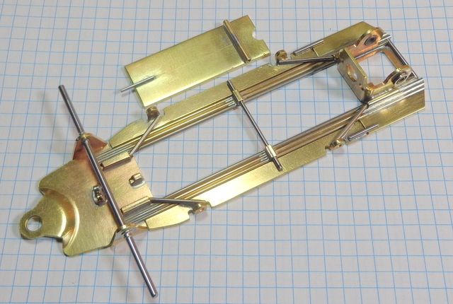
Below is what you’ll get if you order a “Shark” F1 kit from Rick. There are variations but this is what I got. Nosepiece, bracket, and bracket brace are all .050" brass. Pans and center weight are .062" brass. Steel guide reinforcer is (I think) .032".
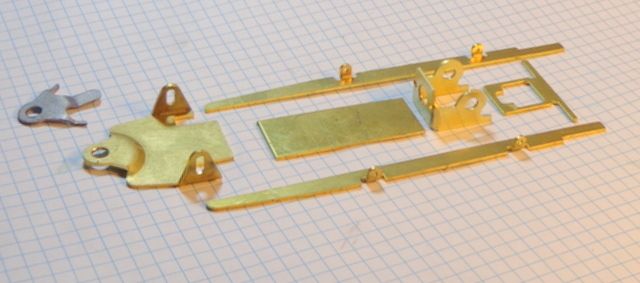
First step is always to detail your bracket. If needed, sand the bracket face flat. Then, check the bracket legs for square to the face. Finally, screw in the motor, slip in your bearings and axle/jig wheels, and check that it all lines up.
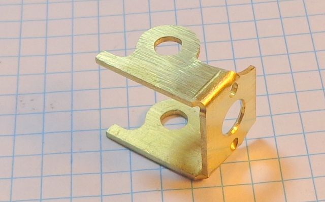
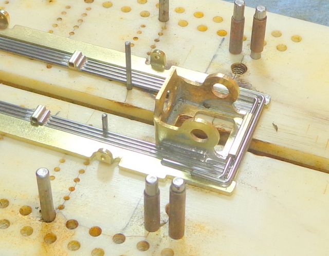
In this view, you can see that this is an angled face bracket. This means that the bracket face is tilted to line up the motor shaft on center to the axle. In the past, I have been using hypoid brackets and I had not paid much attention to this type of bracket. I have to say that now that I’ve used these, I’m sold on the greatly improved gear mesh that these allow.
As an example, in testing something a month or so ago, I took a motor and gear set out of a normal hypoid car and placed them in one of these. The mesh was fine in the hypoid car but the set up gave a little of that mild “clashy” sound that so many Retro cars exhibit unless set up from the start with brand new gears. When I placed that motor/gear set in the angled bracket car, the gears quieted down to a whisper… I was impressed.
You can also see that this bracket has little undercuts right at the junction between the face and the legs. This allows you to tuck a rail or maybe two into this little pocket and get a few more rails in place inboard of the 'normal' ¾” bracket width. I have built a couple of these with seven rails/side of .039". I ran five rails outside and two more inside and was able to get the seven rails in place without going too wide for the pans to fit.
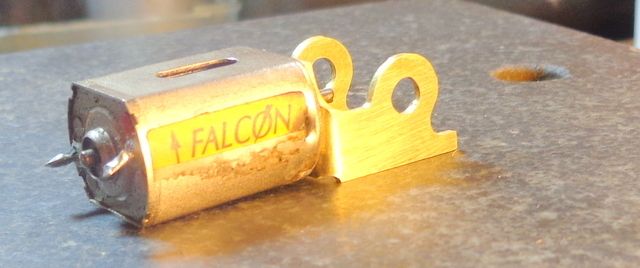
OK... into the Jig we go to line everything up and set our spacing, etc.
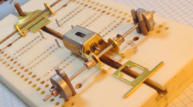
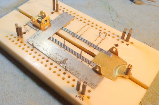
Getting going now. This is going to be four per side of .047" wire. The notches in the nose also accept the classic three x .063" and with a file stroke or two, five x .039". This nose just makes F1 building a breeze with about any rail configuration you want. In this case, I cut my rails, set them up as a pre-fab unit, and tack soldered at both ends. Then I dropped them in place and lightly soldered at the rear of the bracket and the front of the notch in the nose. If this was to be soldered full length, I would flow solder the rail sets and then clean them up before dropping in place.
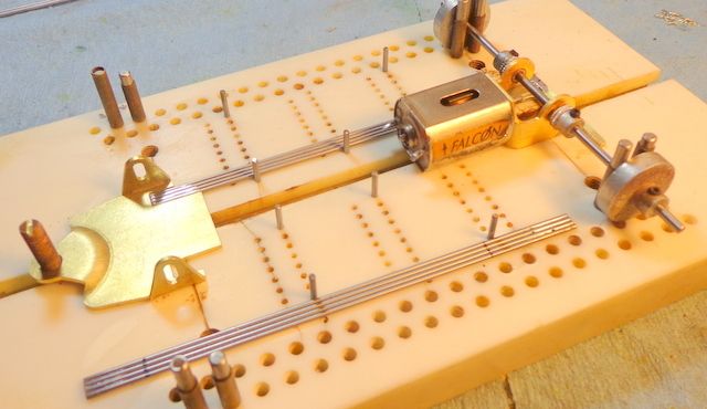
Once the main rail groups are in place, it's a good time to check that your bracket face is square to the chassis. I place the mini square as shown here and check that it's square. No micrometers were injured or endangered during this build but it is a good idea to check square and flat from time to time.
In this case, the main rails will not be full length soldered so take care not to get too much leakage of solder past your connection points. Here’s how I did this.
You can see some ink marks defining where I want the solder to go. These are at the bracket face, the area for the crosspiece tubes, and the also at the nose. I place little bits of notebook paper between the rails, flux up just the area where I want the solder and then solder it quickly with a hot iron. While I’m at it, the crosspiece tube go in place along with a little bit of wire behind to reinforce the joint and these are soldered up as well.
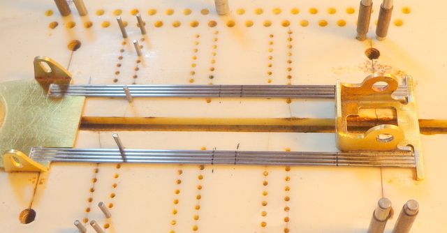
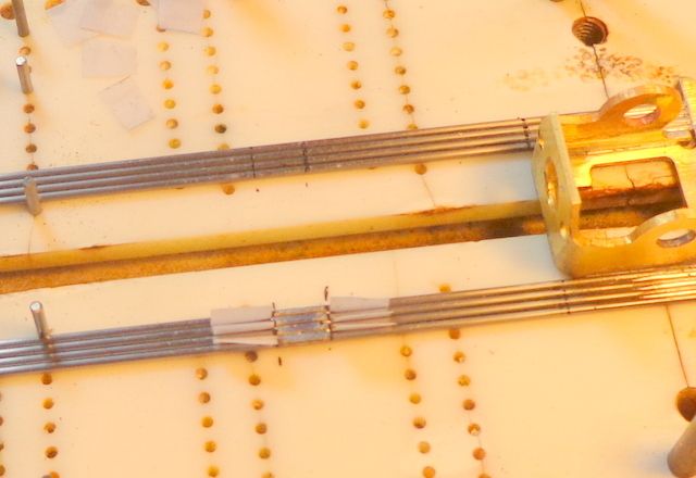
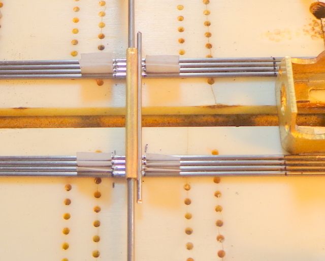
Here, the excess of the crosspiece is trimmed out, the bracket is soldered full to about 1/8” forward of the bracket face, and also a small bit of .055" wire goes in place as a gusset between the bracket leg and the rails. The same is done at the nose, again using the paper to prevent solder from leaking down the rails. At this point, our center section/main rail assembly is completed.
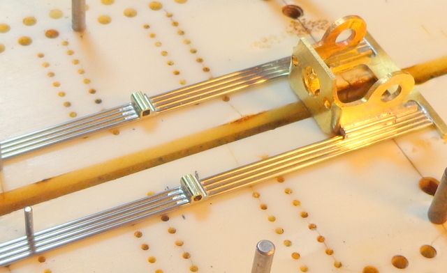
OK… next up is fitting the pans. Here, I have trimmed the front of the near side pan and trimmed the little overhang of the bracket plate. In this case, I’m using the classic full length pan setup, but of course, there are any number of ways to do this. The pan on the far side and the little tail of the bracket plate are shaded for cutting.
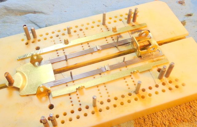
OK… pans are cut to size. Next up are the shaker tubes. In front, I have two bits of 3/32” box tube getting ready to go in place. There’s a piece of 1/16” aluminum tubing holding them in alignment. The shallow U-shaped piece off to the side is a spreader bar that will tie the pans together in front. At the rear, we do the same thing except I used one bit of tubing centered on the bracket plate. Spreader bars at both front and rear are .047" wire but could be about anything.
Important to note that you could eliminate the spreader bar by making the shaker rods one piece and bending to fit in place after inserting through the tubes. That works fine but is a fiddley process and so I use the spreader bars and make the shaker rods two piece for ease in bending.
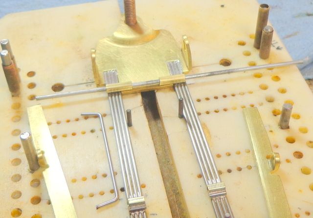
This pic shows the pans in place and soldered together at front via the spreader bar. There is a piece of notebook paper in place between the rails and the pans to provide a small amount of spacing and to keep the solder from going to the wrong places. At the rear, you can see the single shaker tube in place, the spreader bar ready to go in place, and the shaker rods. The far shaker rod is already in place, the near one is set to go in. The shaker rods are .047" wire.
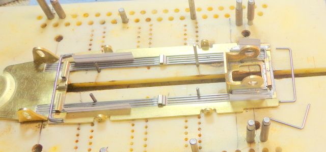
Here is the rear end finished up. Shaker rods in place and soldered and then the rear spreader bar in place and soldered.
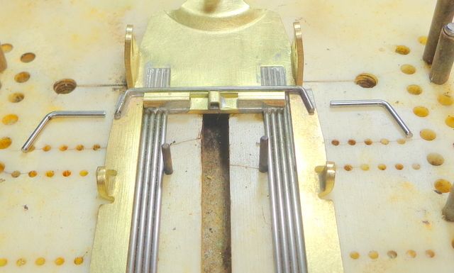
The next two pics show the nose ready to go. First one shows the shaker rods ready to place and the second pic shows them finished up. The tiny little bit of box tube in the center is the front retaining stop for the center weight. Believe it or not, we’re all done but for some little details.
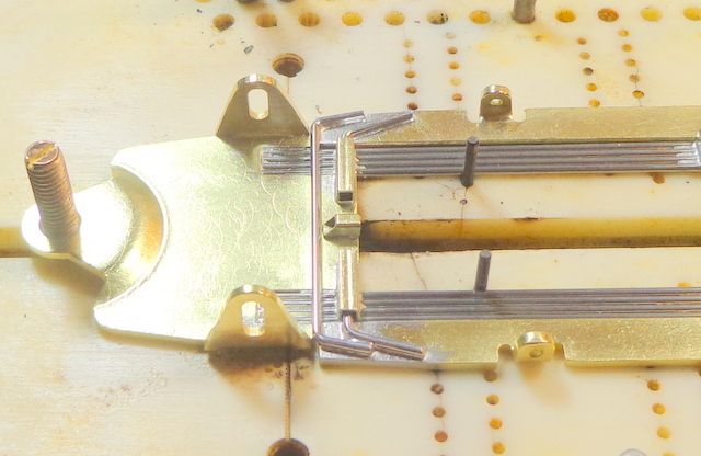
Here it is finished up. The guide tongue reinforcer is soldered in place, front axle is installed, and the center weight is hung. The center weight here is 1/16” brass and goes about 14 grams or so. This will give us a finished weight of about 113 grams all up with body. If you want lighter, you can make the center weight out of thinner brass or leave it out completely. The center weight is soldered to the 1/16” crosspiece which is free in the crosspiece tubes. The front stop is .047" wire.
In general, all movement parameters on this chassis are pretty minimal. I very much prefer body clips on F1 cars whenever practical but of course, pin tubes can easily be added.
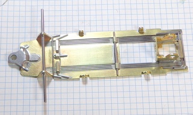
This frame will get tested on a speedway with a Retro Hawk and on a technical flat track with a Mini Brute. The unsoldered main rails will then be flow soldered and the tests repeated.


