Time for a new power supply
#26
Posted 26 February 2017 - 09:24 PM
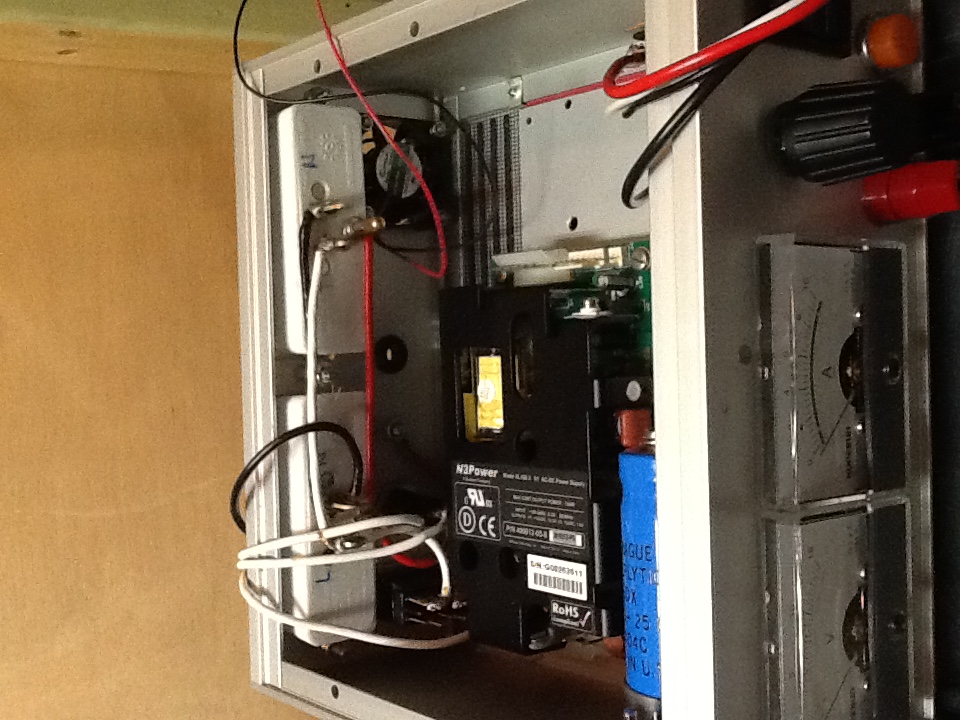
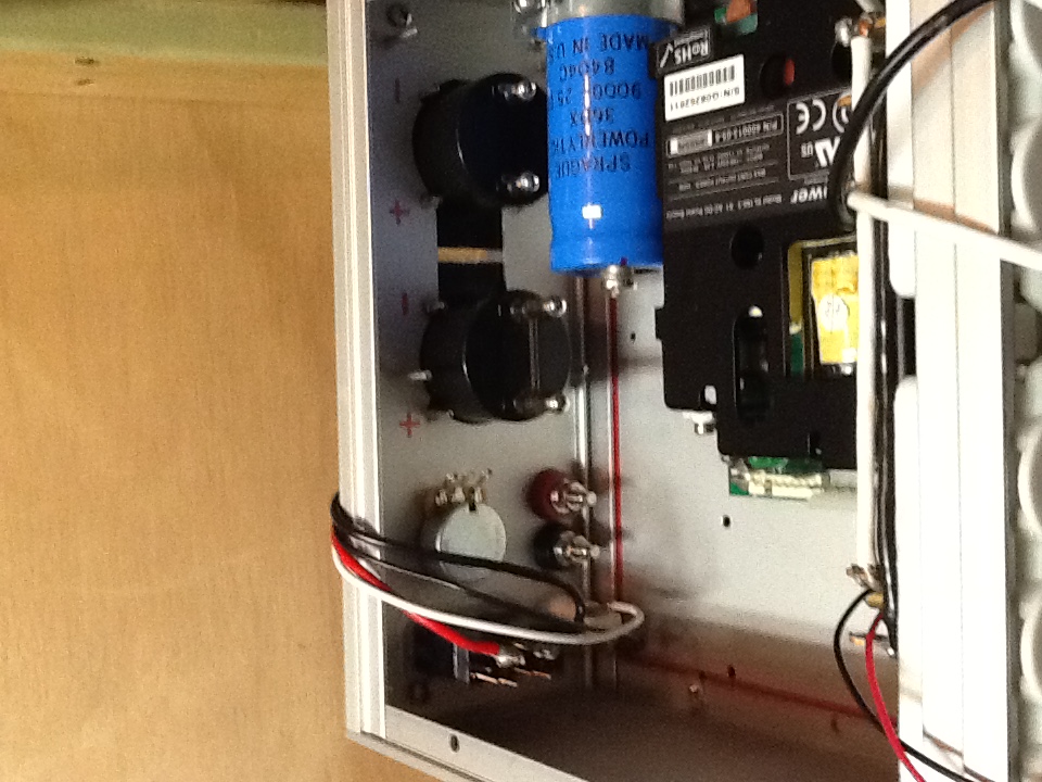
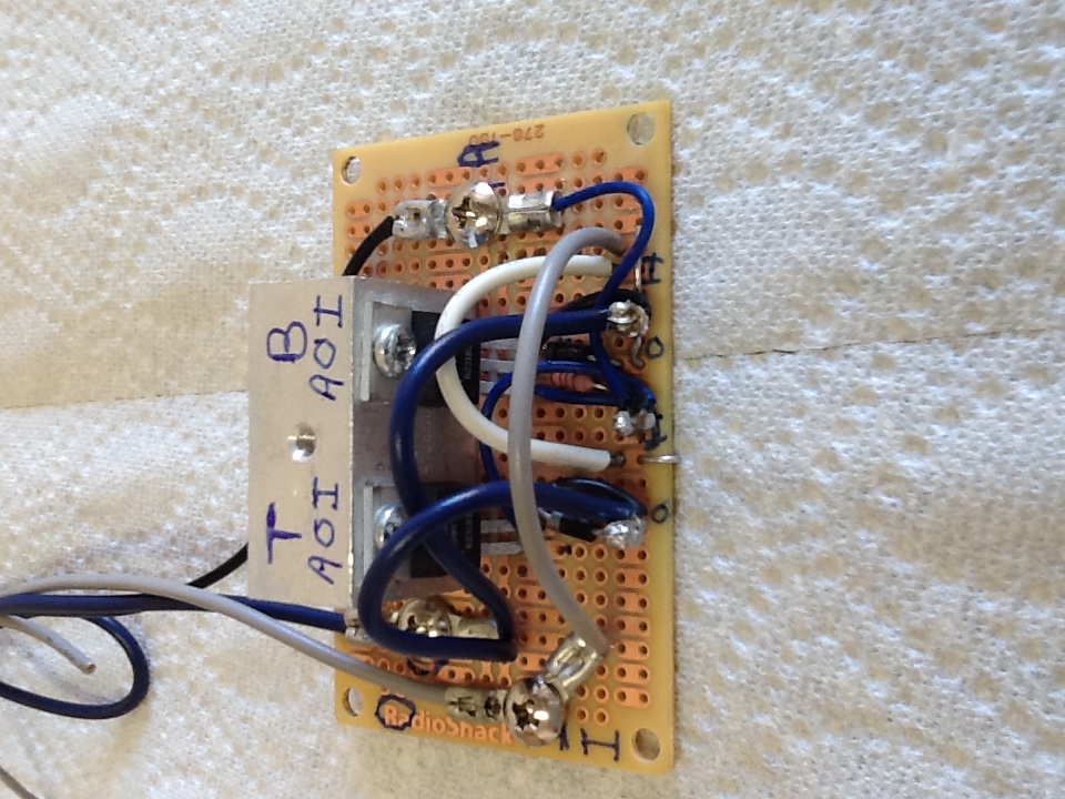
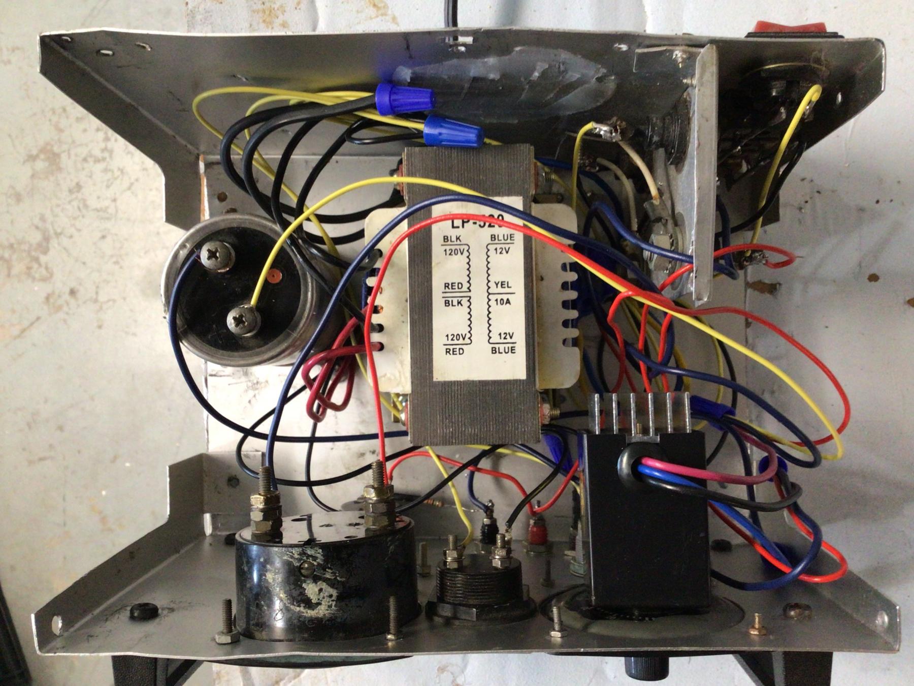
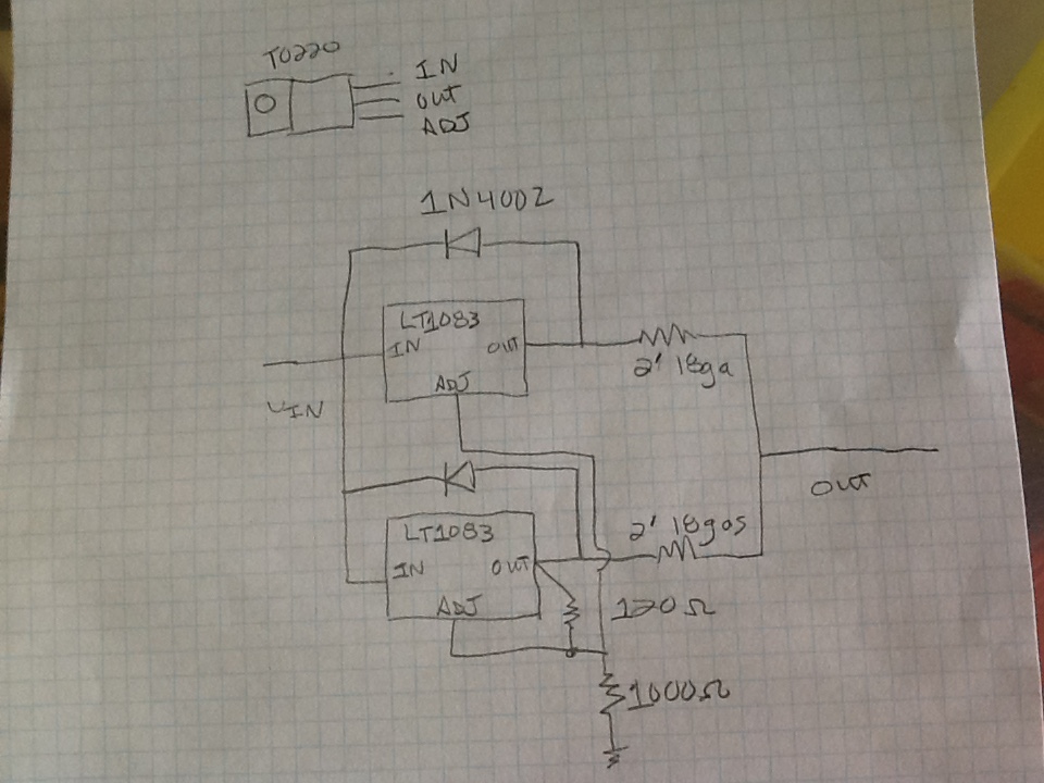
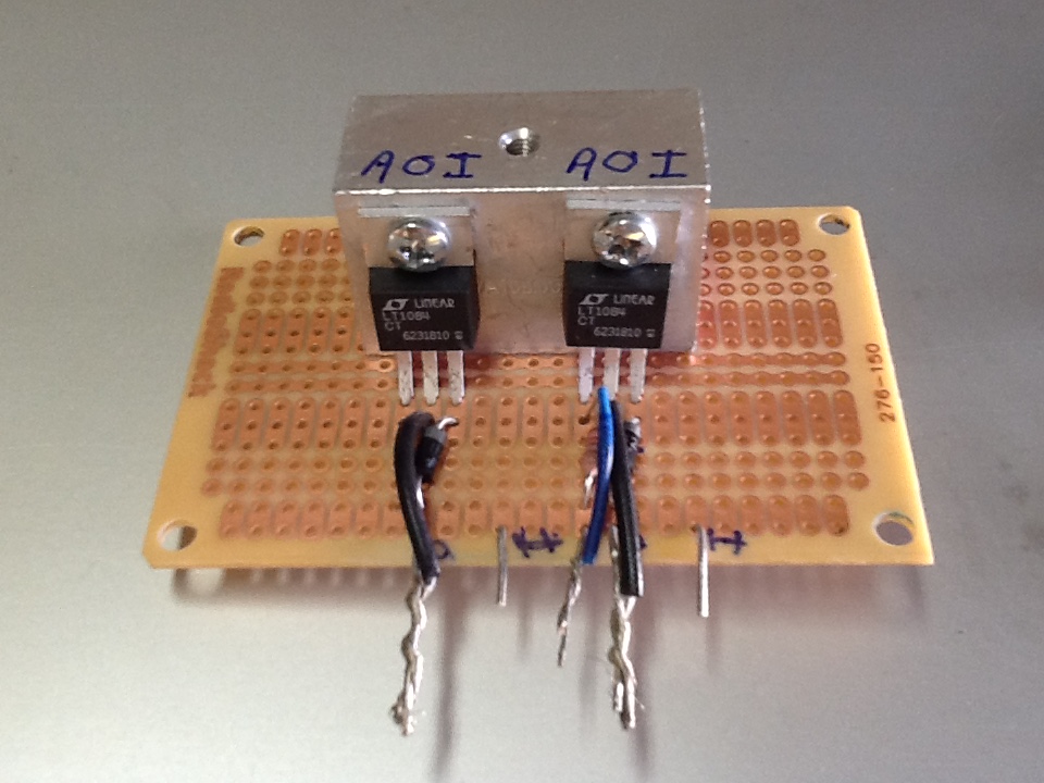
The board is from Radio Shack, the parts are from Digital Key, and the heat sink was salvaged from a scrap box at work. The regulators are only rated for 5A, the application note shows how to gang them to make them 10A capable. The wiring of the control board is point to point with no custom circuit board required.
This assembly is not finished. All the off board connections need work to provide a place for the wiring to attach. Building the board is quite unconventional, but should work just fine.
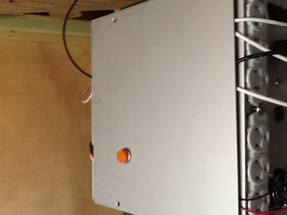
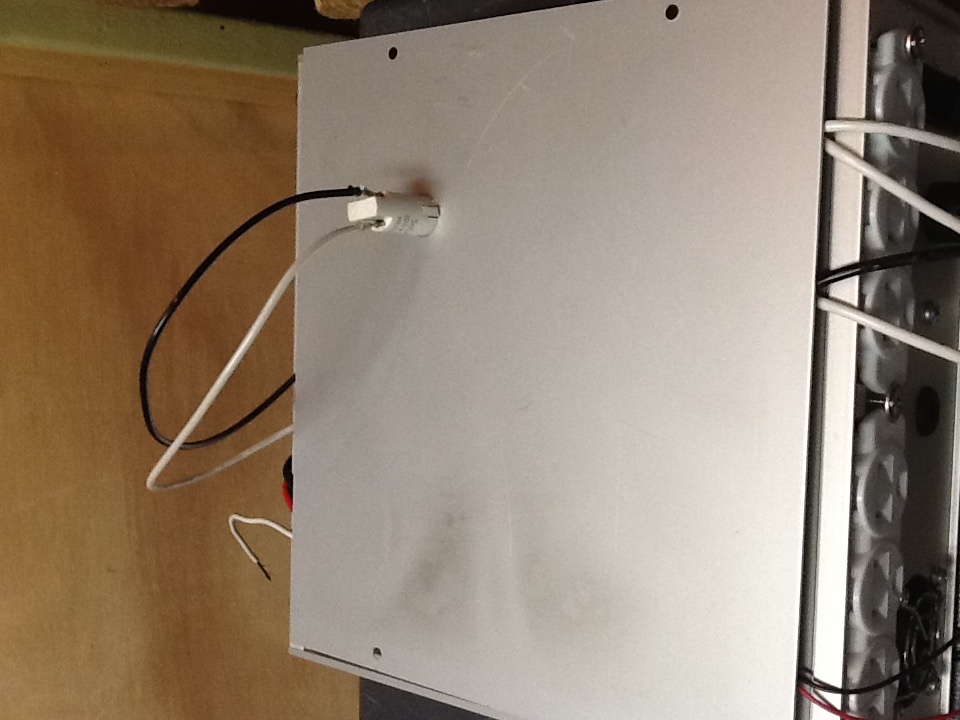
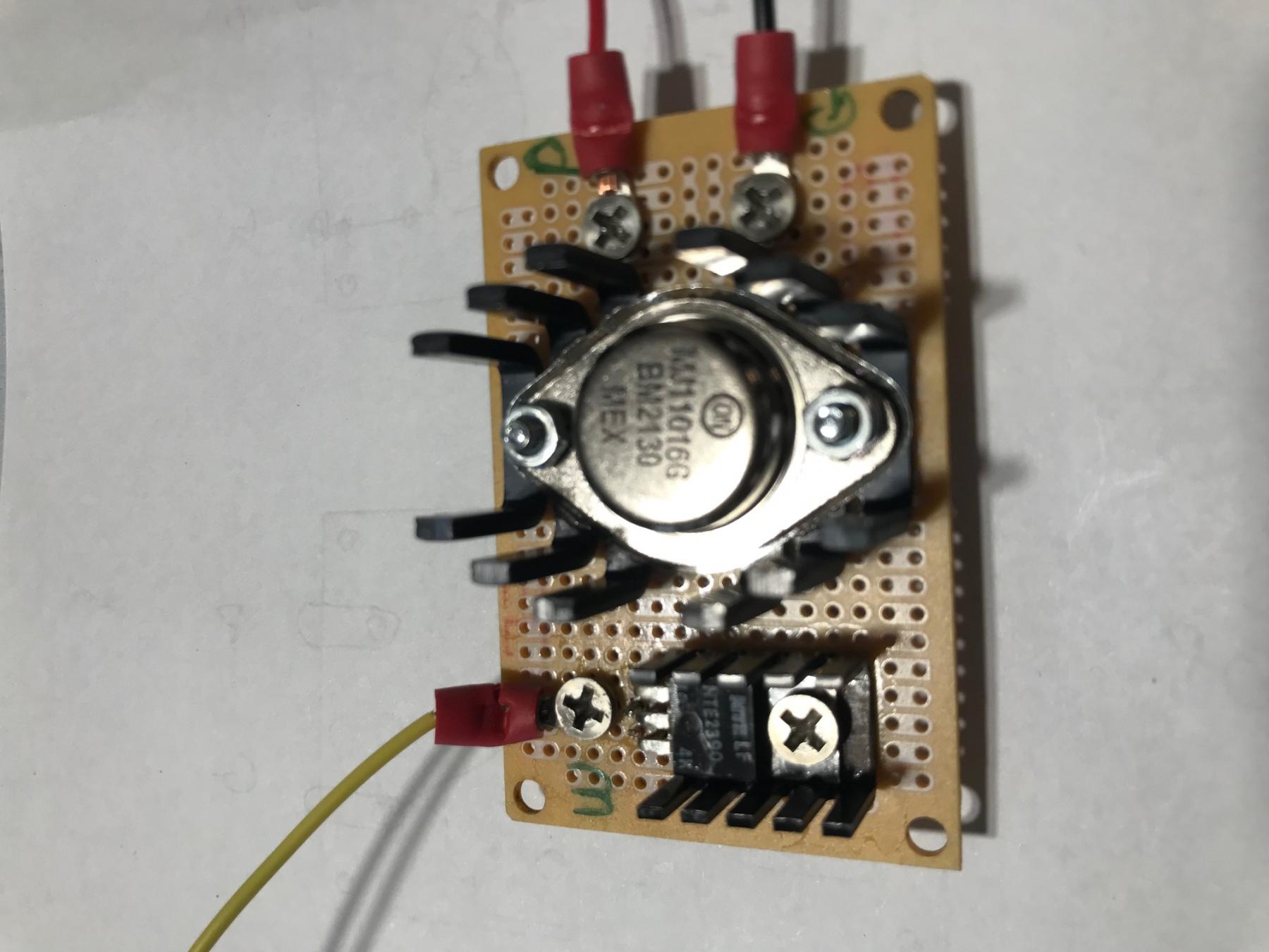
#27
Posted 27 February 2017 - 11:36 PM
L ooks nice and neat.
#28
Posted 27 February 2017 - 11:44 PM
Completely off topic, but do you guys (USA) have on/off switches on your power sockets. Just been watching a couple of TV programs and it looks like they just plugs this in
#29
Posted 28 February 2017 - 06:22 AM
#30
Posted 28 February 2017 - 07:16 AM
Completely off topic, but do you guys (USA) have on/off switches on your power sockets. Just been watching a couple of TV programs and it looks like they just plugs this in
I have a couple duplex outlets (sockets) in my living room that are split, one has constant power, the other is controlled by an on/off switch. The switched outset comes in handy for turning on a lamp in a dark room as you enter the front door. Today, there might be other means for accomplishing the same thing, but my house was built 35 years ago.
I intend to live forever! So far, so good.
#31
Posted 20 March 2017 - 04:25 PM
Very interested in this build! How is it coming along?
Mike
Mike DiVuolo
C.A.R.S. Vintage Slot Car Club
"Prosecutors will be violated"
#32
Posted 20 March 2017 - 06:57 PM
#33
Posted 20 March 2017 - 07:47 PM
Cool, thanks Chris! Getting sidelined these days is easy!
Mike
Mike DiVuolo
C.A.R.S. Vintage Slot Car Club
"Prosecutors will be violated"
#34
Posted 22 March 2017 - 05:30 AM
- mdiv likes this
#35
Posted 22 March 2017 - 05:25 PM
Looking good!
Mike DiVuolo
C.A.R.S. Vintage Slot Car Club
"Prosecutors will be violated"
#36
Posted 08 May 2017 - 08:54 PM
The module that controls the voltage from the regulated supply is wired and completed. I used crimped lug connectors bolted to the board instead of a connector to get the wires off the board. The module is mounted with spacers to the bottom of the chassis.
The AC power indicator for the power plugs on the back is installed on the top cover.
All the other connections are wired and ready to install with wire nuts to make changes and repairs easy. The sharp eyed reader will note that the connectors to the regulated supply for AC in and DC out as well as the 120V AC power cord are not yet installed.
- Benno - SAC likes this
#37
Posted 08 May 2017 - 11:30 PM
#38
Posted 29 January 2022 - 06:21 PM
I have made a couple of updates since this first build and will post them shortly.
- mdiv and Phil Smith like this
#39
Posted 06 November 2022 - 06:19 AM
I didn’t like the way the regulators worked in the 5A range, despite measures they would go into thermal shutdown. So I built an old school control with a MOSFET and NPN transistor. It never did what I wanted exactly, so I have replaced it too.
#40
Posted 06 November 2022 - 06:44 AM
I replace the controller with a PWM from Amazon 12V 10A for less than $10. It came with a knob and has an on/off switch built in. I ran out of time getting the previous one right and just moved to an off the shelf solution.
#41
Posted 06 November 2022 - 06:56 AM
Back to the original 1981 box. I straightened the case, added a new 16V 10A transformer and the same PWM controller. Rewired everything. Cost was about $30. You can see the PWM in the open photo, the black case with the power supply heat sink.
- Rob Voska likes this
#42
Posted 06 November 2022 - 07:02 AM
This is really old school, transformer, diode bridge, big cap, PWM, and gauges. It is not a regulated supply and has all analog displays, but works fine and sits nicely on the bench. I connect everything with wire nuts for easy service. It is a bit heavy compared to modern regulated supplies.
#43
Posted 06 November 2022 - 09:02 AM
Very impressive, you're a NASA grade engineer
#44
Posted 06 November 2022 - 09:39 AM
Hahahahaha! Kind of you, but in the circles I work with, this is, well, not so impressive. Program Management Aerospace is my comfort and strength compared to this fun stuff.
#45
Posted 06 November 2022 - 11:41 AM
I rebuilt a small, 2-amp DIY power supply I purchased from someone at work and turned it into a low voltage supply for testing and breaking in motors. I used the parallel IC regulator approach using two 7-amp regulators similar to the ones used here initially. I think the problem encountered here with the regulators going into thermal shutdown is insufficient heat dissipation. Aside from the block of aluminum, I'm assuming this was attached to the housing. I used much more heatsink area than this and have no problems with thermal shutdown even on motor break-in runs of an hour or more. My supply provides 1.25 to 6.97 volts at 8 amps rms (higher peak), the limits of the transformer I used.
- Greg Erskine likes this
#46
Posted 06 November 2022 - 03:04 PM
Yes, could be, but they were never very warm when they shutdown, so after a bit of tinkering, moved to a different solution.