Building race-winning C-cans
#1
Posted 12 June 2006 - 06:15 PM
* * *
With the permission of the author, George Shannon, I'm going to post this motor-building article from the second issue of the now-defunct "Slot Car Enthusiast" magazine. And since I have the original photos in my files, the pictures will be in color, as opposed to the B&W of the original printed article.
While this article is almost ten years old, it still has a lot of good info, even for racers building motors other than C-cans. Because this is a long article, it will be split up among several posts. George did want me to tell you that he no longer recommends the Slick 7 can bushings and now uses JB Weld for securing magnets.
* * * * * * * * * * * * * * * * * * * * * * * * * * * * * *
Building Race-Winning C-Cans
by George Shannon
In slot car racing, as in full-size racing, horsepower is the name of the game. In classes that don't use spec or sealed motors, careful assembly, which is usually termed blueprinting, is what makes horsepower and wins races. Blueprinting basically means to assemble a motor with the highest possible level of precision, with bearings coaxial, magnets parallel and exactly 180-degrees apart, and clearances at specific figures, all pointing toward the goal of maximum performance.
This article spotlights the C-can slot car motor, which has been commercially available in the slot car market for many years and which is used by both 1/32 and 1/24 scale racers around the world. What follows certainly is not the only way to assemble a C-can motor, as each racer has his own bag of tricks, but the techniques described are one racer's way of achieving the kind of precision that usually produces fast and durable slot car motors. Note that many of these techniques are equally applicable to D-cans as well as to other size motors. And be warned that some of the procedures described may not be legal in every racing series, so read the rulebook or check with the tech director before proceeding.
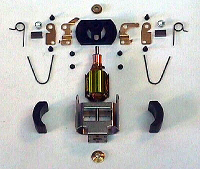
__________
Parts List
Pro Slot thin motor can
Pro Slot endbell & hardware
Mura C-can magnets
Pro Slot S16C armature
Pro Slot Golddust brushes
Champion Light springs
Slick 7 can bushing
FastOnes motor screws
__________
First we must gather the parts and tools required to build a race-winning C-can. The parts list on this page shows the components we will use in the construction of this motor. One may start with a complete motor or one may pick and chose from different manufacturer's parts, as we have done. We will assume that we have obtained matched (equal strength) magnets and a balanced and tagged armature appropriate to the class being raced. We must also assemble a few specialized tools to help us achieve the level of precision we are seeking. Some of these, such as the armature slugs, dial calipers, and brush hood alignment tool, are necessities. Others, such as the endbell alignment jig, the spring tension tool, and the diamond brush radius hone, are optional or can be substituted for.
__________
Tools List
Camen .530 & .525-inch armature slugs
DRS C-can alignment mandrel
Slick 7 brush hood alignment bars
Magnehone brush hood tool
Magnehone brush radius tool
Magnehone armature tool
PureFast endbell alignment jig
Sonic Fiddlestick spring tension tool
Dial calipers
3M Double-Stick cellophane tape
Super glue
Lighter fluid
400-grit Wet-or-Dry sandpaper
__________
The order in which we approach the blueprinting process is important. The following steps must be done in the order indicated to achieve the proper results. Additionally, it is very important to check and recheck all measurements as we proceed. Make certain that everything is accurate before gluing or soldering. Always remember the old adage about measuring twice and cutting once. It is much easier to do it right the first time than to fix it later.
The first order of business, after removing the can bushing if one is installed, is to grind away the spot welds on the inside of the curved surfaces of the can. In many cases, these welds form small bumps which will prevent the magnets from making full contact with the can. A Dremel MotoTool or similar small grinder with the appropriate stone makes short work of this.
Next, we will true the motor can, as this mass-produced item is often out of square or bent. The easiest way to straighten and true the can is to use the appropriate C-can mandrel. If the can won't slide easily onto the mandrel, push it on and then tap softly with a brass hammer on the curved surfaces and at the edges, where the curved surfaces meet the flat sides, until the can will slide easily on and off the mandrel. Be certain that the can fits onto the mandrel in both of the two possible orientations before considering this step complete.
After truing the can, solder the can seams on both curved surfaces for greater strength and stability. To achieve better solder bonds, sand the plating away on either side of the seams and scrape a hobby knife backwards down the seams before soldering. File any excess solder present after soldering, and then recheck that the can slides easily on and off the can mandrel.
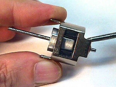
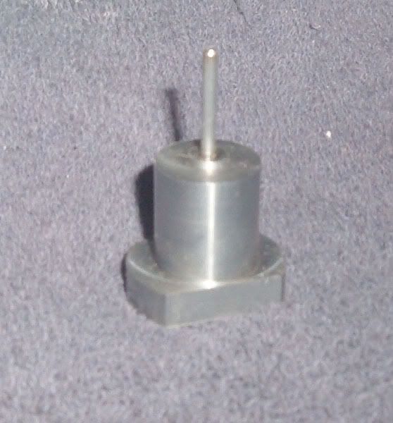
Now we want to establish the bushing axis. Slide the magnets into the can and install the spring clips that retain them. Take an armature slug of a diameter that will fit tightly between the magnets (for our motor, this is a .530-inch slug) and install a can bushing on the short end of the slug's shaft before inserting it into the hole formed by the magnets. If the bushing will not seat into the hole in the end of the can, it will be necessary to ream this to a larger diameter. The can bushing should fit loosely in the hole before soldering. Test fit the endbell to be sure that its bushing is not off-center and that the endbell will fit properly into the end of the can. What we are doing here is using the magnets to locate the armature axis and as we proceed, all other installations will pilot off of this axis.
Next we must install the endbell onto the can and drill the holes for the screws, if they are not already present. (It is a good idea to mark the endbell and can so that the endbell will always be installed in the same orientation; an engraver works well for this.) We want the endbell to fit fully and squarely into the can when the screws are installed. One way to accomplish this is to position the endbell properly and then to lightly glue it in place using cyanoacrylate (super glue) while drilling the holes for the four endbell screws (and always use four endbell screws). The Pro Slot can we are using is a bit different from some of the other C-cans on the market in that the can does not restrain the endbell's rotation. Temporarily install the brush hoods and the brush hood tool onto the endbell and then place the assembly into the endbell alignment jig to square everything up before gluing the endbell in place. Carefully drill the first hole, making certain that the drill is aligned 90-degrees to the can in all four directions. A cordless Dremel MotoTool on slow speed works well for this task. Install a screw in each hole before drilling the next one. Drilling the endbell holes is a critical step as we only have one chance to get it right. If the holes aren't right, i.e. if the endbell doesn't fit flush and square, we will have to buy another endbell and try again. After the four screw holes have been drilled, and before the super glue has a chance to fully harden, break the endbell loose from the can and clean off the small bits of glue with a hobby knife. Reinstall the endbell onto the can with the four screws to be certain that we have achieved the square and snug fit we are striving for.
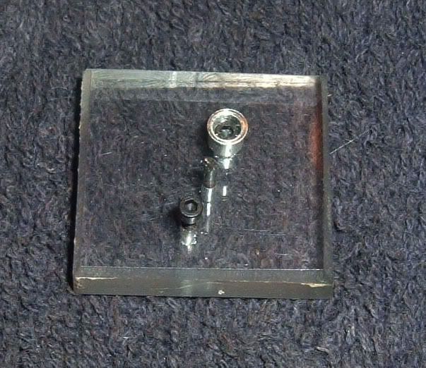
Now solder the can bushing in place after sanding off the plating around the hole. Be certain that the bushing is fully seated and that there is solder completely around the circumference of the bushing. Do this with the endbell, slug, and magnets in place with all four screws inserted. Stand the motor can in a block of wood which has a hole for the slug's shaft. Rotate the motor under the soldering iron to achieve the 360-degree solder fillet desired, using only enough solder to get a good bond. If the endbell bushing is not secured in the endbell, now is the time to remove the endbell and to carefully glue the bushing in place using a small drop or two of super glue. Use an old armature to seat it in the endbell's bushing recess. Again, this should be done with the endbell on and all four screws installed in the can.
When everything is cool, remove the endbell and the slug, install the armature, and reinstall the endbell to check the bearing alignment. The arm should spin very freely in its bushings. If it doesn't, correct the problem now before proceeding to the next step, resoldering or regluing as necessary to achieve a free-spinning armature.
Next, we must determine the magnet position which will locate the armature in the can such that the brushes properly contact the commutator and such that the armature floats between the bushings. We don't want either end of the arm to contact the bushings yet the commutator must be positioned to allow full brush contact. Accomplish this by using dial calipers to push the magnets toward the endbell end until the armature floats in the magnetic field in the correct position. Once this magnet position is achieved, write down the distance between the end of the can and the end of the magnets as shown on the dial calipers. This measurement will be needed when gluing the magnets.
(con't in next post)
#2
Posted 12 June 2006 - 06:16 PM
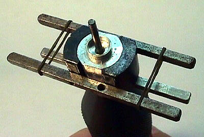
Before installing the magnets, first align them outside of the can using the following technique. Take an armature slug .005-inch smaller in diameter than the slug which fits tightly into the magnets (in our case this is a .525-inch diameter slug) and wrap it with exactly one turn of double stick tape (3M brand works well and is very close to .0025-inch thick). Lay the tape down evenly with no bubbles and be certain not to let the tape project over the ends of the slug itself. It helps to use a pin vise to hold the slug while doing this. Slide a brush hood alignment tool onto one end of the slug's shaft, pushing it flush with the bottom of the slug and holding it there with the pin vise. Keeping the ends of the tape from between the magnets, gently stick the magnets to the double-stick tape and square them to the hood tool along the bottom. Take two more hood tools (or any strips of stiff metal) and use these to square the sides of the magnets. Small rubber bands, such as those used for braces, are helpful here; you can also use the small o-rings found on 1/2 or 5/8 inch front wheels. When the magnets are fully aligned (sight carefully along the alignment bars to be certain they are), squeeze hard with a couple of fingertips to stick the magnets firmly to the tape-wrapped slug. Done properly, this results in almost perfect magnet alignment, assuming that your magnets are the same size.
To install the magnets in the can, remove the alignment bars, being certain not to disturb the magnets themselves. Carefully slide the magnet and slug assembly into the can and install the endbell and screws. Using the dial calipers locked on the measurement previously determined, push the magnets gently toward the endbell until they are in the desired position. Secure the magnets in place using super glue. Allow the super glue to flow by capillary action between the magnets and the can only. Be careful not to glue the magnets to the slug or the endbell to the can! We want to fill the minute spaces between the magnets and the can completely with super glue, effectively "potting" the magnets in place. Set the can assembly aside to cure.
When the super glue has hardened, it is time to remove the slug. Dowse the slug and magnets with lighter fluid (naphtha, like used in a Zippo lighter) and wait a few moments. The lighter fluid will soften the tape adhesive and will allow us to push the slug out from between the magnets with the slug's shaft or with the tip of a screwdriver. If the slug doesn't want to move, apply more lighter fluid and wait a few more moments. The slug may not move much at first but each additional push will move it more and more until it pops right out. Using a Q-tip and lighter fluid, clean any adhesive residue left on the magnet faces. To finish, install the magnet clips, as most rules require them. Install the arm in the can assembly and check that it floats in the magnetic field between the bushings when spun and that the brushes will fully contact the commutator. If the above procedure has been performed accurately, the arm will be exactly centered in the hole between the magnets.
Next, insert the Magnehone brush radius tool into the can and install the endbell and screws. The brush tool, which will be used later to radius the brushes, also has diamond abrasive on the flat faces on either end and we will use these parts of the tool to face both the can and endbell bushings. This will give the armature spacers perfectly flat and square surfaces to rotate against. Using a pin vise, rotate the tool first against one bushing and then against the other until the abrasive has cut a circular pattern into each bushing.
(con't in next post)
#3
Posted 12 June 2006 - 06:18 PM
Now it is time to assemble the brush hood hardware. The fit of the brushes in the brush hoods is very important, as contact between the brushes and the hoods is the main current path in motors that do not use brush shunt wires. Many of the hoods on the market are too tall and using a brush hood alignment bar and a sheet of 400 or so grit sandpaper we will shorten these for a better fit. Place the sandpaper on a flat surface and lay the alignment bar on top of it. Holding the alignment bar, slide the brush hood back and forth along it, allowing the sandpaper to thin the bottom of the horizontal ears of the hood until no more material is removed by the sandpaper. Do this for both hoods.
Use hemostats or locking tweezers to hold the hood in the proper position on its lower plate (line up the holes) and solder the two hood parts together for durability and permanent alignment. Note that this practice may not be legal under some rules. Use the minimum amount of solder, as any excess which gets into the brush slot may prevent the brush hood alignment bar from passing through the hood and will have to be removed using a hobby knife and the Magnehone brush hood tool. If you used too much solder, it can be very difficult to get the hone to pass through the hoods.
Assemble the brush hoods and spring posts onto the endbell plastic after using a hobby knife to remove the locating nubs (see the right side of the endbell in the picture), as these are rarely in the correct position and will hamper efforts to align the endbell hardware accurately.
The PureFast endbell alignment jig makes easy work of endbell alignment, but it is possible to use dial calipers to accomplish the same thing by checking the height of the alignment bar on both sides with the motor can set on a flat surface. When everything is correctly positioned, tighten the four screws that retain the endbell hardware and then recheck the alignment with the arm slug and the hood tool installed into the assembled can and endbell. If it is correct, the brush hood alignment bar will slide easily through the hoods and the armature slug's shaft will pass through the alignment bar's locating hole. When the alignment is right, carefully glue the hoods onto the endbell plastic using super glue. Apply this sparingly to the bottom and edges of the hoods, being extremely careful to keep the glue from getting into the brush holes. Again, this practice may not be legal in every racing series, but it does add durability and ensures that the endbell hardware stays in alignment.
Finally, use the Magnehone brush hood tool to hone the hoods.
Now it is time to prepare the motor brushes. Using an engraver or the tip of a hobby knife, mark the top of each hood and each brush to ensure that the brushes can always be reinstalled in the same hoods in the same orientation. Simple dots or slash marks work just fine. Install the Magnehone brush radius tool into the can and install the endbell and screws. The brush radius tool has two diameters; measure the arm's commutator with dial calipers and use the part of the diamond tool which is closest to the diameter of the commutator. Using a pin vise or a pair of hemostats to keep the cutting surface of the tool in the correct position (the magnetic field will want to pull the tool out of position), install the brushes in their hoods along with the springs. Note that the each spring is "handed" and will only fit correctly on one side. Gently turn the brush radius tool to face the brushes. Work slowly here as the diamond abrasive will quickly cut the brush material. Remove a brush to check the cut after a couple of turns of the Magnehone tool and stop when the curved surface of the brush has been fully cut (see the left brush in picture; uncut brush is on right). Radiusing excessively here simply wastes brush length and shortens service life. If you have been precise during your endbell assembly, the brushes will now have perfectly centered arcs cut into their ends.
(con't in next post)
- Regis4446 likes this
#4
Posted 12 June 2006 - 06:19 PM
Only a few tasks remain before beginning to assemble the motor. Using the Magnehone armature tool, face both the commutator end and the spacer end of the armature. Again, this reduces vibration by giving the arm spacers true surfaces to contact. Using the back edge of a sharp hobby knife, clean out the commutator slots to remove any copper debris that may remain from the cutting of the comm during manufacture.
To begin motor assembly, install the armature into the can using a combination of spacers that allow the arm to remain centered in the magnetic field. If there is sufficient room, install a phenolic spacer next to the comm to act as an oil shield. Always use high-quality arm spacers; these can be either bronze or stainless steel and are available in different thicknesses. This is a trial and error process. The job is done when, after spinning, the armature stops with a very small bit of clearance at each end. Try for a total endplay of .003-.005-inch in a plain bushing motor. When the endplay is in the desired range, install the endbell onto the can with its four screws.
Before installing the brushes, polish all four sides on the back of a business card or on a piece of white paper. Motor brushes should fall into the hoods under their own weight; any sticking or binding here will definitely affect performance. Install the brush springs in the correct orientation, making certain that the short leg of each spring lays flat against the brush. If it does not, carefully bend the short leg using a pair of needle-nose pliers until it does. Finally, using a Sonic Fiddlestick or similar spring tension tool, check that the brush spring tension is the same on each spring. If it is not, replace one spring with others until equal tension is obtained.
With this, the assembly of the motor is complete! Be certain to oil the bushings, using synthetic oil if the Slick 7 can bushing is installed. Use only a tiny amount of oil on the endbell bushing to be certain that oil does not get on the commutator. Break-in the motor under no load on low voltage (3-5 volts) for 20-30 minutes. Monitor the motor temperature during break-in; if it gets uncomfortably warm, turn off the power and let it cool before continuing. Break-in is complete when the brush faces have worn to fully conform to the commutator surface.
Is it necessary to perform this amount of work to build winning slot car motors? Probably not, but more than likely the racers who win week after week assemble their motors in a similar manner or pay someone else to do so. And we certainly wouldn't blame anyone if they would rather buy a blueprinted motor off the wall rather than perform these tedious and time-consuming steps for themselves. But if they like to win...
(end of article)
- Chris Stemman likes this
#5
Posted 12 June 2006 - 06:47 PM
Beautiful work. And this shows EXACTLY why when I will need one of those, I know I can count on you...
Philippe de Lespinay
#6 Bill from NH
Posted 12 June 2006 - 08:20 PM
Can you shed some light on the author George Shannon's background? I don't believe I've ever heard who he was.
#7
Posted 13 June 2006 - 10:36 AM
- team burrito and Geary Carrier like this
Gregory Wells
Never forget that first place goes to the racer with the MOST laps, not the racer with the FASTEST lap
#8 Bill from NH
Posted 13 June 2006 - 08:07 PM
#9
Posted 16 December 2006 - 12:09 AM
Mike Boemker
#10
Posted 17 March 2007 - 05:55 PM
Great article. Just a newbie on this forum today. A lot of info I did not know! Will definitely come in handy.
#11 Bill from NH
Posted 17 March 2007 - 09:03 PM
Nice to have you on Slotblog! Most of the steps shown in this article also apply to building D-can motors if you happen to race any of them.
#12
Posted 18 March 2007 - 09:20 AM
Paul Wolcott
#13
Posted 22 April 2008 - 09:32 AM
Tim
- Cheater likes this
#14
Posted 22 July 2008 - 08:38 PM
- Cheater likes this
Ed Burke
Team Jerk! Slot Car Racing
Race Place
#15
Posted 26 July 2008 - 05:24 PM
Ed Burke
Team Jerk! Slot Car Racing
Race Place
#16
Posted 26 July 2008 - 09:56 PM
I have a Thorp brass one that's 35 year old and a newer Sonic SS one that's about 8-10 years old.
My experience has been they do work, if you use them correctly. First, make sure you're placing it at the same position on both brush springs, and second, be sure the spring arms aren't binding on the brush hood hardware. It works well for setting one side's spring tension relative to the other side. Keep in mind that the springs used inside the Fiddlesticks vary slightly with some being stronger than others. Therefore, it's possible to obtain different readings when you use different units. <G> If you want to be anal, you can calibrate the marks on any unit with a gram scale. Push down on the gram scale with the fiddlestick until it's at the first mark, then record the scale's reading. Push down to the second mark, then record its reading, and likewise, do readings for the rest of the marks.
- gotboostedvr6 likes this
I intend to live forever! So far, so good.
#17
Posted 27 July 2008 - 01:02 PM
And this handy dandy tool makes blueprinting as the above article states as old school. We have all read the article and the many steps. This original design has been copied by other manufacturers. It makes setting magnets so easy, you will wonder why it has not been done this way for 40 years. Set the magnets on the tool, set tip to tip with your calipers and slide in set-up untill flush with can. Slide in can , drop of glue to hold, remove the tool, and flood with glue to secure. Perfect can! Magnet depth set, airgap set, and you didn't have to beat up the can because it is built center out. Fine tune with an aluminum slug with endbell installed and perfect blueprinted set-up in five minutes.
The rest of the article about hardware, etc., is spot on.
Rick Bennardo
"Professional Tinkerer"
scrgeo@comcast.net
R-Geo Products
LIKE my Facebook page for updates, new releases, and sales: Rgeo Slots...
Lead! The easy equalizer...
#18
Posted 03 March 2011 - 04:41 PM
Chris
- Cheater likes this
#19
Posted 31 July 2012 - 06:44 PM
It would be nice to find though some nice places to actually buy these tools though.
- Cheater likes this
#20
Posted 31 July 2012 - 06:59 PM
Most of those tools are either still available or can be substituted for. Please keep in mind that this article was first published thirteen years ago, in 1999.
And though many will challenge or carp about this claim, I feel the trend is now NOT to work on motors, but to use sealed units. For me, that's a positive trend.
Gregory Wells
Never forget that first place goes to the racer with the MOST laps, not the racer with the FASTEST lap
#21
Posted 31 July 2012 - 11:19 PM
- Cheater likes this
First Place Loser in the JK Products
International D3 Builders Competition
#22
Posted 01 August 2012 - 01:03 AM
#23
Posted 01 August 2012 - 01:38 AM
Most of those tools are either still available or can be substituted for.
I think it's still relevant, but where would I find these tools? I know I won't see them at Lowes, I know someone still has to make them for the shops/tracks.
#24
Posted 01 August 2012 - 08:25 AM
Dallas Slot Cars
#25
Posted 01 August 2012 - 08:42 AM
But please, please, please give your local raceway the chance at your business first!
Excellent article. Only thing is don't use Super Glue to hold the magnets in. Use magnet epoxy.
David, a revised magnet-securing recommendation is actually noted in the preamble in post #1:
George did want me to tell you that he... now uses JB Weld for securing magnets.
Magnet epoxy, like Skinner's epoxy, is certainly the best product for securing magnets, but I think JB Weld works well for C-cans and it's a lot less trouble to use than the super epoxies the Wing racers use for strap cans, as it doesn't require baking to cure.
Gregory Wells
Never forget that first place goes to the racer with the MOST laps, not the racer with the FASTEST lap