Jump to content


Photo

Grinding arm shafts to 1.5mm


  • Please log in to reply
31 replies to this topic

#1 swodem

swodem

    Checkered Flag in Hand

  • Subscriber
  • PipPipPipPipPipPip
  • 1,176 posts
  • Joined: 29-October 14
  • Gender:Male
  • Location:Auckland, NZ

Posted 09 April 2019 - 02:12 PM

Hi,


I have a couple of new ES24 arms (thanks, John Havlicek) that I now need to bring down to 1.5mm for pinions.


1. What's the absolute best way to do this?

2. What's the way you do it?


I'm not sure I want to do it using the arms own power in the can for fear of steel dust getting all inside the can, magnets, BB, etc., etc.


Obviously needs to be very concentric with no run-out (eh, Dave Parotta!!).


Thanks.


Steve Meadows


#2 Jaeger Team

Jaeger Team

    On The Lead Lap

  • Full Member
  • PipPipPipPip
  • 444 posts
  • Joined: 27-January 17
  • Gender:Male
  • Location:Palermo, Italy

Posted 09 April 2019 - 02:49 PM

I'm afraid that an average racer, with common equipment, will not be able to carry out such precise work.
 
It is better to start from an arm with the shaft already milled.
 
My two cents.


Maurizio Salerno

#3 MSwiss

MSwiss

    Grand Champion Poster

  • IRRA National Director
  • PipPipPipPipPipPipPipPip
  • 25,623 posts
  • Joined: 16-April 06
  • Gender:Male

Posted 09 April 2019 - 03:06 PM

Check with the various reconditioners.


They may be able to it the same way they grind arm diameters.


If you try to do it yourself, create a shield, and/or have a vacuum going.


Mike Swiss
 
Inventor of the Low CG guide flag 4/20/18
IRRA® Components Committee Chairman
Five-time USRA National Champion (two G7, one G27, two G7 Senior)
Two-time G7 World Champion (1988, 1990), eight G7 main appearances
Eight-time G7 King track single lap world record holder

17B West Ogden Ave., Westmont, IL 60559, (708) 203-8003, mikeswiss86@hotmail.com (also my PayPal address)

Note: Send all USPS packages and mail to: 692 Citadel Drive, Westmont, Illinois 60559


#4 Phil Hackett

Phil Hackett

    Grand Champion Poster

  • Advertiser
  • PipPipPipPipPipPipPipPip
  • 5,620 posts
  • Joined: 29-January 07
  • Gender:Male
  • Location:Formerly Aerospace Central

Posted 09 April 2019 - 03:11 PM

The armature will have to be outside the can. After that you'll need the way to rotate the shaft and the grinding wheel together, best done with a "whirly-gig" and a surface grinder, and the proper grinding wheel (<-----really important!).


It can be done with the arm spinning with power in the setup and a Dremel but don't expect great results.


Click HERE to contact Sonic Products. The messenger feature on my Slotblog account has been disabled.

MACHINESIGN.JPG


#5 Bill from NH

Bill from NH

    Age scrubs away speed!

  • Full Member
  • PipPipPipPipPipPipPipPip
  • 14,317 posts
  • Joined: 02-August 07
  • Gender:Male
  • Location:New Boston, NH

Posted 09 April 2019 - 03:38 PM

Lou Pirro of NY was doing it with two Dremels 10-12 years ago.


Bill Fernald
 
I intend to live forever!  So far, so good.  :laugh2:  :laugh2: 

#6 Wink Hackman

Wink Hackman

    Rookie Keyboard Racer

  • Full Member
  • Pip
  • 45 posts
  • Joined: 01-April 11
  • Gender:Male
  • Location:UK

Posted 09 April 2019 - 03:42 PM

I modified my Hudy comm lathe by machining up a new ballraced support. The armature is rotated 180 degrees. A Falcon-powered mandrel mounts in the Hudy toolholder and uses a reduced-diameter Dremel cut-off disk to grind the shaft. Dial gauge shows how it's going.


It took me three different versions to get to this one, and it works perfectly. If you want to post them to the UK, I can grind them for you but it's a long way... :)


shaft-grinder1.jpg


  • MSwiss, havlicek, Samiam and 4 others like this

#7 swodem

swodem

    Checkered Flag in Hand

  • Subscriber
  • PipPipPipPipPipPip
  • 1,176 posts
  • Joined: 29-October 14
  • Gender:Male
  • Location:Auckland, NZ

Posted 09 April 2019 - 03:46 PM

Thanks, Wink, that’s good thinking...


Steve Meadows


#8 mreibman

mreibman

    Race Leader

  • Full Member
  • PipPipPipPipPip
  • 594 posts
  • Joined: 19-March 18
  • Gender:Male
  • Location:Merrick, NY

Posted 09 April 2019 - 03:56 PM

Why wouldn't you get pinions with the right bore in them, or, bore out the pinion to the arm size? Seems like it would be easier.


Mike Reibman
Alleged amateur racer.
Mostly just play with lots of cars.
Able to maintain slot cars with a single bound.
Faster than a speeding Womp.
More powerful than a 36D.


#9 zipper

zipper

    Checkered Flag in Hand

  • Full Member
  • PipPipPipPipPipPip
  • 1,049 posts
  • Joined: 11-August 10
  • Gender:Male
  • Location:Finland

Posted 09 April 2019 - 04:05 PM

ES 5 or 6t pinions don't fit on 2 mm shafts.


Pekka Sippola

#10 Jay Guard

Jay Guard

    Posting Leader

  • IRRA National Director
  • PipPipPipPipPipPipPip
  • 2,664 posts
  • Joined: 10-December 06
  • Gender:Male
  • Location:DeLand, FL

Posted 09 April 2019 - 05:47 PM

Why wouldn't you get pinions with the right bore in them, or, bore out the pinion to the arm size? Seems like it would be easier.


The pinions are so small that a 2mm bore would break out into the valley between the teeth and the gear would just fall apart.


Jay Guard

IRRA Board of Directors (2022-Present),

Gator Region Retro Racing Co-Director (2021-Present)

SERRA Co-Director (2009-2013)

IRRA BoD advisor (2007-2010)

Team Slick 7 member (1998-2001)

Way too serious Retro racer


#11 Dan Miller

Dan Miller

    Mid-Pack Racer

  • Full Member
  • PipPipPip
  • 128 posts
  • Joined: 07-March 09

Posted 09 April 2019 - 11:49 PM

Steve,


You need a few basic small machines to accomplish the task yourself. Do you have a reasonable hobby lathe like a Unimat 3 or a Sherline? Maybe a Dremel? You could use the Dremel as a tool post grinder of sorts and maybe get lucky with the result but you will be taking a chance.


That method would mean using one of the lowest acceptable methods out there. Anything simpler will probably fail. The Dremel would be the variable in a setup like that. Grinding the shaft, with the armature in the motor, is just not the way to get it right. You mention that you desire no runout. With the 5 and 6 tooth pinions of today and the fine pitch gears, you need to be concentric to a fairly high standard. Remember that a reasonable Scale arm today runs 100,000 RPM plus. If your pinion is off .001" you have a problem and you end up eating gears.  


You should have asked John to send them out to someone he knows who does that sort of thing. Then the arms could have come to you finished.


Swiss is right. Send them out to be done. That way they are ground on a machine with some mass, using a large diameter wheel of the correct grit. With a decent way to chuck and spin the armature, along with good bearings in the spindle of the grinder, you will get a great result. 


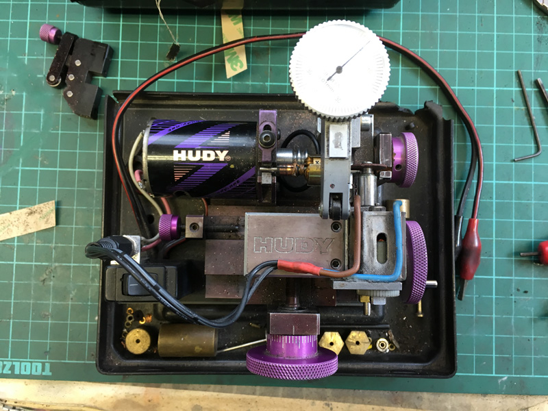
The Hackman Hudy "Hobby shaft grinding rig" looks sort of interesting. With care and patience it may possibly come fairly close. Send your arms to Wink, including a gift card, for a six pack of Boddington's and a few pounds. He will sit down, taking it easy, while knocking off the six of Boddington's and then tackle your armatures.


Good luck with that...


  • Cheater, Geary Carrier and Jesse Gonzales like this

#12 swodem

swodem

    Checkered Flag in Hand

  • Subscriber
  • PipPipPipPipPipPip
  • 1,176 posts
  • Joined: 29-October 14
  • Gender:Male
  • Location:Auckland, NZ

Posted 10 April 2019 - 12:11 AM

Dan

Yes, I could do this but not sure for an ES very high RPM armature it would be accurate enough.

2mm shaft for JK truer


Steve Meadows


#13 Wink Hackman

Wink Hackman

    Rookie Keyboard Racer

  • Full Member
  • Pip
  • 45 posts
  • Joined: 01-April 11
  • Gender:Male
  • Location:UK

Posted 10 April 2019 - 03:17 AM

It certainly takes care and patience. I've been using and perfecting the homemade rig for about 10 years. In that time I've ground many shafts for other racers and never had one returned.  I trashed a few of my own test pieces though. For sure a commercial concern with a centerless grinder should do better. 


If you do it yourself you need to support the shaft as rigidly as possible, as close to the end as possible, and in a way that minimises runout - i.e. in v-blocks or a ballrace. V-blocks should be best but you have to consider the cutting force trying to push the shaft up the slope of the block, so I went with a ballrace at the business end. It has to be changed every 10 armatures or so.


The toolpost grinder rig in the picture above is probably good enough for truing tyres, but not for armatures - it's only as accurate as the runout on the collet chuck. Sadly, in my experience they're not as good as you'd like – if you get them down to 0.02mm you're doing well, and that's not good enough.


  • Cheater likes this

#14 Dan Miller

Dan Miller

    Mid-Pack Racer

  • Full Member
  • PipPipPip
  • 128 posts
  • Joined: 07-March 09

Posted 10 April 2019 - 08:43 AM

Centerless grinding is not the method for the job.


Look at some YouTube videos of centerless grinding. It is an interesting process. That is not the technique required to reduce the diameter of a short length of your armature's shaft. You do want a center. Be it the armature sitting in a set of v-blocks or one end chucked and the other supported in a bearing. You want to know where the armature is when you grind the pinion step. As simple as the setup Wink has made, it has all the right elements to do a pretty reasonable job. Nice little project. No doubt about it.    


Centerless grinding means just that. The part sits on a blade and "floats" between a drive wheel and an abrasive wheel. That is how the shafts are made. You do not care where the center of a solid shaft is when you grind it. You want it round, straight, and taken to the correct diameter. Centerless grinding does just that.


Grinding on center is what you do to the finished armature to establish the pinion step or when you grind the outside diameter of the lamination stack.


  • Cheater, MSwiss and old & gray like this

#15 MSwiss

MSwiss

    Grand Champion Poster

  • IRRA National Director
  • PipPipPipPipPipPipPipPip
  • 25,623 posts
  • Joined: 16-April 06
  • Gender:Male

Posted 10 April 2019 - 09:58 AM

Wink,


Nice job on the arm shaft grinder.


Interesting way to do it, and probably the best way, on a compact machine.


Do you think steel disc, a bit smaller in diameter than the abrasive disc, between the screw head and disc, would add any worthwhile stiffness?


Mike Swiss
 
Inventor of the Low CG guide flag 4/20/18
IRRA® Components Committee Chairman
Five-time USRA National Champion (two G7, one G27, two G7 Senior)
Two-time G7 World Champion (1988, 1990), eight G7 main appearances
Eight-time G7 King track single lap world record holder

17B West Ogden Ave., Westmont, IL 60559, (708) 203-8003, mikeswiss86@hotmail.com (also my PayPal address)

Note: Send all USPS packages and mail to: 692 Citadel Drive, Westmont, Illinois 60559


#16 gotboostedvr6

gotboostedvr6

    Posting Leader

  • Full Member
  • PipPipPipPipPipPipPip
  • 2,314 posts
  • Joined: 19-July 11
  • Gender:Male
  • Location:Mt. Laurel

Posted 10 April 2019 - 01:15 PM

Yes. Also the abrasive dust must cause havoc.
David Parrotta

#17 MSwiss

MSwiss

    Grand Champion Poster

  • IRRA National Director
  • PipPipPipPipPipPipPipPip
  • 25,623 posts
  • Joined: 16-April 06
  • Gender:Male

Posted 10 April 2019 - 01:35 PM

I doubt the dust is much of an issue.

About a year ago, in a weekly Group F race, between heats, I balanced a 4002FK arm, inside the motor, with a Dremel with a 409 disc.

Between the 3-4 attempts, and cutting the strap off the bottom of the can, I probably removed 5-10 times more steel, than you would on reducing an arm shaft.

Regardless, if one one has the wherewithal to make a machine like the above, they probably can find their way to the vacuum cleaner store.

Mike Swiss
 
Inventor of the Low CG guide flag 4/20/18
IRRA® Components Committee Chairman
Five-time USRA National Champion (two G7, one G27, two G7 Senior)
Two-time G7 World Champion (1988, 1990), eight G7 main appearances
Eight-time G7 King track single lap world record holder

17B West Ogden Ave., Westmont, IL 60559, (708) 203-8003, mikeswiss86@hotmail.com (also my PayPal address)

Note: Send all USPS packages and mail to: 692 Citadel Drive, Westmont, Illinois 60559


#18 old & gray

old & gray

    Checkered Flag in Hand

  • Full Member
  • PipPipPipPipPipPip
  • 1,173 posts
  • Joined: 15-April 11
  • Gender:Male
  • Location:CT

Posted 10 April 2019 - 01:48 PM

Centerless grinding can have a problem of out of roundness on the trailing end of the piece. The process of pushing the piece past the wheel results in an unsupported area at the end.


Bob Schlain

#19 Wink Hackman

Wink Hackman

    Rookie Keyboard Racer

  • Full Member
  • Pip
  • 45 posts
  • Joined: 01-April 11
  • Gender:Male
  • Location:UK

Posted 10 April 2019 - 02:23 PM

My bad re. centerless grinding, I stand corrected.

Mike, at first I did back the cutoff disc with a steel disc exactly as you suggested, but I found that it made no difference provided I used the heavy duty Dremel cutoff disc.  Incidentally, the disc is pulled backwards onto the shaft – that way you can see what's happening.

The cutoff discs do clog with use though, so now I'm beginning to think of a Mk4 version using an axial CBN grinding wheel...

#20 wbugenis

wbugenis

    On The Lead Lap

  • Full Member
  • PipPipPipPip
  • 330 posts
  • Joined: 17-December 09
  • Gender:Male
  • Location:Brooklyn, NY

Posted 10 April 2019 - 02:35 PM

Lou Pirro of NY was doing it with two Dremels 10-12 years ago.

 
Lee Gilbert, too!! This was the method of choice before the armature manufacturers caught up to the fact that europsort racers needed a 6 tooth pinion (nowadays, a 5 tooth) requiring a bore of 1.5mm and sent out their armatures with a 1.5mm end for pinions.
 
Put a diamond disc on a Dremel and hold it against a rotating motor shaft. Cut and try until the pinion fits.
 Practice on some scrap motors until you can do it reliably.
 
It's like welding commutator tabs for those who were following some of the arm winding threads here.
 
Expect some failures but persistence will get you to where you need to be.
William Bugenis

#21 Rob Voska

Rob Voska

    Checkered Flag in Hand

  • Subscriber
  • PipPipPipPipPipPip
  • 1,073 posts
  • Joined: 12-April 08
  • Gender:Male

Posted 10 April 2019 - 04:10 PM

What is the best way to put a center on an arm shaft and have it dead center?


Then you would need a very good very small female center.


#22 Dan Miller

Dan Miller

    Mid-Pack Racer

  • Full Member
  • PipPipPip
  • 128 posts
  • Joined: 07-March 09

Posted 11 April 2019 - 11:22 AM

Putting a center on an armature shaft is not required for what we do to armatures. Not even for manual, single plane balancing an armature between magnets. 

Accurate chucking is or supporting in V-blocks is.
 
Why bother?

#23 Phil Hackett

Phil Hackett

    Grand Champion Poster

  • Advertiser
  • PipPipPipPipPipPipPipPip
  • 5,620 posts
  • Joined: 29-January 07
  • Gender:Male
  • Location:Formerly Aerospace Central

Posted 11 April 2019 - 02:27 PM

I keep seeing centerless grinding being mentioned as a method to grind down an armature! Stop!
 
Please read what Dan Miller says above. Trust him, centerless grinding is neither the suitable method or practical method for grinding armature shafts.


  • Rob Voska likes this

Click HERE to contact Sonic Products. The messenger feature on my Slotblog account has been disabled.

MACHINESIGN.JPG


#24 MSwiss

MSwiss

    Grand Champion Poster

  • IRRA National Director
  • PipPipPipPipPipPipPipPip
  • 25,623 posts
  • Joined: 16-April 06
  • Gender:Male

Posted 11 April 2019 - 06:27 PM

Put a diamond disc on a Dremel and hold it against a rotating motor shaft.


My bad re. centerless grinding, I stand corrected.Mike, at first I did back the cutoff disc with a steel disc exactly as you suggested, but I found that it made no difference provided I used the heavy duty Dremel cutoff disc.  Incidentally, the disc is pulled backwards onto the shaft that way you can see what's happening.The cutoff discs do clog with use though, so now I'm beginning to think of a Mk4 version using an axial CBN grinding wheel...


Wink,

I was wondering on the exact technique.

IOW, were you using the crossfeed, and relying on the edge of the disc, to remove material, or just setting the crossfeed once, and pulling the disc in, using the face of the disc. Obviously, it's the latter.

Have you tried a diamond-faced disc, as Bill B. decribed?

Dan, Phil, or anyone else, do you think the below would work to get the pinion spinning real concentrically?

Cut the 1.5mm step slightly undersize, and solder the pinion on the motor, like normal.

Using an 80p spur made of metal, or an 80p master, like on a gear checker, set a somewhat tight gear mesh, heat the pinion up, real well, and like you were slinging solder, turn on your power supply.

Would the pinion spin itself to concentricity, before the solder cooled?


Mike Swiss
 
Inventor of the Low CG guide flag 4/20/18
IRRA® Components Committee Chairman
Five-time USRA National Champion (two G7, one G27, two G7 Senior)
Two-time G7 World Champion (1988, 1990), eight G7 main appearances
Eight-time G7 King track single lap world record holder

17B West Ogden Ave., Westmont, IL 60559, (708) 203-8003, mikeswiss86@hotmail.com (also my PayPal address)

Note: Send all USPS packages and mail to: 692 Citadel Drive, Westmont, Illinois 60559


#25 Dan Miller

Dan Miller

    Mid-Pack Racer

  • Full Member
  • PipPipPip
  • 128 posts
  • Joined: 07-March 09

Posted 11 April 2019 - 07:35 PM

Mike,


I grind Scale pinion steps down to 1.485-1.49mm. The European guys will solder on the pinions and are aware of how gravity draws the solder down. They will then check the pinion with a really cool dial indicator jig thing to see where the pinion ended up. If not happy, I have watched them hit the pinion again as they turn the armature over another 30* or so. They then check the pinion again. I have seen them do this 4, 5, 6 times until they get the pinion to indicate where they want it.  


Your idea sort of makes sense but I cannot get past the idea that good integrity of the solder joint would be accomplished? Maybe I am not envisioning your idea clearly.


It also strikes me that you are pushing the pinion off to one side. As the solder cools and sets, you have no control of where it will end up because you can not predict where the shaft will be at the moment of solidification of the solder. What gap will it fill and will it be in the right position?


I will put my money on the Euro method of indicating until satisfied.


Electric Dreams Online Shop