Jump to content


Photo

CMF3 1249.2-Cc3 build sequence


  • Please log in to reply
20 replies to this topic

#1 Rick Moore

Rick Moore

    CMF3

  • Full Member
  • PipPipPipPipPip
  • 500 posts
  • Joined: 22-November 09
  • Gender:Male
  • Location:Tampa

Posted 18 December 2021 - 09:10 AM

1249.2-Cc3 Build Sequence, Prologue


The last build sequence thread I posted was for the 1237-Cb3+ way back in March 2017. While it is still generally valid as a base sequence for many of the single center main rail (sCMR) chassis designs in the 1237 Series, there have been enough changes in both design and build to warrant a new chassis build sequence post to bring “where I’m at” in my all-wire chassis frames up-to-date. In particular there are the “diverging main rail with iso-guide mount” (DMR/iG) chassis, the 1243, 1247, 1258, 1249, and 1256 designs (listed longest to shortest main rail length). Trying to overcome my well-honed propensity for procrastination, I figured if I was ever going to do another build sequence again I had better get it done with the 1249.2-Cc3 build…


If any poor souls are still trying to figure these weird wire chassis out, or worse take complete leave of their senses wanting to try to build one of these, this is where I would recommend you focus your efforts within the 1237-Series at this time, with the DMR/iG chassis. In that regard this thread should be of some benefit. Otherwise, for any actual value, at best, there is always just grabbing a favorite beverage and perusing the pics to kill some time for mild amusement.


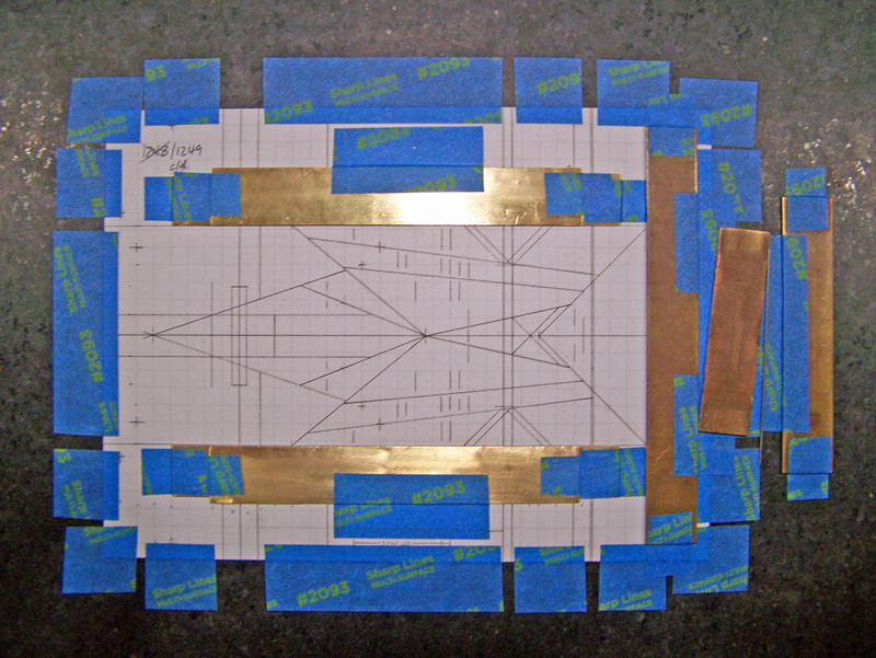
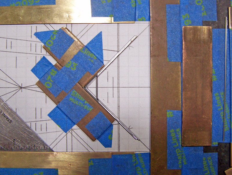
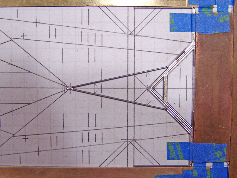
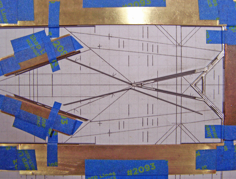
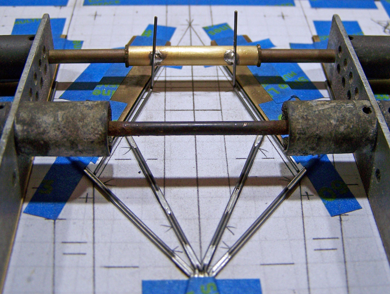
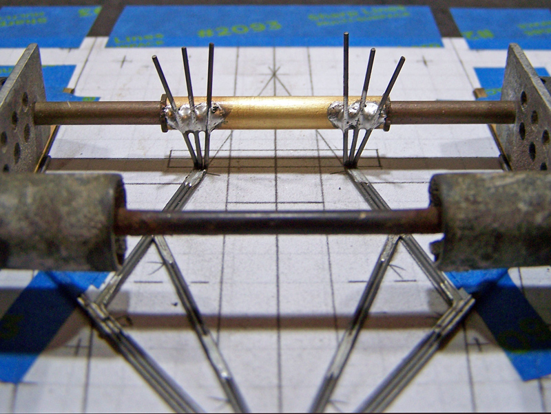
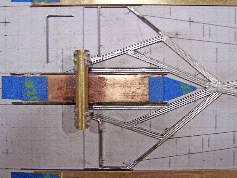
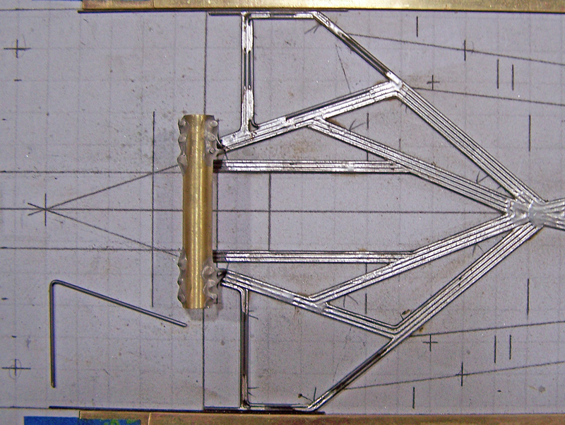
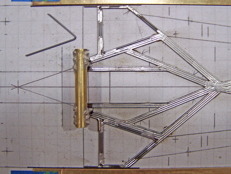
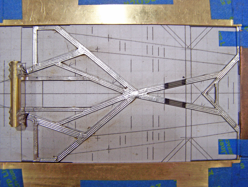
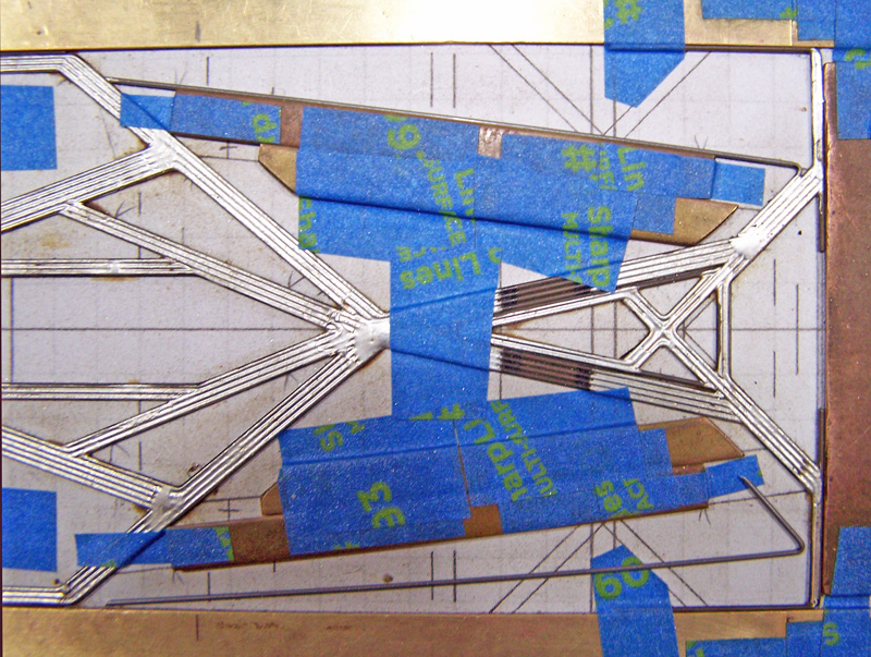
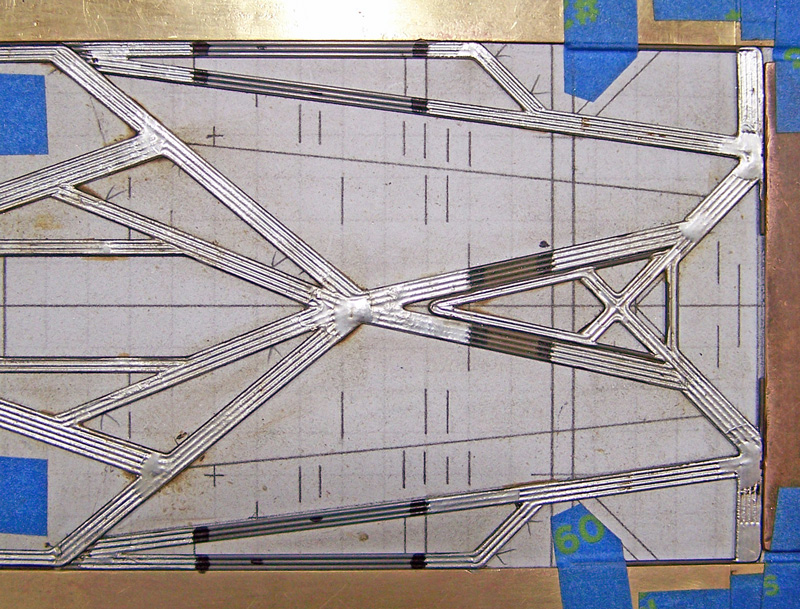
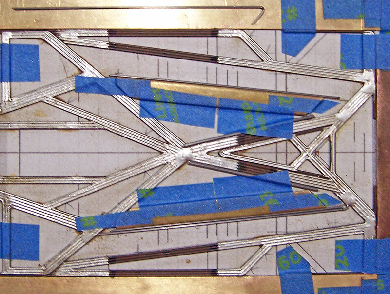
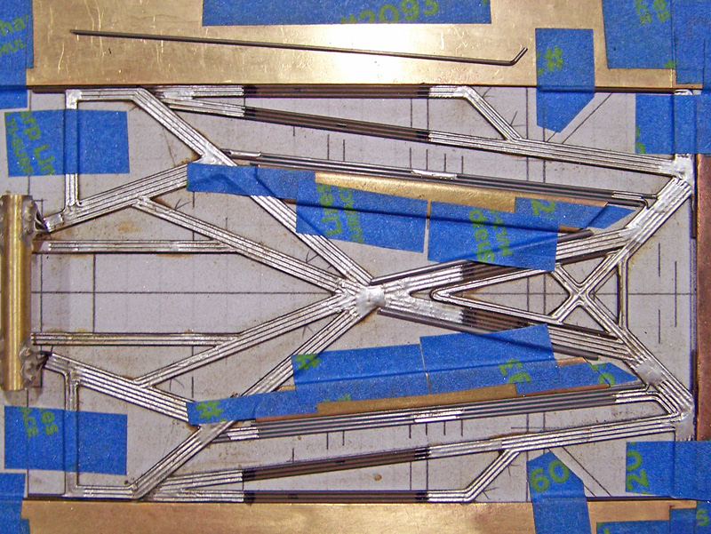
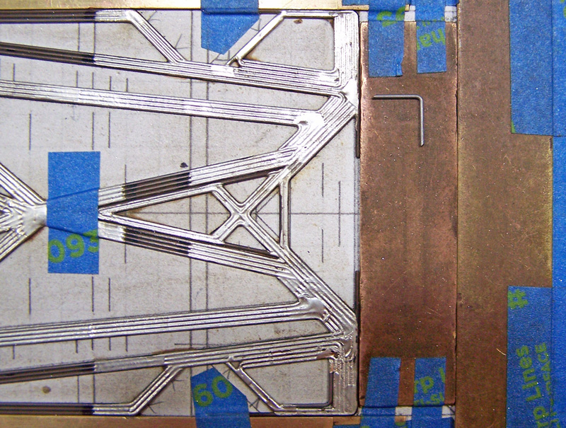
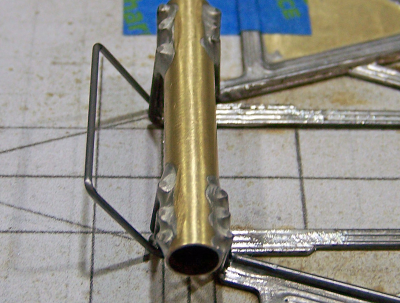
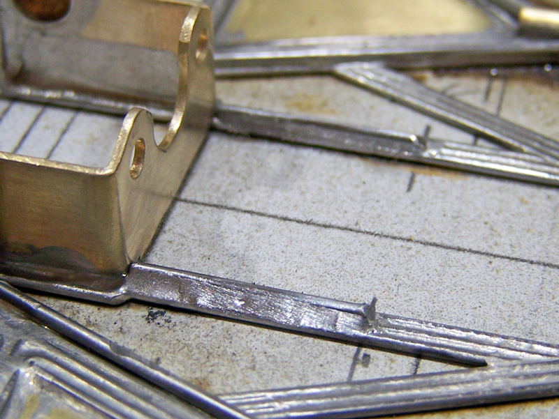
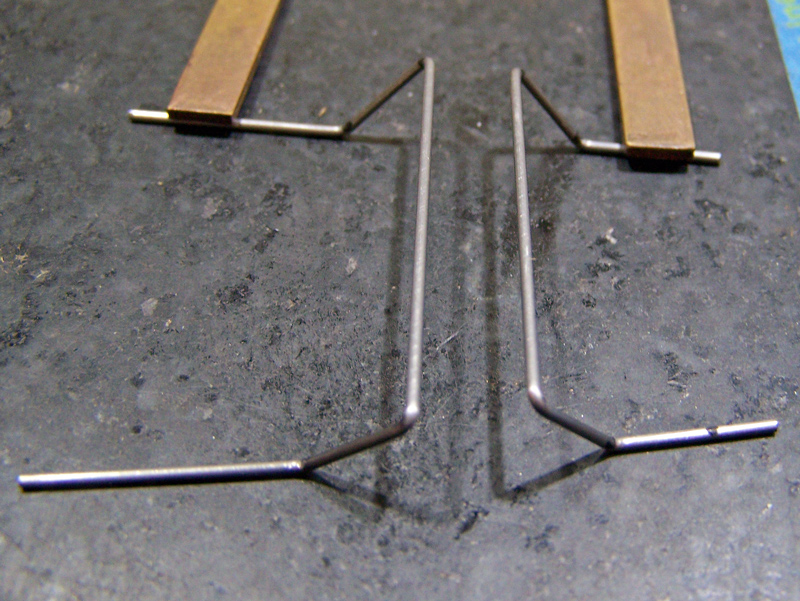
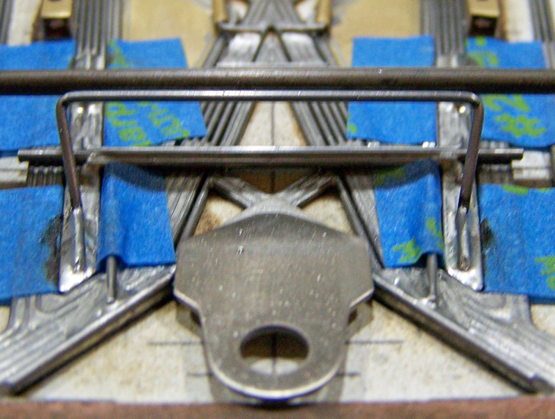
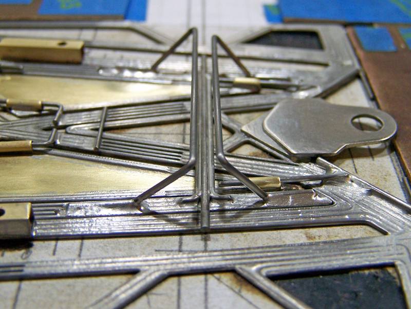
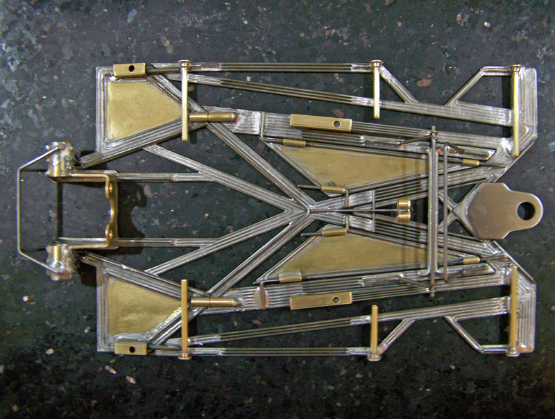
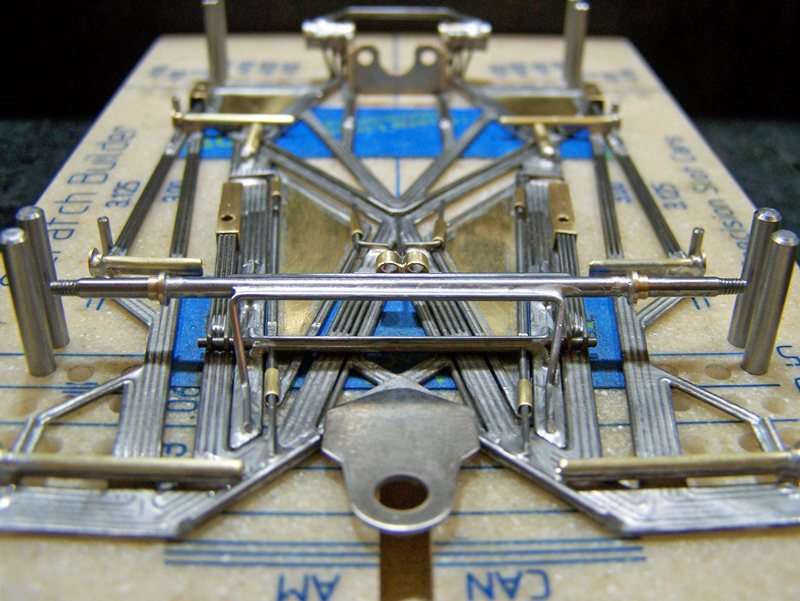
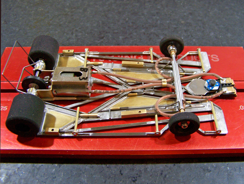
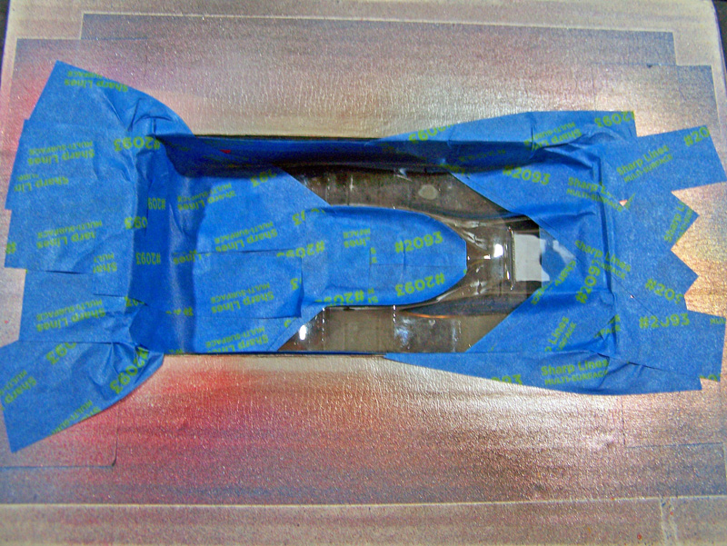
On the less technical side, and being a creature of questionable habits, my use of a graph paper design layout with well-worn pieces of brass, lots of blue tape, and the mandatory cameo appearance from my prehistoric Champion Align-O-Jig will once again be on full display. Off-camera, all the wires are still hand bent with the same pair of needle-nosed pliers I’ve had for twenty-five years.


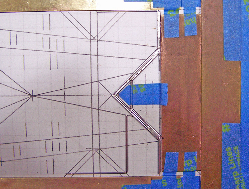
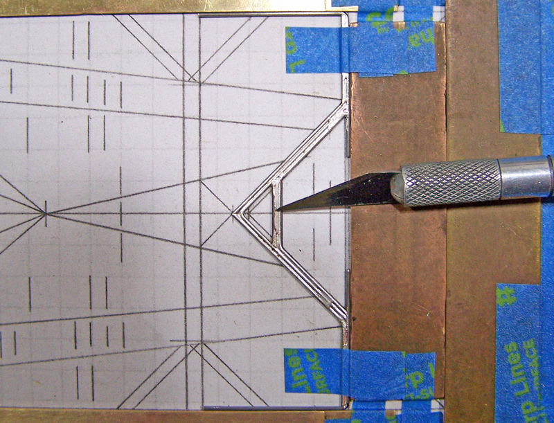
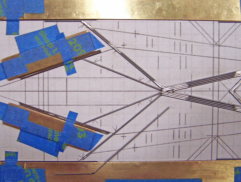
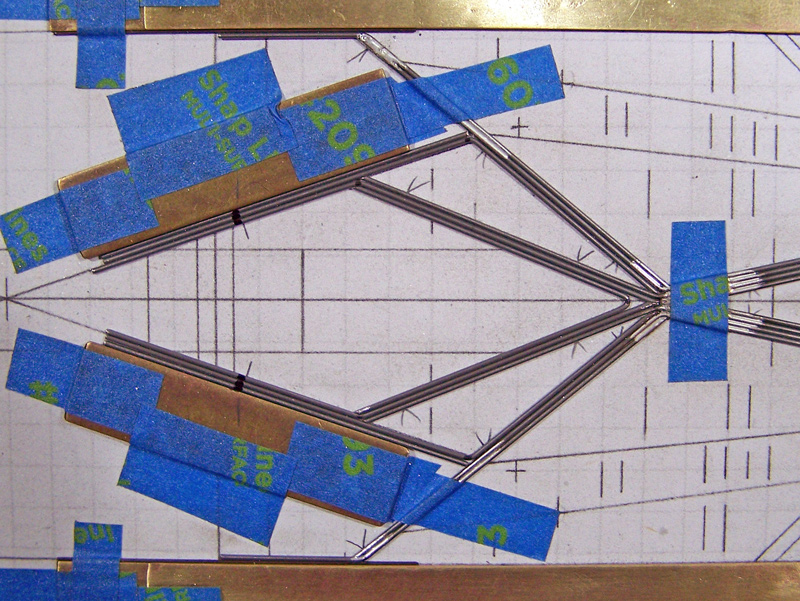
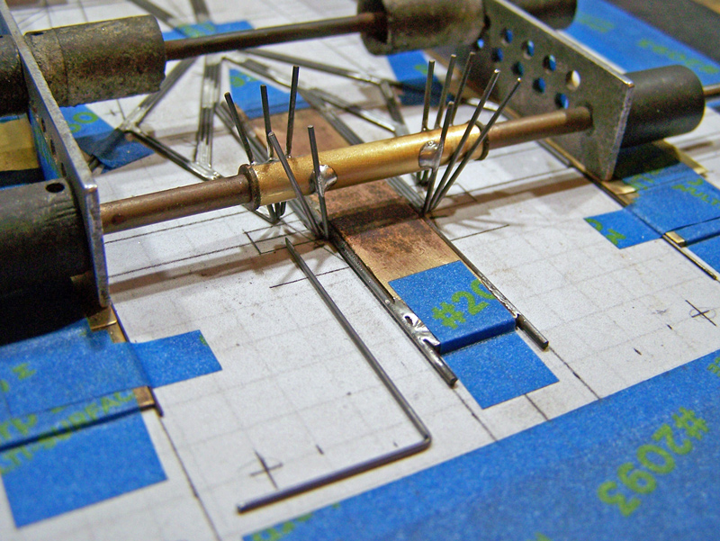
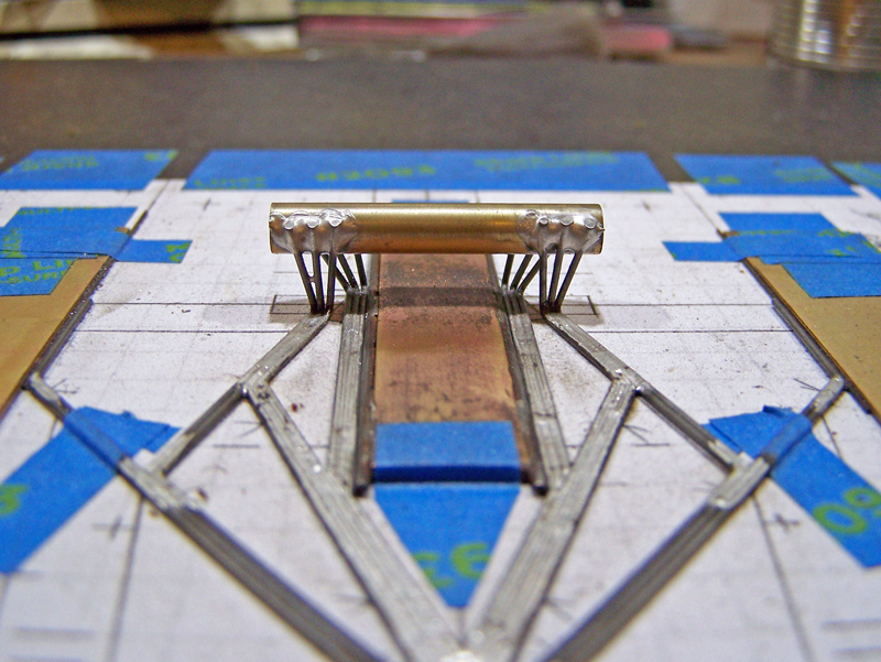
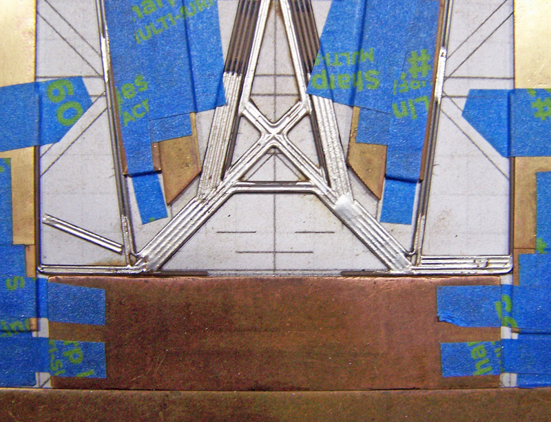
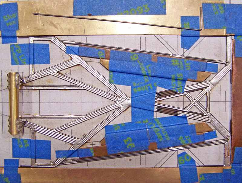
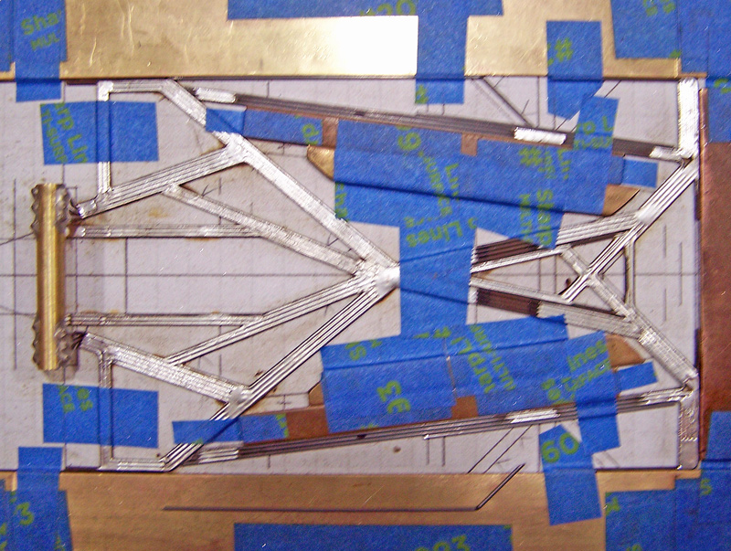
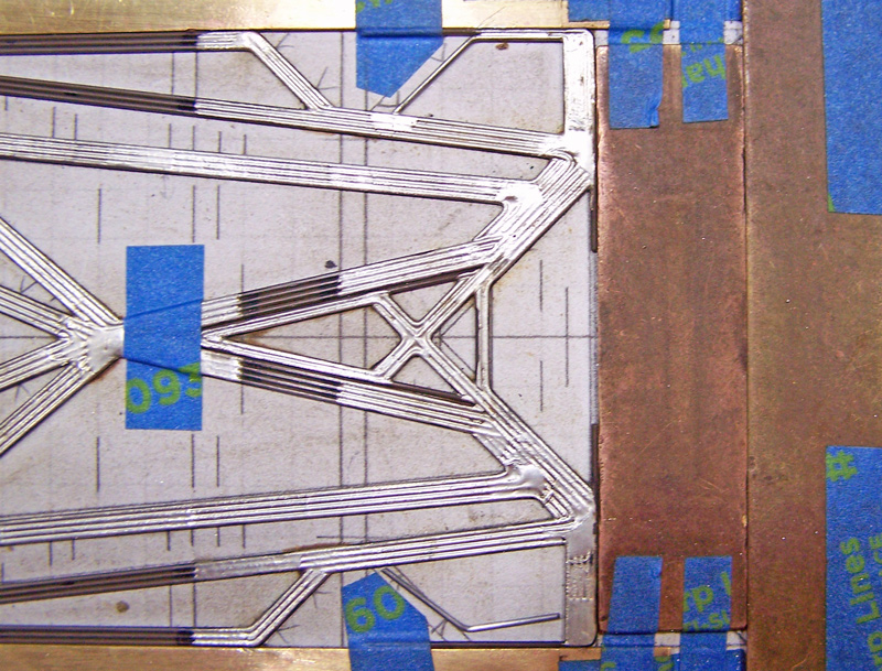
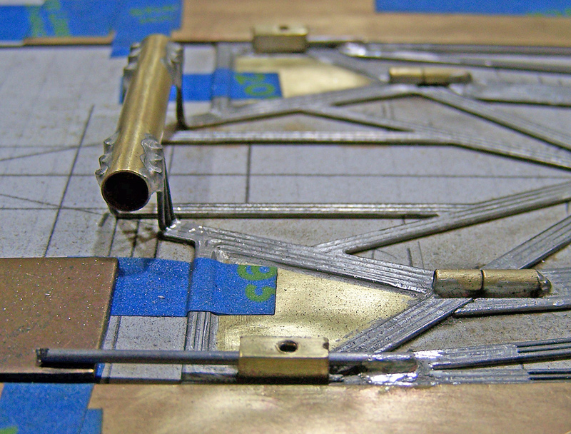
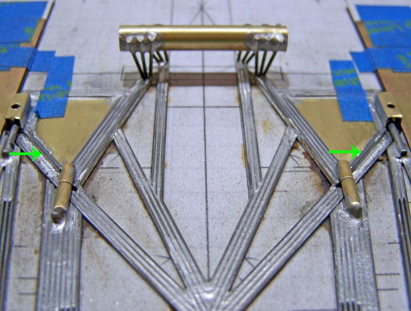
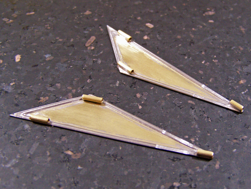
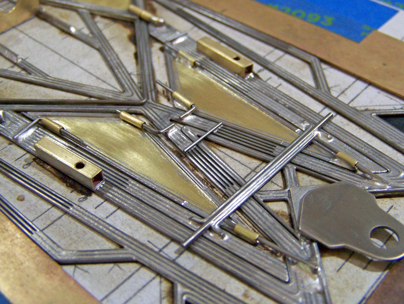
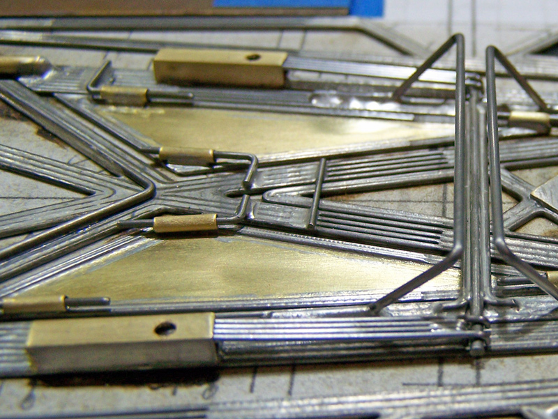
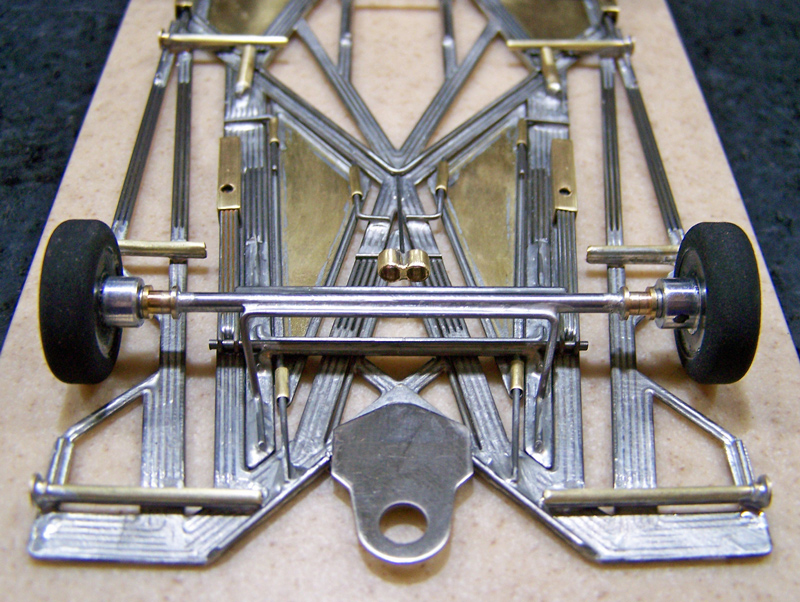
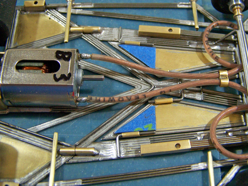
On the more technical side, the 1249.2-Cc3 build sequence will fill in some “holes” not covered in the 1237-Cb3+ post, that is in addition to the 1249 having the diverging main rails and the iso-guide mount. This 1249 is more appropriately a “c” dimensioned (4.875” RAx-GPC / 3.875” WB / 1.00” GL) chassis, and a CanAm class chassis, so it will include the dynamic pans. It will show the main frame’s wire layout sequencing which has changed slightly since the early 1237-Series builds. It also incorporates the “xxxx.2” front axle rail (FAR) layout with the accompanying torsion bar and variable spring wire (VSW) set-up. And the 1249 also has the extended version of the rear motor / drive assembly with the latest version of spine wires being used, and minor revision of the gear guard.


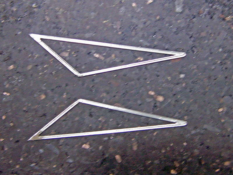
On the dysfunctional side, throughout I’ll try to go into more detail for better “visualization”, using more pictures per step for better clarity when deemed warranted (and when I remember to take the extra pics; at this point I pretty much build these things on auto-pilot, and any synaptic function is purely coincidental). Where there are two “mirror” wires being installed I’m still taking the picture with one wire in place and the other lying about somewhere in the picture, so, happy hunting.


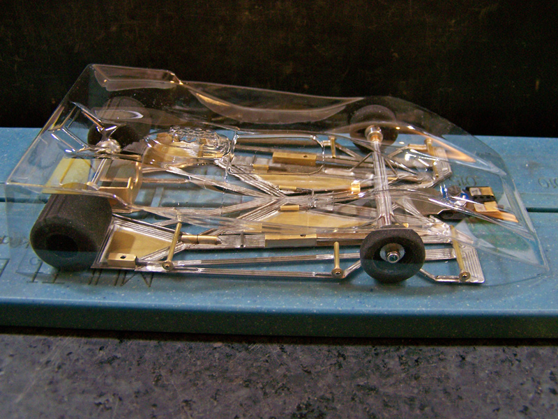
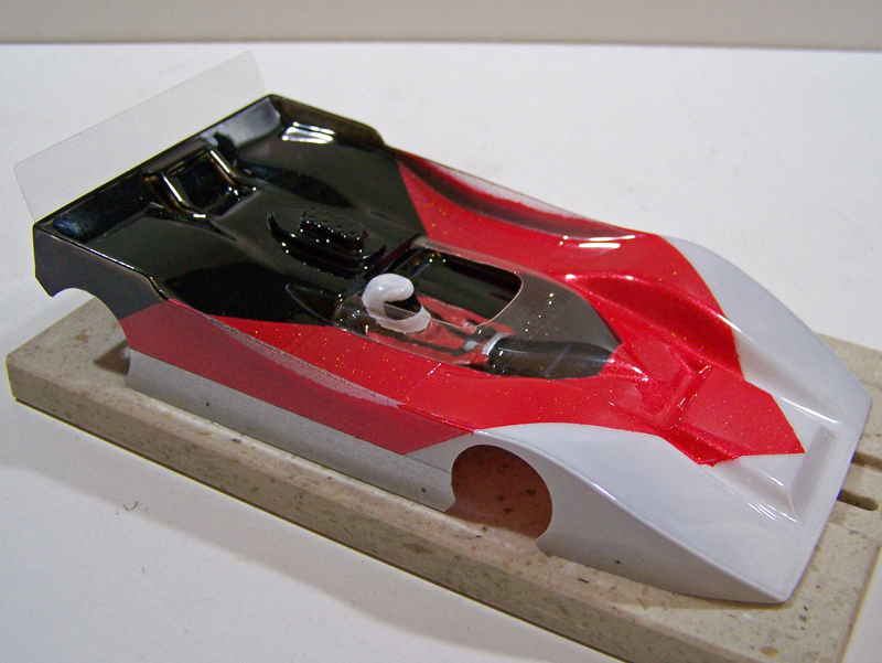
And for even more fun I’m also throwing in pics taking the 1249.2-Cc3 chassis through roller, including the sissy bar installation, and into its final ready-to-run status.


In other words, this should be a ridiculously long thread. Please try to contain your excitement. Adult beverages and/or medications may be required.


As usual, my apologies for any blur in the photos, as I still use the quickie Bend-Solder-Click process.


Descriptions are above each picture.


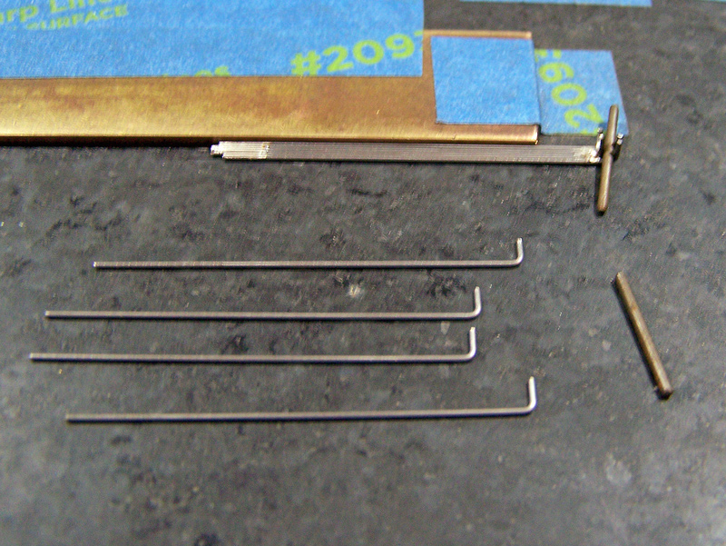
All wire is 0.032”, unless stated.


Side effects may include depression, anger, ambivalence, anti-social behavior, and in extreme cases violent activities and/or homicidal actions.


Rick / CMF3


#2 Rick Moore

Rick Moore

    CMF3

  • Full Member
  • PipPipPipPipPip
  • 500 posts
  • Joined: 22-November 09
  • Gender:Male
  • Location:Tampa

Posted 18 December 2021 - 09:17 AM

1249.2-Cc3 Build Sequence, Part 1 of 14


Section 1; Chassis Framing


Picture 1:  The 1249-c/d graph paper layout taped down; brass build “borders” in place (front plate positioned one ¾” brass strip plus one 0.032” wire forward of proximal chassis front line).


1249.2-Cc3-B001ae.jpg


Section 1.1; Front Spanner Assembly


Picture 2:  First two wires comprising the front spanner structure; one 1-bend (90-deg); one 2-bend wire to fit medial of first wire with side portions projecting 45-deg forward and with mid portion to set at front of guide tongue mount; sides long on both to be trimmed later.


1249.2-Cc3-B002ae.jpg


Picture 3:  First two front spanner wires soldered together.


1249.2-Cc3-B003ae.jpg


Picture 4:  First two front spanner wires positioned, 45-deg versus sides, position set with brass plates.


1249.2-Cc3-B004ae.jpg


Picture 5:  Chassis front border defined with second brass plate and a piece of 0.032” wire between (to be removed later). First two front spanner wires trimmed to length and positioned.


1249.2-Cc3-B005ae.jpg


Picture 6:  Brass plates (45-deg) removed. Two pieces of 0.032” wire (to be used for the fourth front spanner wires) are used as spacing along each side plate.


Third front spanner wires; two 1-bend (45-deg); soldered to lateral aspect of first two front spanner wires


1249.2-Cc3-B006ae.jpg


Picture 7:  The 0.032” spacing wire between the two brass plates defining the chassis front border is removed, with the rear-forward brass plate moved forward.


The 0.032” spacing wires along each side plate are removed, and used to make the fourth front spanner wires, two 1-bend wires (90-deg), defining the forward aspect of the front spanner and lateral aspects of the front wings; soldered to the forward aspect of the third front spanner wires, with excess lengths (lateral extending into wheel-wells, and forward extending into guide-well) to be trimmed later.


1249.2-Cc3-B007ae.jpg


Picture 8:  Last front spanner wire; a short piece of 0.039” wire to sit inside the forward aspect of the guide tongue mount “triangle” formed by the first and second front spanner wires.


1249.2-Cc3-B008ae.jpg


Section 1.2; Diverging Main Rails


Picture 9:  First diverging main rail (DMR) wires; two 1-bend; soldered (in place at the same time) to lateral aspects of front spanning structure and tack soldered at their intersection.


1249.2-Cc3-B009ae.jpg


#3 Rick Moore

Rick Moore

    CMF3

  • Full Member
  • PipPipPipPipPip
  • 500 posts
  • Joined: 22-November 09
  • Gender:Male
  • Location:Tampa

Posted 18 December 2021 - 09:23 AM

1249.2-Cc3 Build Sequence, Part 2 of 14


Picture 10:  Second DMR wire; one 1-bend (“V”), to fit medially inside of first DMR pair.


1249.2-Cc3-B010ae.jpg


Picture 11:  Two 0.020” wires set as spacing wires for lateral aspect of rear static pan framing. Two additional 0.032” spacing wires (to be used for wires in Picture 14) are placed one each medial of the 0.020” spacing wires.


Two brass plates with two 0.032” spacing wires each set to define lateral edge of lateral rear axle (L-RAx) tube support wires layout line.


Third DMR wires; two 1-bend; soldered to lateral rear aspects of first DMR wires, extending rearward to define the medial forward aspect (MFA) rails of the motor/drive assembly.


1249.2-Cc3-B011ae.jpg


Picture 12:  Fourth/final DMR wires; two 1-bend; soldered to lateral forward aspects of third DMR wires, extending rearward to define the lateral forward aspect (LFA) rails of the motor/drive assembly.


1249.2-Cc3-B012ae.jpg


Section 1.3; Rear Motor/Drive Assembly


Picture 13:  The 0.032” spacing wires beside the 0.020” spacing wires are removed, and used to make the next wire, two 1-bend; soldered to lateral aspect of the fourth DMR wire to define the lateral aspect of the motor/drive assembly LFA rails and rear static side pan framing.


1249.2-Cc3-B013ae.jpg


Picture 14:  The three pairs of lateral rear axle tube support (L-RAxS) wires are fabricated, two 1-bend, two 1-bend, two 0-bend; rear axle tube upright bends not made at this time.


Also the medial 1-bend (“V”) wire of the MFA rails is fabricated.


1249.2-Cc3-B014ae.jpg


Picture 15:  My prehistoric Champion Align-O-Jig (a subject unto itself, probably deserving of its own thread… nah, not really… but it has built a couple hundred chassis…) positioned, with 1.40” long 7/32” rear axle tube in place.


1249.2-Cc3-B015ae.jpg


Picture 16:  Note, all lateral rear axle tube support (L-RAxS) wires attach to front of the rear axle tube.


First L-RAxS wire; medial, two 1-bend (in chassis plane); axle tube upright bend configured (with slight lean to center, approximately abutting axle tube just lateral of projected motor bracket position); soldered to medial side of first MFA wire (Picture 11) and rear axle tube.


1249.2-Cc3-B016ae.jpg


Picture 17:  Second L-RAxS wire; medial, two 1-bend (in chassis plane); axle tube upright bend configured (with slight lean to outside, approximately midway of remaining axle tube); soldered to medial side of first LFA wire (Picture 12) and lateral side of first L-RAxS wire.


1249.2-Cc3-B017ae.jpg


Picture 18:  Third/final L-RAxS wire; medial, two 0-bend (in chassis plane); axle tube upright bend configured (with lean toward upper-outside axle tube corner); soldered to lateral side of second second L-RAxS wire.


All L-RAxS wires soldered to rear axle tube.


1249.2-Cc3-B018ae.jpg


#4 Rick Moore

Rick Moore

    CMF3

  • Full Member
  • PipPipPipPipPip
  • 500 posts
  • Joined: 22-November 09
  • Gender:Male
  • Location:Tampa

Posted 18 December 2021 - 09:29 AM

1249.2-Cc3 Build Sequence, Part 3 of 14


Picture 19:  Pre-fabricated MFA rail medial 1-bend (“V”) wire soldered to medial sides of first L-RAxS wires.


1249.2-Cc3-B019ae.jpg


Picture 20:  Dummy motor box (one 0.50” wide brass plate with two 0.047” wires, one flanking each side) positioned.

Note, dummy motor box is easily centered using two pieces of 0.75” wide and two pieces of 0.50” wide brass, one each (1.25”) per side medial of the 0.020” spacing wires.


1249.2-Cc3-B020ae.jpg


Picture 21:  Notes; the medial rear axle tube support (M-RaxS) wires also form the motor box; all M-RAxS wires attach to the rear of the rear axle tube tube.


First M-RAxS wires; two 1-bend (in chassis plane) with axle tube upright bend (configured with outward lean toward position of first/innermost L-RAxS wire); soldered to medial aspect of MFA V-wire and rear axle tube.


1249.2-Cc3-B021ae.jpg


Picture 22:  Second M-RAxS wires; two 0-bend (in chassis plane) with axle tube upright bend (configured with outward lean toward position of second/middle L-RAxS wire); soldered to lateral aspect of first M-RAxS wires.


1249.2-Cc3-B022ae.jpg


Picture 23:  Third/final M-RAxS wire; two 0-bend (in chassis plane) with axle tube upright bend (configured with outward lean toward position of third/outermost L-RAxS wire); soldered to lateral aspect of second M-RAxS wire.


1249.2-Cc3-B023ae.jpg


All M-RAxS wires soldered to rear axle tube. All excess length for L-RAxS and M-RAxS wires projecting above the rear axle tube are trimmed and Align-O-Jig removed


Note; Not clearly discernible in the pictures, all the rear axle tube support wires not only attach to the rear axle tube with varying angles laterally (side-to-side) as seen, but also with varying angles longitudinally (front-to-rear).


Picture 24:  Completed rear axle tube support wires, front view.


1249.2-Cc3-B024ae.jpg


Picture 25:  Completed rear axle tube support wires, rear view.


1249.2-Cc3-B025ae.jpg


Picture 26:  Additional LFA rail to L-RAxS rail tie-in wires, two 1-bend; soldered to medial aspects of respective rails.


1249.2-Cc3-B026ae.jpg


Picture 27:  First rear static pan framing wires, defining the rear of the static pan frames, two 1-bend wires, forming the rear aspect of the rear static pan framing; soldered to the third L-RAxS wire, and tack soldered to the wire in Picture 13.


1249.2-Cc3-B027ae.jpg


  • Greg Erskine likes this

#5 Rick Moore

Rick Moore

    CMF3

  • Full Member
  • PipPipPipPipPip
  • 500 posts
  • Joined: 22-November 09
  • Gender:Male
  • Location:Tampa

Posted 18 December 2021 - 09:35 AM

1249.2-Cc3 Build Sequence, Part 4 of 14


Picture 28:  (Blur…) Second rear static pan framing wires, two 1-bend wires; soldered to static pan frame’s interior aspects of first static pan framing wire and wire in Picture 13.


1249.2-Cc3-B028ae.jpg


Picture 29:  Third rear static pan framing wires, two 1-bend wires; soldered to interior aspects of second static pan framing wire and L-RAxS rail.


1249.2-Cc3-B029ae.jpg


Picture 30:  Fourth rear static pan framing wires, two 1-bend wires; soldered to interior aspects of third static pan framing wire and fourth DMR (LFA) wire.


1249.2-Cc3-B030ae.jpg


Picture 31:  Fifth/final rear static pan framing wires, two 1-bend wires; soldered to interior aspects of second and fourth static pan framing wires.


1249.2-Cc3-B031ae.jpg


Picture 32:  Chassis frame so far; front spanner assembly, diverging main rails, and rear motor/drive assembly framing completed.


1249.2-Cc3-B032ae.jpg


Section 1.4; iso-Guide Framing


Picture 33:  First guide tongue isolation mount (“iso-Guide”, or iG) framing wire, one 1-bend “V” wire, tack soldered to first front spanner wires, with minimal gap between second V-wire DMR wire.


1249.2-Cc3-B033ae.jpg


Picture 34:  (…kinda fuzzy…) Second iso-Guide framing wires, two 1-bend, soldered to apex of guide mount triangle (formed by front spanner wires) and first iso-Guide wire.


1249.2-Cc3-B034ae.jpg


Picture 35:  Third and fourth iso-Guide framing wires; third iG wires, two 1-bend, soldered forward aspect of second iG wire and lateral aspect of guide mount triangle; fourth iG wire, one 1-bend, soldered to medial forward aspects of second iG wire.


1249.2-Cc3-B035ae.jpg


Picture 36:  Completed iso-Guide framing.


1249.2-Cc3-B036ae.jpg


#6 Rick Moore

Rick Moore

    CMF3

  • Full Member
  • PipPipPipPipPip
  • 500 posts
  • Joined: 22-November 09
  • Gender:Male
  • Location:Tampa

Posted 18 December 2021 - 09:41 AM

1249.2-Cc3 Build Sequence, Part 5 of 14


Section 1.5; Side Pan Framing


Picture 37:  Medial edge of side pans defined with brass plates.


First side pan wires; two 1-bend; soldered to rear-lateral 45-deg aspect of the front spanner assembly / first DMR wire only.


1249.2-Cc3-B037ae.jpg


Picture 38:  Second side pan wires; two 0-bend; soldered to lateral aspect of the first side pan wires.


1249.2-Cc3-B038ae.jpg


Picture 39:  Two per side, short 0-bend, spacing/reinforcement wires are solder to the rear aspect of the front spanner (at front wing) assembly.


1249.2-Cc3-B039ae.jpg


Picture 40:  Third side pan wires; two 1-bend; soldered to lateral aspect of the second side pan wire and the spacing wires in Picture 39.


1249.2-Cc3-B040ae.jpg


Picture 41:  (…more blur…) Spacer wires (to be used for fifth side pan wires) positioned along forward lateral aspect of third side pan wire.


Fourth side pan wires (define the lateral aspect of the side pans and rear aspect of the front wheel wells); two 45-deg 1-bend; positioned (not soldered) in place.


1249.2-Cc3-B041ae.jpg


Picture 42:  Fifth side pan wires (spacer wires from picture 41); two 1-bend; soldered to forward lateral aspect of the third side pan wire and forward medial (45-deg rear of front wheel well) aspect of fourth side pan wires.


1249.2-Cc3-B042ae.jpg


Picture 43:  Sixth side pan wires; two 0-bend; soldered to medial aspect of the fourth side pan wires.


1249.2-Cc3-B043ae.jpg


Picture 44:  Seventh/final side pan wires; two 45-deg 1-bend; soldered to medial aspect of the fifth and sixth side pan wires, and to the lateral rear end of the third side pan wires.


1249.2-Cc3-B044ae.jpg


Picture 45:  Completed side pans.


1249.2-Cc3-B045ae.jpg


#7 Rick Moore

Rick Moore

    CMF3

  • Full Member
  • PipPipPipPipPip
  • 500 posts
  • Joined: 22-November 09
  • Gender:Male
  • Location:Tampa

Posted 18 December 2021 - 09:47 AM

1249.2-Cc3 Build Sequence, Part 6 of 14


Section 1.6; Buttress Rails


Picture 46:  First buttress rail wires; two 1-bend; soldered to lower rear-lateral 45-deg aspect of the front spanner assembly / first side pan wire only.


1249.2-Cc3-B046ae.jpg


Picture 47:  Second buttress rail wires; two 1-bend; soldered to upper rear-lateral 45-deg aspect of the front spanner assembly / first side pan wire and lateral side of first buttress rail wire.


1249.2-Cc3-B047ae.jpg


Picture 48:  Third buttress rail wires; two 1-bend; soldered to lateral aspects of the second buttress rail wire.


1249.2-Cc3-B048ae.jpg


Picture 49:  Fourth/final buttress rail wires; two 1-bend; soldered to medial aspects of the first buttress rail wire


1249.2-Cc3-B049ae.jpg


Picture 50:  Completed buttress rails.


1249.2-Cc3-B050ae.jpg


Section 1.7; Front Wings


Picture 51:  First front wing wires (defining the forward aspect of the front wheel wells); two 1-bend; soldered to medial aspect of the lateral portion of the fourth front spanner wire (Picture 7), and tack soldered to the fourth side pan wire.


1249.2-Cc3-B051ae.jpg


Picture 52:  Second front wing wires; two 1-bend; soldered to medial aspect of the first front wing wire and lateral aspect of the fourth side pan wire.


1249.2-Cc3-B052ae.jpg


Picture 53:  Third front wing wires; two 1-bend; soldered to lateral aspect of the second front wing wire and rear aspect of the fourth side pan wire.


1249.2-Cc3-B053ae.jpg


Picture 54:  Fourth/final front wing wires; two 1-bend; soldered to interior aspects of the first and third front wing wires.


1249.2-Cc3-B054ae.jpg


#8 Rick Moore

Rick Moore

    CMF3

  • Full Member
  • PipPipPipPipPip
  • 500 posts
  • Joined: 22-November 09
  • Gender:Male
  • Location:Tampa

Posted 18 December 2021 - 09:54 AM

1249.2-Cc3 Build Sequence, Part 7 of 14


Picture 55:  Completed front wings.


1249.2-Cc3-B055ae.jpg


Section 1.8; Main Frame Completion Steps


Step 1: Chassis frame is removed and excess wire lengths projecting into front and rear wheel wells trimmed.


Step 2: Main frame is given a bath to remove acid flux.


Step 3: Bottom of frame is brushed to remove any adhering paper and inspected for any solder pooling (removed if found).


Step 4: Excess solder is removed from top of frame.


Step 5: All main frame rails are re-soldered to “flood” all the rail wires for more uniform solder distribution.


Step 6: Main frame is given a second bath to remove acid flux.


Step 7: Bottom of frame is inspected again for any solder pooling (removed if found).


Step 8: Excess solder is again removed from top of frame.


Picture 56:  Completed main frame (prior to addition of front axle rails).


1249.2-Cc3-B056ae.jpg


Section 1.9; Front Axle Rails (FAR’s)


Picture 57:  Front axle rail (FAR) wires, two sets of four (eight), cut to length greater than medial side length of buttress rails, 0-bend (straight); wires soldered together at ends.


1249.2-Cc3-B057ae.jpg


Picture 58:  FAR 4x sets trimmed to fit medial of buttress rails, abutting the forward aspect of the rear motor/drive assembly, with a small but visible gap at front spanner and to the buttress rail (approximately 0.004 – 0.005”).


1249.2-Cc3-B058ae.jpg


Picture 59:  FAR’s fully soldered and flooded; FAR’s soldered to rear medial aspect of buttress rails. (For the 1249.2-Cc3 the buttress rails and FAR’s are soldered together rearward of the point 1.375” behind the front axle center line.)


1249.2-Cc3-B059ae.jpg


Section 1.10; Chassis Framing Completion


Picture 60:  Completed chassis frame (main frame plus front axle rails).


1249.2-Cc3-B060ae.jpg


Section 2; Chassis Superstructure


Section 2.1; iso-Guide Framing Up-Stop


Picture 61:  One 0.024” wire soldered atop main rails at rear of iso-guide structure (behind un-soldered portion of main rails) to act as up-stop (and effectively as “down-stop” for guide mount).


1249.2-Cc3-B061ae.jpg


Section 2.2; Rear Static Pans


Picture 62:  Two pieces 0.010” brass sheet, cut to fit and soldered into the rear-lateral framing of rear/motor drive assembly, making the lateral rear static pans.


1249.2-Cc3-B062ae.jpg


Section 2.3; Buttress Rail Articulations


Picture 63:  Rear of buttress rails (and FAR’s) shaved/filed to create small-visible gap between buttress rail end and rear motor drive assembly.


Tubing for buttress rail articulations; two pieces of 3/32” brass round tubing per side are cut, two each 0.20” (rear) and 0.25” (front); one of each length aligned with 0.062” wire; soldered individually, one 0.20” to the front of the chassis rear motor / drive assembly, and one 0.025” to the rear end of the buttress rail (overlapping but not soldered to the chassis rear motor / drive assembly).


1249.2-Cc3-B063ae.jpg


#9 Rick Moore

Rick Moore

    CMF3

  • Full Member
  • PipPipPipPipPip
  • 500 posts
  • Joined: 22-November 09
  • Gender:Male
  • Location:Tampa

Posted 18 December 2021 - 09:58 AM

1249.2-Cc3 Build Sequence, Part 8 of 14


Picture 64:  Buttress rail articulation 0.055” wire, passing through both tubes, biased to ride bottom of tubes; soldered to inside-front of forward articulation tube and buttress rail only.


1249.2-Cc3-B064ae.jpg


Section 2.4; Side Pan Restrictors


Picture 65:  Rear of side pan rails shaved/filed to create small-visible gap between side pan end and rear motor drive assembly.


Side pan restrictor boxes; two 1/8” square brass tubing, 0.35” long, with 0.062” hole drilled into top and screw (same as for motor mounting) tapped; soldered atop lateral edge of rear static pan framing.


1249.2-Cc3-B065ae.jpg


Picture 66:  Side pan restrictor wire; 0.055”, biased to set against lower-medial inside corner of side pan restrictor boxes; soldered to rear end of side pans.


1249.2-Cc3-B066ae.jpg


Section 2.5: Spine Wires


Picture 67:  First spine wires, two 0.039” 0-bend, soldered along entire length atop medial edge of lateral rear axle tube support rails from the rear axle tube uprights to the buttress articulation (green arrows).


1249.2-Cc3-B067ae.jpg


Picture 68:  Second spine wires, two 0.039” 0-bend, soldered along entire length atop medial edge of lateral forward aspect rails of the motor/drive assembly from the buttress articulation to the side pan restrictor box (green arrows).


1249.2-Cc3-B068ae.jpg


Picture 69:  Third/final spine wire, one 0.039” 1-bend, soldered (see note) atop medial edge of lateral forward aspect rails of the motor/drive assembly between the two buttress articulations. Note: Third spine rail not soldered at bend/apex approximately 0.20” back each side.


1249.2-Cc3-B069ae.jpg


Section 2.6; Dynamic Pans - Fabrication


Picture 70:  Two 3-sided dynamic pans are fabricated to fit between the lateral forward aspect rails of the motor/drive assembly, the diverging main rails, and the buttress rails.


Spacing:

The edge along the motor/drive lateral forward aspect rails uses a 3x 0.039” wire spacer.

The edge along the buttress rails uses a 1x 0.020” wire spacer.


First dynamic pan framing wires, two 0.024” 1-bend, formed, cut to fit and positioned along the buttress rail and main rails sides.


1249.2-Cc3-B070ae.jpg


Picture 71:  Second dynamic pan framing wires, two 0.024” 1-bend, soldered to “inside” of first dynamic pan framing wire along main rail side, and tack soldered to same at rear of buttress rail side.


1249.2-Cc3-B071ae.jpg


Picture 72:  Third/final dynamic pan framing wire, two 0.024” 1-bend, soldered to “insides” of first dynamic pan framing wire along buttress rail side, and second dynamic pan framing wire along motor/drive lateral forward aspect rail side.


1249.2-Cc3-B072ae.jpg


#10 Rick Moore

Rick Moore

    CMF3

  • Full Member
  • PipPipPipPipPip
  • 500 posts
  • Joined: 22-November 09
  • Gender:Male
  • Location:Tampa

Posted 18 December 2021 - 10:04 AM

1249.2-Cc3 Build Sequence, Part 9 of 14


Picture 73:  (…bbblur…) Completed dynamic pan frames.


1249.2-Cc3-B073ae.jpg


Picture 74:  (…bbbbblur…) Two pieces 0.010” brass sheet, cut to fit and soldered into the dynamic pan frames. Completed dynamic pans to be installed later.


1249.2-Cc3-B074ae.jpg


Section 2.7; Guide Tongue Mount and Side Stops


Picture 75:  (…blurblur…) The short piece of 0.039” wire soldered to the forward aspect of the “guide mount triangle” (Picture 8) has its top side ground/filed down to a thickness of 0.0355”.


A 5-sided 0.025” brass “sandwich” plate is cut to fit the main frame’s “guide mount triangle”; one side is tinned.


1249.2-Cc3-B075ae.jpg


Picture 76:  (…one blur leads to another…) Tinned (bottom) side of sandwich plate is soldered atop the main frame’s “guide mount triangle”, tinning the top side.


1249.2-Cc3-B076ae.jpg


Picture 77:  (fer cripes sake blur…) Bottom side of guide tongue is tinned where it will attach to the sandwich plate.


1249.2-Cc3-B077ae.jpg


Picture 78:  Guide tongue is soldered to the top of the sandwich plate; any excess solder atop the guide tongue is removed.


1249.2-Cc3-B078ae.jpg


Picture 79:  Guide lateral movement restrictor wires (“side stops”), two 0.039” 0-bend, soldered to top of medial edge of front spanner assembly’s 45-deg “guide-well” rail, from the guide tongue mount to the chassis front (with bevel cut). Note: Guide lateral movement restrictor wires also act as spine wires for the front spanner assembly.


1249.2-Cc3-B079ae.jpg


Section 2.8; FAR Torsion Bar


Picture 80:  (…enough blur…) Five component wires for torsion bar: one 0.047” 0-bend wire for center; two 1-bend wires for front of torsion bar with angle to match FAR angle; two 1-bend wires for rear of torsion bar with angle to match FAR angle. All wires at excess length.


1249.2-Cc3-B080ae.jpg


Picture 81:  Torsion bar component wires assembled.


1249.2-Cc3-B081ae.jpg


#11 Rick Moore

Rick Moore

    CMF3

  • Full Member
  • PipPipPipPipPip
  • 500 posts
  • Joined: 22-November 09
  • Gender:Male
  • Location:Tampa

Posted 18 December 2021 - 10:08 AM

1249.2-Cc3 Build Sequence, Part 10 of 14


Picture 82:  Torsion bar component 0.032” wires excess removed (not 0.047” center wire).


1249.2-Cc3-B082ae.jpg


Picture 83:  Torsion bar soldered to FAR’s, centered at front axle centerline; 0.047” center wire excess removed.


1249.2-Cc3-B083ae.jpg


Section 2.9; VSW Boxes


Picture 84:  Variable spring wire (VSW) boxes; two 1/8” square brass tubing, 0.625” long, with 0.062” hole drilled into top (5/32” behind front) and screw (same as for motor mounting) tapped; soldered atop buttress rail 0.875” behind front axle centerline.


1249.2-Cc3-B084ae.jpg


Section 2.10; VSW’s - Fabrication


Picture 85:  Variable spring wires (VSW’s), two sets of four (eight) 0.024” wire, cut to excess length greater than distance from torsion bar to rear of VSW box (1.75” minimum); all wires with 1-bend (approx.. 0.125” bent at approx. 90-deg) at one end. VSW two four wire sets arranged with middle wires behind and outside wires forward of 0.047” spacer wire (angled to approximate torsion bar angle to FAR on each side), and soldered together behind bends; rear of VSW’s soldered also.


1249.2-Cc3-B085ae.jpg


Picture 86:  Rear of VSW’s soldered to point matching front of VSW box; excess length behind VSW box removed; sides to fit in VSW box narrowed slightly. VSW front bends trimmed to rest on 0.047” wire and making contact with 0.047” wire only.


1249.2-Cc3-B086ae.jpg


Picture 87:  VSW’s bent at point just behind front of VSW box; angle of bend determined as snug with inside top of VSW box while resting on 0.047” wire portion of torsion bar (“zero slop”), but no downward tension force on torsion bar / FAR, with immediate tension apparent when FAR is pushed upward.


1249.2-Cc3-B087ae.jpg


Picture 88:  Completed VSW’s; to be removed, with final installation later.


1249.2-Cc3-B088ae.jpg


Section 2.11; Gear Guard and RAx Tube Spreader


Picture 89:  Gear guard; one 4-bend (one spanner, two risers, two footers), 0.79” wide spanner with 2x 90-deg bends in one plane (“U”); 0.50” risers (height measured from top of spanner to top of footer); riser-footer angles (in parallel planes) to place spanner within upper half of height of the rear axle tube; footer lengths trimmed to distance to motor bracket face line.


1249.2-Cc3-B089ae.jpg


Picture 90:  Gear guard footers soldered to lateral aspects of medial rear axle tube support / motor box rails.


1249.2-Cc3-B090ae.jpg


#12 Rick Moore

Rick Moore

    CMF3

  • Full Member
  • PipPipPipPipPip
  • 500 posts
  • Joined: 22-November 09
  • Gender:Male
  • Location:Tampa

Posted 18 December 2021 - 10:12 AM

1249.2-Cc3 Build Sequence, Part 11 of 14


Picture 91:  RAx-tube spreader; one 2-bend; soldered atop gear guard spanner and to lateral tops of RAx-tube.


1249.2-Cc3-B091ae.jpg


Picture 92:  Rear axle tube cut (cut-out equal to inside width of motor bracket).


1249.2-Cc3-B092ae.jpg


Section 2.12; Motor Bracket and Solder Rails


Picture 93:  Motor bracket (JKC82 / JK-D3F122) trimmed / modified.


1249.2-Cc3-B093ae.jpg


Picture 94:  Motor bracket aligned for angled motor mount (armature shaft at perpendicular with rear axle).


1249.2-Cc3-B094ae.jpg


Picture 95:  Motor bracket soldered to medial rear axle tube support / motor box rails, medial rear axle tube support upright, and rear axle tube.


1249.2-Cc3-B095ae.jpg


Picture 96:  Motor box solder rails; two 0.039” 0-bend, approximately 9/16” long, soldered to top of medial rear axle tube support / motor box rails from motor bracket forward. (“Solder rails” function to cradle the motor in the motor box, facilitate easier optional soldering of motor in place, and act as spine wires for the motor box.)


1249.2-Cc3-B096ae.jpg


Section 2.13; Dynamic Pans - Installation


Picture 97:  For each dynamic pan, three pieces of 1/16”d x 0.006” wall (“thin wall”) round brass tube soldered to dynamic pan framing, two along buttress rail (lateral / long) side, one at medial apex, all parallel with buttress rail side. Notes: Front tube must be able to clear torsion bar. Rear-outside tube positioned so hanger wire will be between buttress articulation and VSW box. Hanger for medial tube should be behind iso-guide up-stop wire.


1249.2-Cc3-B097ae.jpg


Picture 98:  For each dynamic pan, three hanger wires (0.032” wire). Notes: Front hanger wire is 0-bend, and must clear torsion bar. Rear-outside hanger wire is 1-bend 90-deg positioned to act as dynamic pan back-stop. Medial hanger is 1-bend 90-deg, positioned to act as dynamic pan front-stop.


1249.2-Cc3-B098ae.jpg


Section 2.14; Spanning Front Axle Uprights


Picture 99:  Tape applied to dynamic pans and buttress rails adjacent to front axle rails (FAR’s) forward and rearward of torsion bar. Side border brass plates reconfigured, and front “dummy” axle in place.


1249.2-Cc3-B099ae.jpg


#13 Rick Moore

Rick Moore

    CMF3

  • Full Member
  • PipPipPipPipPip
  • 500 posts
  • Joined: 22-November 09
  • Gender:Male
  • Location:Tampa

Posted 18 December 2021 - 10:17 AM

1249.2-Cc3 Build Sequence, Part 12 of 14


Picture 100:  Rear and front spanning front axle uprights, each 0.039” 4-bend (one spanner, two risers, two footers). Rear upright 1.50” wide spanner with 0.45” risers. Front upright 1.375” wide spanner 0.040” risers. (Note: Riser height measured from top of spanner to top of footer.) Risers angled inward to match width of FAR centers; footers angled to match angle of FAR’s and place the spanner at midpoint on dummy axle.


1249.2-Cc3-B100ae.jpg


Picture 101:  Rear spanning front axle upright soldered to FAR’s.


1249.2-Cc3-B101ae.jpg


Picture 102:  Front spanning front axle upright soldered to FAR’s.


1249.2-Cc3-B102ae.jpg


Picture 103:  Completed spanning front axle uprights (with dummy FAx and tape removed).


1249.2-Cc3-B103ae.jpg


Section 2.15; VSW’s - Installation


Picture 104:  Variable spring wires installed (into VSW box and resting on torsion bar center wire).


1249.2-Cc3-B104ae.jpg


Section 2.16; Pin Tubes


Picture 105:  Body mounting pin tubes, six total, three per side; all 1/16” brass tubing with 1/16” ID brass collar, atop 0.039” 1-bend (90-deg) mount wire.


1249.2-Cc3-B105ae.jpg


Picture 106:  Rear pin tubes: length trimmed to 0.875” (standard beading pin length); mount wire under pin tube trimmed to clear spine wires. Middle pin tubes: length trimmed to clear VSW’s. Front pin tubes: length trimmed to run to guide “side stop” wires.


1249.2-Cc3-B106ae.jpg


Picture 107: Rear pin tubes: mount wire soldered to rear of side pans so pin tube is between side pan restrictor and buttress articulation. Middle pin tubes: mount wire soldered to lateral and medial forward side pan rails. Front pin tubes: mount wire soldered to lateral wing rail, medial front wing rail, and front spanner (Note: Front pin tube mounts also act as additional “spine” wires).


1249.2-Cc3-B107ae.jpg


Section 2.17; Lead Wire Tubes


Picture 108:  Lead wire tube holder: one 2-bend 0.024” wire soldered to 2x 1/8” round brass tubing; soldered to forward apex of rear motor / drive assembly (Note: lead wire holder should be positioned so lead wires will not interfere with dynamic pan movement).


1249.2-Cc3-B108ae.jpg


#14 Rick Moore

Rick Moore

    CMF3

  • Full Member
  • PipPipPipPipPip
  • 500 posts
  • Joined: 22-November 09
  • Gender:Male
  • Location:Tampa

Posted 18 December 2021 - 10:22 AM

1249.2-Cc3 Build Sequence, Part 13 of 14


Section 2.18; Chassis Completion


Pictures 109 & 110:  Excess pin tubing and excess wire in guide well removed. Chassis completed.


1249.2-Cc3-B109ae.jpg


1249.2-Cc3-B110ae.jpg


Section 3; Runny Bits


Picture 111:  Rear ball bearings installed.


1249.2-Cc3-B111ae.jpg


Picture 112:  Front axle with 3/32” ID collars installed


1249.2-Cc3-B112ae.jpg


Picture 113:  Front wheels trued, spaced, and installed.


1249.2-Cc3-B113ae.jpg


Picture 114:  Rear axle with rear tires, trued, spaced, and installed


1249.2-Cc3-B114ae.jpg


Picture 115:  Guide, guide washers, guide nut, and guide clips installed; guide depth with braid checked. (This is where I take the roller pics for posting in the “CMF3 1237-Series Design and Build Progression” thread.)


1249.2-Cc3-B115ae.jpg


Picture 116:  Clear body trimmed and mounted.


1249.2-Cc3-B116ae.jpg


Picture 117:  Sissy bar; one 0.024” with 2-bends 1.25” apart. Sissy bar marked for rear axle tube bends.


1249.2-Cc3-B117ae.jpg


#15 Rick Moore

Rick Moore

    CMF3

  • Full Member
  • PipPipPipPipPip
  • 500 posts
  • Joined: 22-November 09
  • Gender:Male
  • Location:Tampa

Posted 18 December 2021 - 10:26 AM

1249.2-Cc3 Build Sequence, Part 14 of 14


Picture 118:  Sissy bar with rear axle tube bends, excess wire removed, and tack soldered to rear axle tube.


1249.2-Cc3-B118ae.jpg


Picture 119:  Sissy bar fully soldered to rear axle tube.


1249.2-Cc3-B119ae.jpg


Picture 120:  Sissy bar placement checked with tires and body returned.


1249.2-Cc3-B120ae.jpg


Picture 121:  Motor with pinion, crown gear, and lead wires installed.


1249.2-Cc3-B121ae.jpg


Picture 122:  Body painting time…


1249.2-Cc3-B122ae.jpg


Picture 123:  Body cut-outs (interior, wheel wells, and rear) bullet-proof, rear spoiler, trimming, and interior.


1249.2-Cc3-B123ae.jpg


Picture 124:  First check of the car’s total weight was under the CanAm class 100-gram minimum; two pieces of lead added to dynamic pans (topped with blue tape) to bring the mass up.


1249.2-Cc3-B124ae.jpg


Picture 125:  Final weight check, and done.


1249.2-Cc3-B125ae.jpg


#16 Rick Moore

Rick Moore

    CMF3

  • Full Member
  • PipPipPipPipPip
  • 500 posts
  • Joined: 22-November 09
  • Gender:Male
  • Location:Tampa

Posted 18 December 2021 - 10:28 AM

1249.2-Cc3 Build Sequence, Epilogue


The completed CMF3 1249.2-Cc3 chassis / car ready for its first laps.


1249.2-Cc3-B126ae.jpg


1249.2-Cc3-B127ae.jpg


1249.2-Cc3-B128ae.jpg


And there you have it. Now you know everything that goes into building one of these all-wire chassis frames I’ve designed, and now you also know there is no way in hell you’re ever going to waste this much time building a friggin’ slot car chassis like this. Similarly, this is why I get that have-you-lost-your-mind look whenever someone asks me how much it would cost for me to build one of these chassis for them, and they get the deer-in-the-headlights look when I answer them; after some awkward laughter I’ll point out all the other chassis builders out there (who have not completely lost their marbles) that build excellent chassis in a more reasonable time frame and offered at a much more acceptable price. More often than not I like to point out that if I can build all these weird (string of derogatory obscenities, though appropriate, omitted) chassis, they should be able to build whatever they want for themselves. And that’s all the fun of it anyway.


Have fun, slot car geeks.


Rick / CMF3


  • Chris Stemman, Tim Neja, Eddie Fleming and 2 others like this

#17 John Streisguth

John Streisguth

    Johnny VW

  • Full Member
  • PipPipPipPipPipPipPipPip
  • 5,638 posts
  • Joined: 20-November 08
  • Gender:Male
  • Location:Bangor, PA

Posted 18 December 2021 - 12:34 PM

Just....wow! :D


"Whatever..."

#18 Bill from NH

Bill from NH

    Age scrubs away speed!

  • Full Member
  • PipPipPipPipPipPipPipPip
  • 14,329 posts
  • Joined: 02-August 07
  • Gender:Male
  • Location:New Boston, NH

Posted 18 December 2021 - 04:25 PM

Rick, you ought to offer pre-bent kits for the cheapskates. Have you ever considered pre-tinning your wire? I know it will add time, but you might save some actual building time, plus then acid wouldn't rust the wire. This is a pretty good post; it must have taken as much time to post as it took building the chassis. I saved a "hot link" to the post so I can look at it in further detail. I was getting concerned about not using the "Align-O-Jig" until I saw photos 15 & 16. Am I going to build one? Well, no, when I die, I don't want it to be while chassis building.  :laugh2: Besides, I don't have any local tracks to run it on if I did. 


Bill Fernald
 
I intend to live forever!  So far, so good.  :laugh2:  :laugh2: 

#19 Pablo

Pablo

    Builder

  • Administrator
  • PipPipPipPipPipPipPipPip
  • 18,370 posts
  • Joined: 20-February 06
  • Gender:Male
  • Location:Cleveland, Tennessee

Posted 18 December 2021 - 10:16 PM

Rick, I appreciate your "sickness"  :)  in a good way  :crazy:


I miss Joey


Paul Wolcott


#20 Rick Moore

Rick Moore

    CMF3

  • Full Member
  • PipPipPipPipPip
  • 500 posts
  • Joined: 22-November 09
  • Gender:Male
  • Location:Tampa

Posted 20 December 2021 - 10:50 AM

John, that’s what I say every time I finish one of these chassis and think about how much time out of this lifetime I’ve spent building them… some might even say “wasted”, though that term would probably be more accurate describing what I’d probably do if I wasn’t wasting time with slot cars…  :crazy:


Bill, I still have that 60’s mentality that a chassis is only good for a week or two, so any diminished aesthetic value from rusting is the chassis’ fault for still being around. While I have always appreciated the artistry of the bright-n-shiny chassis others may build, for me it is function first and the next chassis build second… Took me years before I’d even bother giving the chassis a bunch of baths during the build (don’t expect any of these to go into my tumbler either). As for a pre-bent kit, that would take me almost as long as the entire build, the soldering being the easy part; the solder is what holds it all in place while I bend-shape-fit the next wire; I’d just wind up using even more blue tape… With that many wires and pieces it wouldn’t be much of a “savings” either, I’d still charge an arm-and-a-leg... Similarly, that would be a lot of pre-tinning, and might not offer any time savings at all. I don’t even have any idea how many 36” lengths of wire (I already buy it in bulk) I use in a chassis anymore; I used to count the lengths and number of wires in a chassis, but it was kind of depressing; not much different than when I used to count how many X-ray exams I’d do at work during my shifts… Too many in either case. Some things are best left to speculation, ignorance being bliss (a stupid expression, I don’t know about you but I can think of things that offer a lot more “bliss” than ignorance  :rolleyes:  ).


Pablo! A chronic and progressive illness in many cases. Possibly qualifies as a paraphrase of George Carlin, “One man’s sickness is another man’s well-being.” I miss Joey too. Miss those puppy hugs. A lot. All the time. Especially whenever I have pizza, which I still like and is still sort of fun at least; with Joey having pizza used to be exciting!   ;)


  • Bill from NH likes this

#21 NateT

NateT

    On The Lead Lap

  • Full Member
  • PipPipPipPip
  • 225 posts
  • Joined: 15-December 19
  • Gender:Male
  • Location:Strathroy, Ontario

Posted 14 January 2022 - 06:03 AM

brilliant.


Nate Talaskavich
 
NateTalaskavich@gmail.com


Track Owner at ONO Raceway in London Ontario
  
 ONO Slot car club Facebook page


Electric Dreams Online Shop