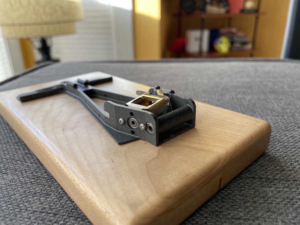
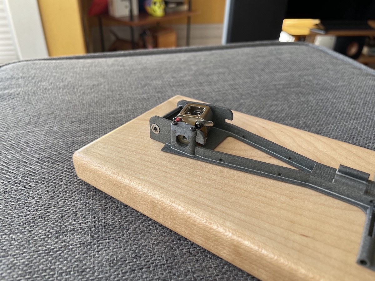
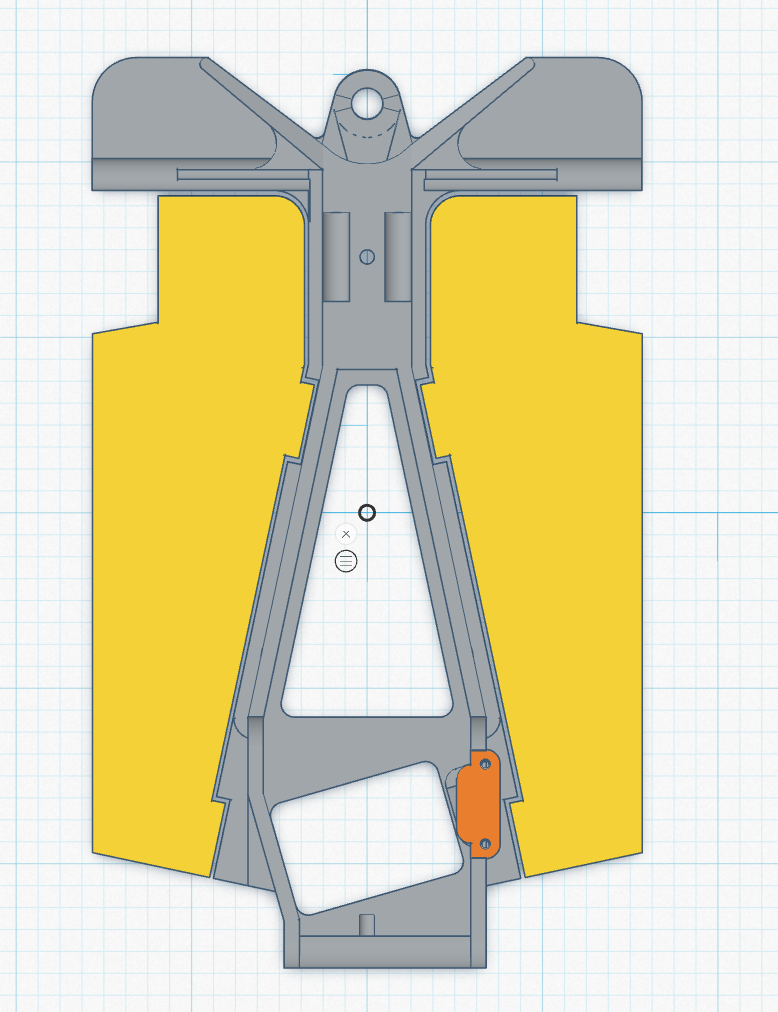
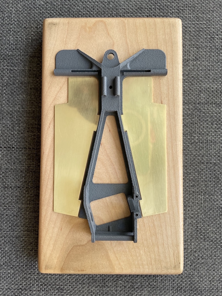
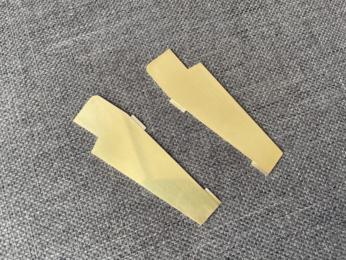
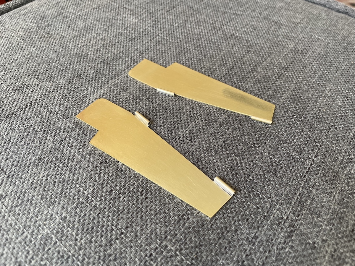
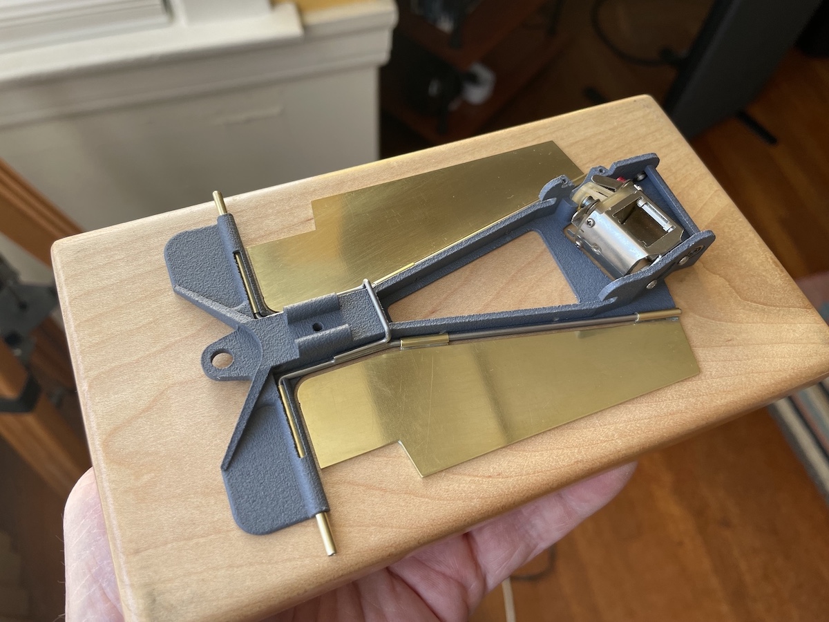
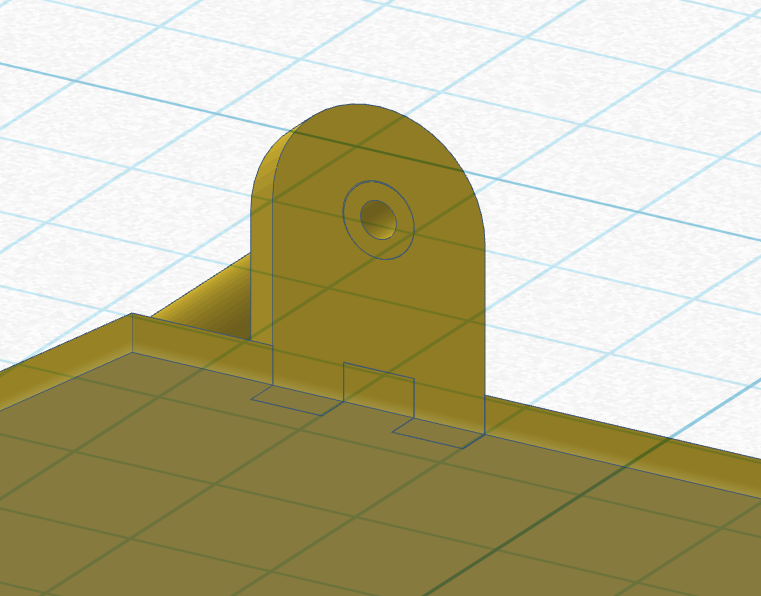
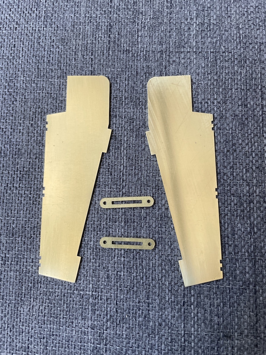
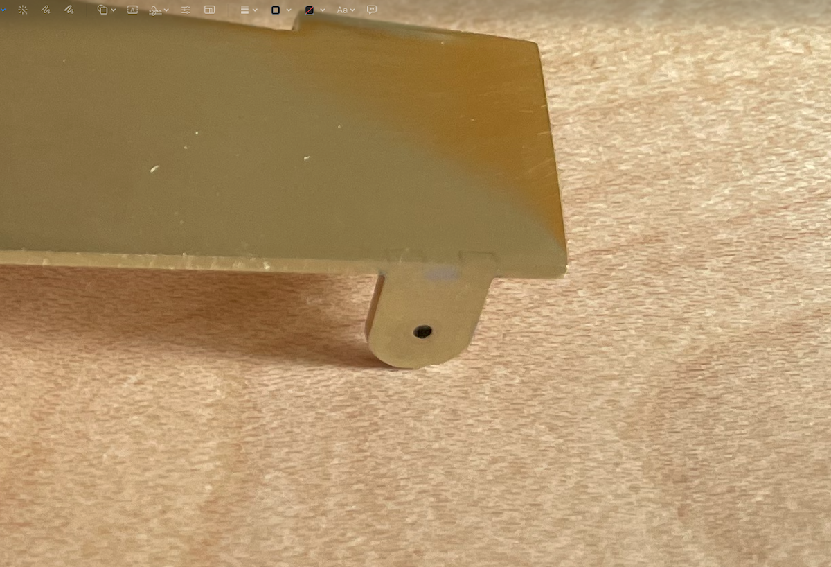
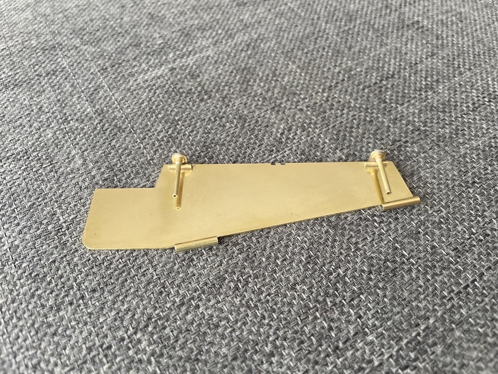
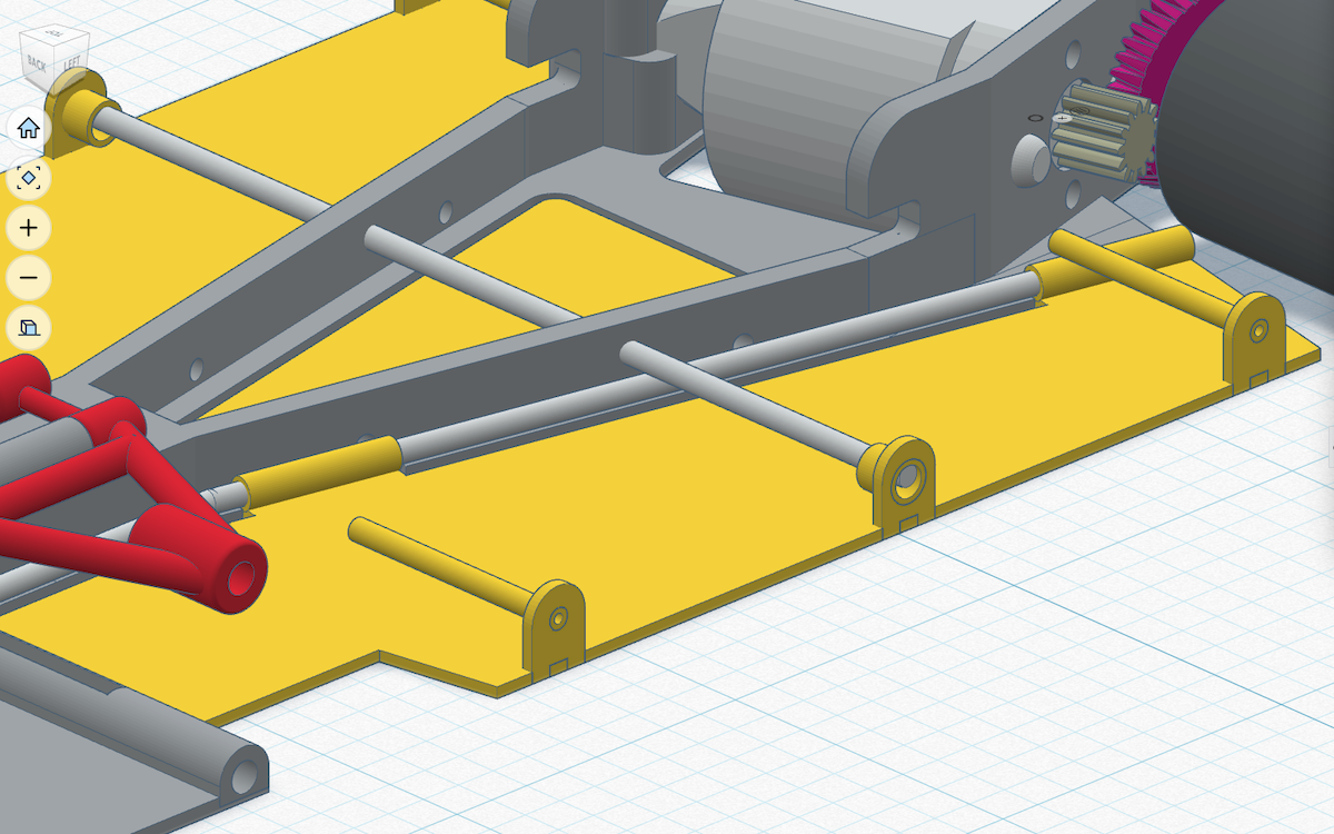
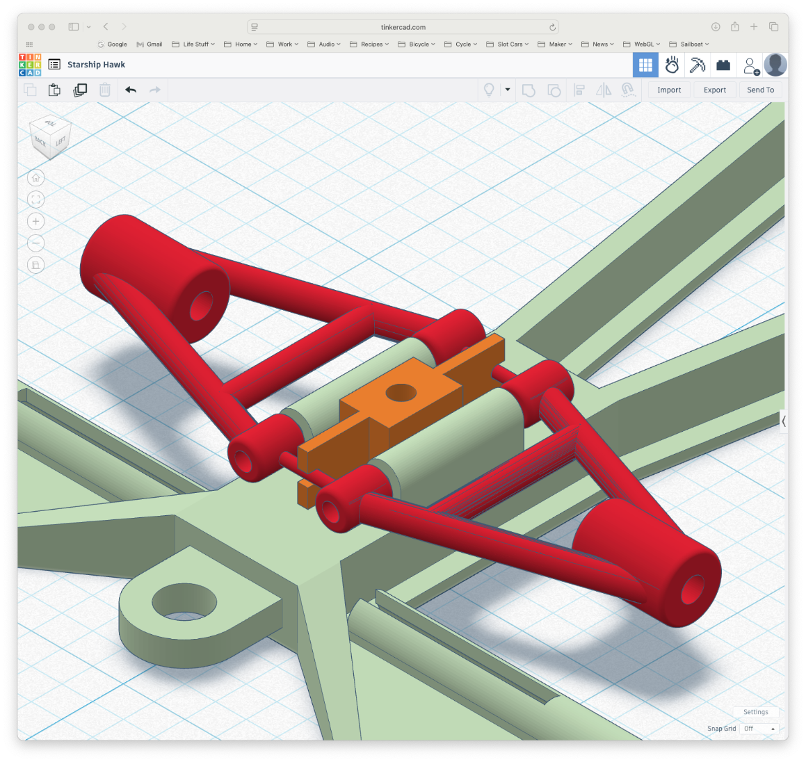
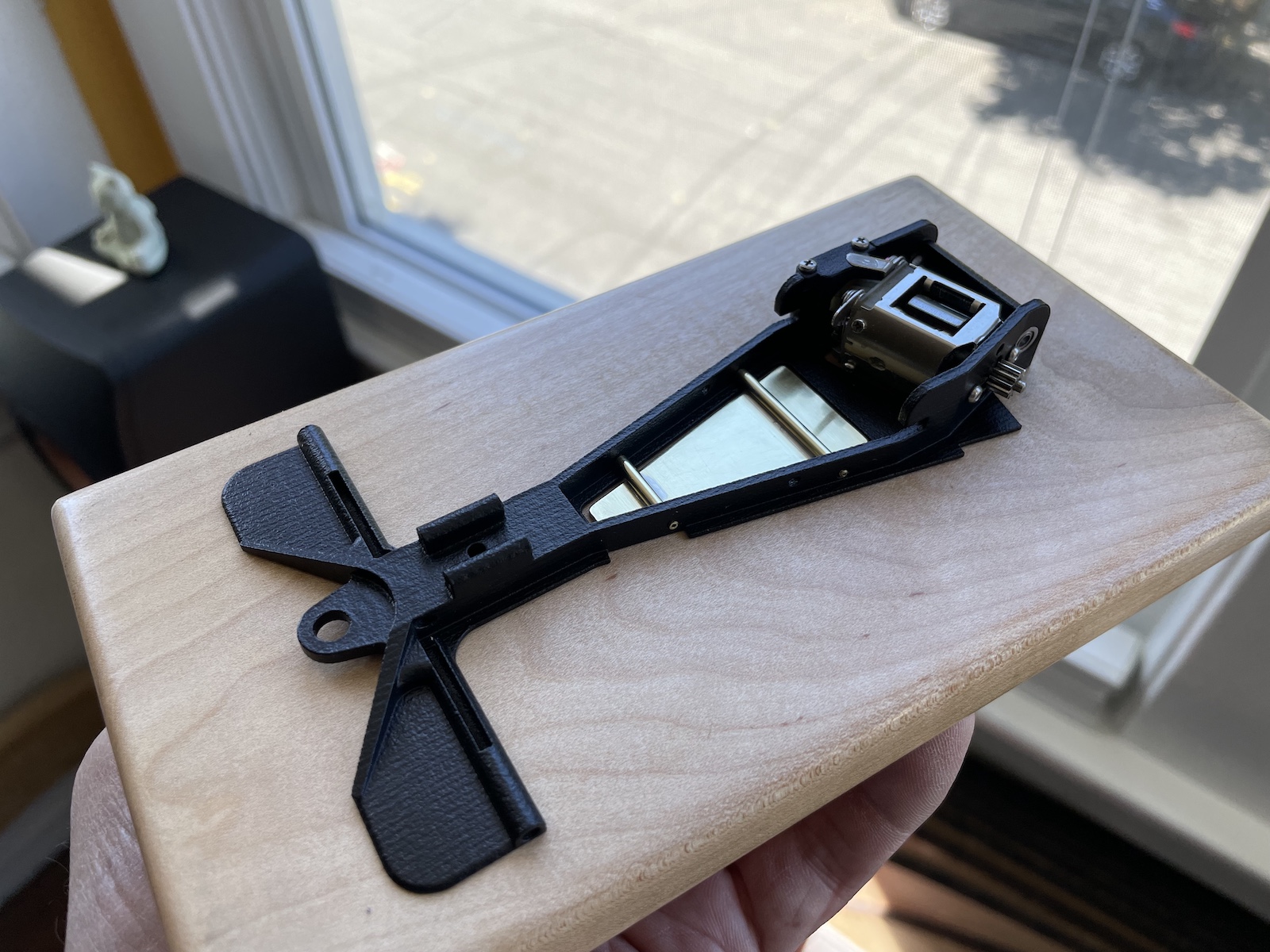
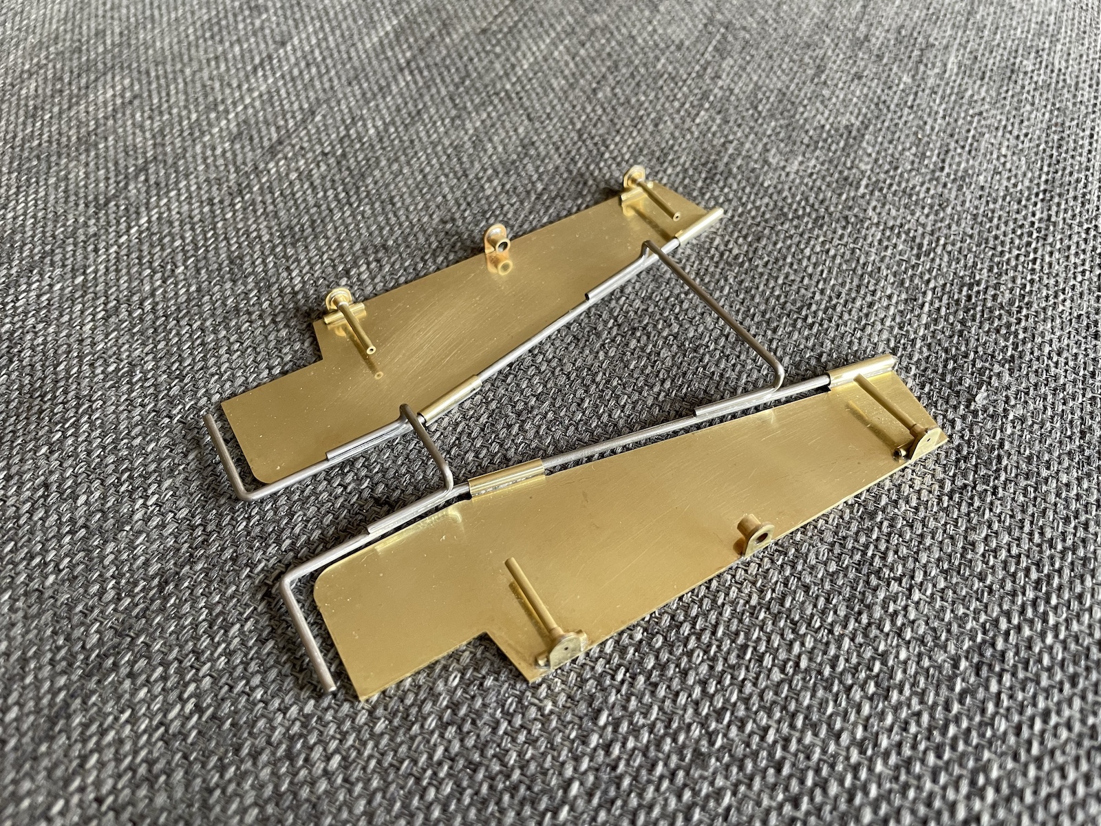
In an earlier post, Martin and I created a new interpretation of the iconic Starship chassis that combines classic brass and wire construction with modern 3D printed parts: https://slotblog.net/topic/105188-something-borrowed-something-new. It was a very fun collaboration but I wanted to push the boundaries a bit further. Specifically, the choice of a sidewinder layout meant a minimum of 7/8” rear tires whereas modern flexi chassis are running much smaller tires. So I embarked to return to the original Starship’s anglewinder configuration. The first step was to widen the rear triangle from the sidewinder’s slim 20 degree angle to 24 degrees which I think is pretty much in the ballpark with the original Starship. I also dropped the rear axle to allow .050” clearance with .720 tires.
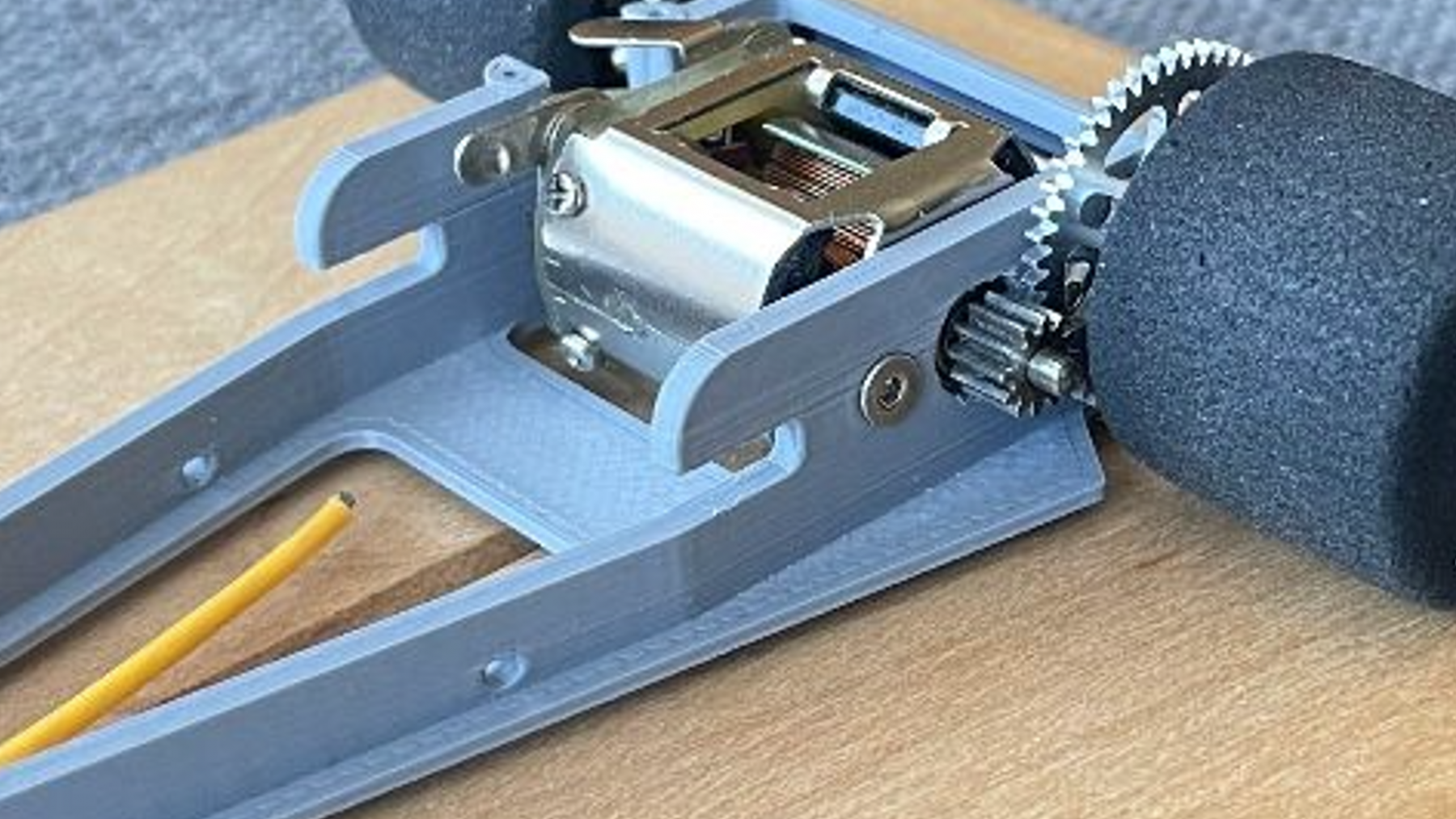
Now the elephant in the room is that the motor can’t be soldered to the motor box hence I had to engineer a way around what Pablo calls the dreaded bunny hop. The solution begins with an inset left rear bearing so that it lies under the plane of the motor box exterior. And this allows the use of not one but TWO motor mounting bolts as the rear one simply rides over the bearing. I’ve provisioned the chassis with holes for the motor’s top and bottom screws as well but I don’t think this belt and suspenders approach is really necessary.