
I realize there are probably several examples on the chassis building forum, but with a dial-up ISP, that's pretty much off limits
 !
!I would appreciate any and all suggestions.

|

Village Luddite

Posted 31 March 2009 - 08:38 PM
!I am not a doctor, but I played one as a child with the girl next door.
Posting Leader

Posted 31 March 2009 - 09:56 PM

Grand Champion Poster

Posted 01 April 2009 - 05:55 AM
Jim "Butch" Dunaway
I don't always go the extra mile, but when I do it's because I missed my exit.
All my life I've strived to keep from becoming a millionaire, so far I've succeeded.
There are three kinds of people in the world, those that are good at math and those that aren't.
No matter how big of a hammer you use, you can't pound common sense into stupid people, believe me, I've tried.
On The Lead Lap

Posted 01 April 2009 - 06:08 AM

Grand Champion Poster

Posted 01 April 2009 - 07:09 AM
Joe "Noose" Neumeister
Sometimes known as a serial despoiler of the clear purity of virgin Lexan bodies. Lexan is my canvas!
Noose Custom Painting - Since 1967
Chairman - IRRA® Body Committee - Roving IRRA® Tech Dude - "EVIL BUCKS Painter"
"Team Evil Bucks" Racer - 2016 Caribbean Retro Overall Champion
The only thing bad about Retro is admitting that you remember doing it originally.
Grand Champion Poster

Posted 01 April 2009 - 07:16 AM
Anthony 'Tonyp' Przybylowicz
5/28/50-12/20/21
Requiescat in Pace
Posting Leader
Posted 01 April 2009 - 07:17 AM
Dennis,
Do you solder the three side rails together all the way from front to back or just on the ends?
Do you have pics of one of these designs?


Grand Champion Poster
Posted 01 April 2009 - 07:34 AM
Jim "Butch" Dunaway
I don't always go the extra mile, but when I do it's because I missed my exit.
All my life I've strived to keep from becoming a millionaire, so far I've succeeded.
There are three kinds of people in the world, those that are good at math and those that aren't.
No matter how big of a hammer you use, you can't pound common sense into stupid people, believe me, I've tried.
Posting Leader
Posted 01 April 2009 - 07:46 AM


Village Luddite
Posted 02 April 2009 - 09:25 AM
I am not a doctor, but I played one as a child with the girl next door.
Posting Leader
Posted 02 April 2009 - 10:04 AM

The Dokktor is IN

Posted 02 April 2009 - 12:01 PM

Philippe de Lespinay
Race Leader

Posted 02 April 2009 - 02:36 PM

Village Luddite
Posted 02 April 2009 - 08:41 PM
I am not a doctor, but I played one as a child with the girl next door.
Grand Champion Poster
Posted 03 April 2009 - 05:38 AM
Jim "Butch" Dunaway
I don't always go the extra mile, but when I do it's because I missed my exit.
All my life I've strived to keep from becoming a millionaire, so far I've succeeded.
There are three kinds of people in the world, those that are good at math and those that aren't.
No matter how big of a hammer you use, you can't pound common sense into stupid people, believe me, I've tried.
Posting Leader
Posted 03 April 2009 - 02:36 PM
Have you ever built one of these chassis where the center weight is NOT connected to the pans?
Checkered Flag in Hand

Posted 03 April 2009 - 04:57 PM
No, but I know that others have. Mike Steube had a few like that where the center pan was suspended from the front axle by a piece of .047 wire. He called it a "Mass damper" and I think it worked pretty well. It's difficult to say what works with Steube's stuff 'cos he's such a good driver, everything he builds looks "jet".
I should try that on my next one.
So much DRAMA for such small cars....
Mike Kravitz
Don't DQ me for having the wrong SHADE of orange on my McLaren... after all, it's ONLY a toy car!!!
On The Lead Lap
Posted 09 April 2009 - 05:45 PM
Mike,
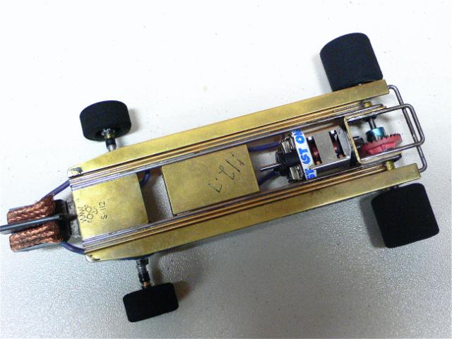
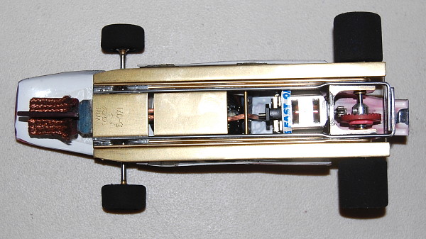
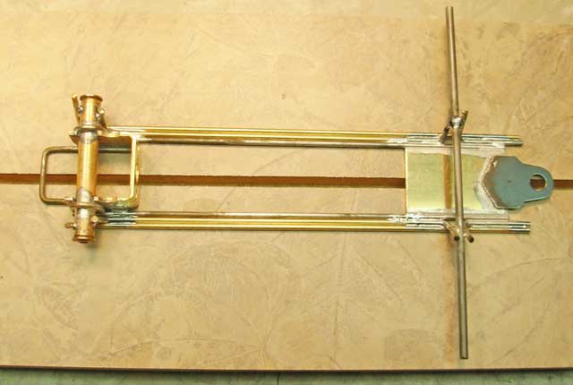
4" wheelbase, 1" guide lead from the front axle.
3/4" wide JK bracket, then three rails each side, one of .062" steel, 2 of .062" brass or low-fuming bronze brazing rod.
The nose piece - .062 thick by 1" to 1.25" long, then another loose shaker plate behind it that's about 1.5" long.
Side plates - .062 thick by 1/4" wide and 5" long so they go from the front of the nosepiece all the way to the back of the motor bracket. Connect the side plates to the center shaker plate with your pin tubes, then use some little wire saddles like the pan stops on a CanAm frame to hold the whole lot in place and let it "rattle about .010 to .015 up and down and about .030" or so fore and aft.
Ask Jay Kisling how this one works.......
Grand Champion Poster

Posted 09 April 2009 - 06:46 PM
I think .062 thick by 1" to 1.25" long threw you off a bit.How are you using the 1" wide nose plate with a 3/4" motor box? Are you shimming the sides of the motor box or something to make it the same width as the nose pc when you run the rails from front to back?
Mike Swiss
Inventor of the Low CG guide flag 4/20/18
IRRA® Components Committee Chairman
Five-time USRA National Champion (two G7, one G27, two G7 Senior)
Two-time G7 World Champion (1988, 1990), eight G7 main appearances
Eight-time G7 King track single lap world record holder
17B West Ogden Ave., Westmont, IL 60559, (708) 203-8003, mikeswiss86@hotmail.com (also my PayPal address)
Note: Send all USPS packages and mail to: 692 Citadel Drive, Westmont, Illinois 60559
On The Lead Lap
Posted 09 April 2009 - 08:09 PM
I think .062 thick by 1" to 1.25" long threw you off a bit.
It's not 1" x 1.25".
Dennis can confirm but I'm 99.9% sure the plate in the pic is 3/4" wide.
Village Luddite
Posted 09 April 2009 - 09:02 PM
I am not a doctor, but I played one as a child with the girl next door.
Posting Leader
Posted 10 April 2009 - 12:06 PM
Village Luddite
Posted 10 April 2009 - 08:45 PM
I am not a doctor, but I played one as a child with the girl next door.
Village Luddite
Posted 14 April 2009 - 08:48 PM
I am not a doctor, but I played one as a child with the girl next door.
Posting Leader
Posted 15 April 2009 - 07:24 AM


