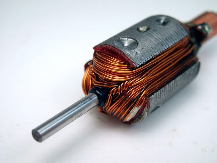
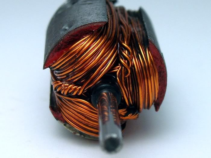
Okie Dokie, I'll put the motor on hold for now as I've done some solder'n

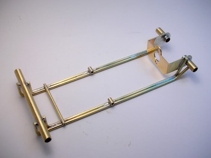
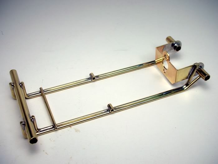
. With the 4 main rails bent to shape, trued up and the ends left long everything just fell together in the jig:
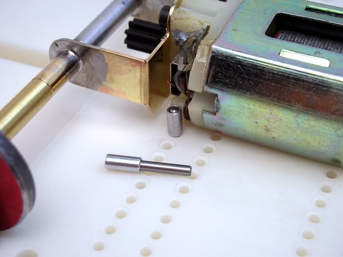
There are pins to line everything up nice and square:
Pins align the front body mount/drop arm up stop:
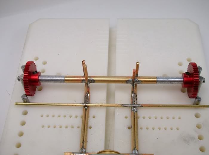
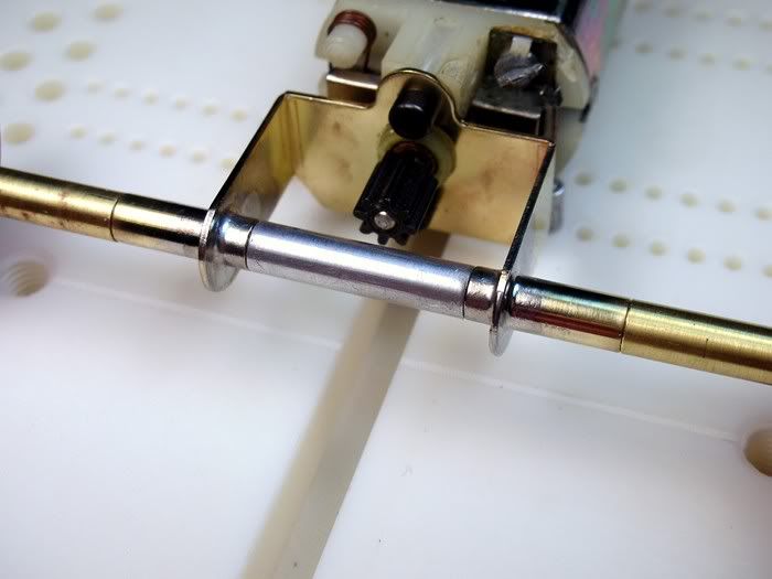
More pins align the drop arm pivot tubes:
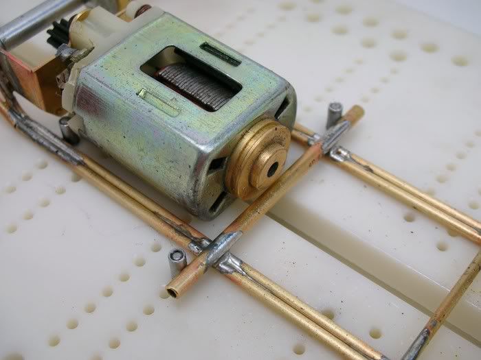
OOPS!

what a mess

"life's messy, clean it up"

:
When this happens to you just suck the crap-O-la out of there

:
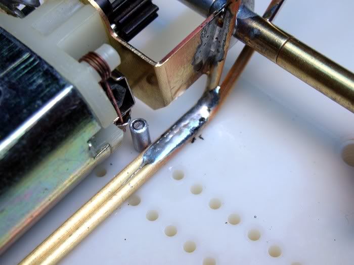
All better now :
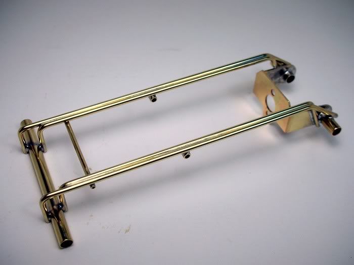
Out of the jig and ready to be trimmed up. The long ends on the main rails help me make sure they lined up vertically. It does look goofy though

:
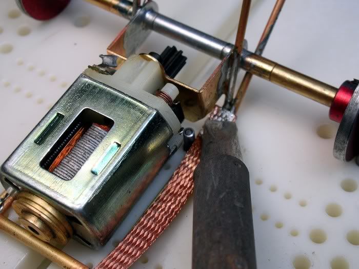
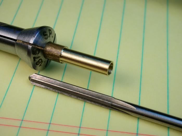
I find it easier to use one long piece of tube for the drop arm pivot and cut the center out. Sometimes there is stress built up and when the tube is cut it will grab and break the cut off wheel. You can first cut the tube in half and gently move the wheel side to side as you cut. This widens the kerf so the wheel won’t break:
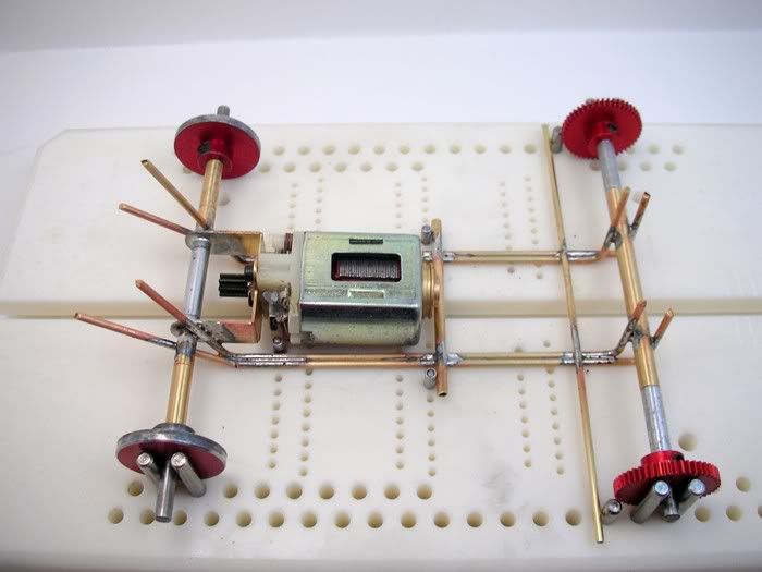
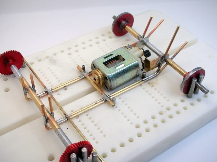
All 12 pounds of excess brass is trimmed off and the K&S Metals Company should be very happy with my technique
:
All the solder on top of the rails where the iron touched will be sanded off with 320 and then 600 grit sandpaper. This is completely unnecessary but I like the way it looks to have as much of the brass exposed as possible. I'll also chamfer the ends of all the rods and tubes where they were cut off. This usually takes me longer to do than the actual building.
But, when I'm done, you can run your hand over the chassis and not feel any shape edges. Just like my old German Journeyman Machinist teacher taught me........thanks Otto!
"Get to the burr bench apprentice!"
"OK Otto."
Onward.............


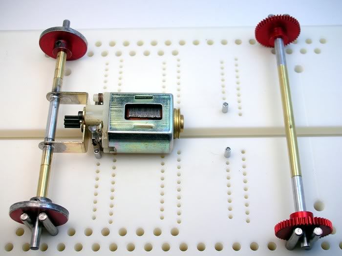
 . It's my new Rick's chassis jig
  :
: