Jump to content


Photo

Z-rail chassis theory


  • Please log in to reply
69 replies to this topic

#1 Lucky Me

Lucky Me

    Rick Maynard

  • Full Member
  • PipPipPipPip
  • 481 posts
  • Joined: 21-October 08
  • Gender:Male
  • Location:Columbus, OH

Posted 13 May 2012 - 03:49 PM

I know there have been several conversation's, topic's, build's, ect....

Since I destroyed my best F1 @ the Columbus F1 500 @ Tom Thumb Hobby's I have started a new
F1 build and thought I would try my hand at a "Z" rail design, I have never built this style of chassis so
I was hoping to get some opinion's, theory, ect.. on a couple thing's from some of the builder's/racer's that have built some of these as well as raced them.

This car will primarily be ran on a King track.

1.What do you like about this design and why ?
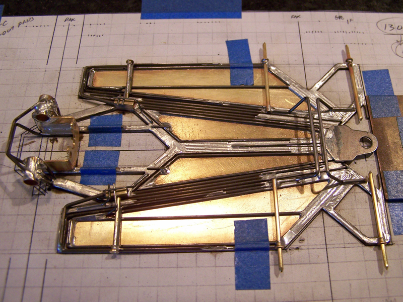
2.Any lesson's learned from the 1st one you built to the next ?

All opinion's welcomed

:)
Rick Maynard
Build it, Race it, Break it, Fix it !

Don't Outsmart Common Sense !


#2 MantaRay

MantaRay

    a dearly-missed departed member

  • Member at Peace
  • PipPipPipPipPipPipPip
  • 2,859 posts
  • Joined: 05-March 06
  • Gender:Male
  • Location:Chicagoland

Posted 13 May 2012 - 04:33 PM

I'll get some pics posted later...but...the original Mike Swiss build.........had the center 3/4" weight held to the nose piece with 2 wires.....pans were then attached with wire to the center piece.........Rick Davis has some similiar attachments..........
Works well...........but heavy............little movement...............
A later build of mine has shaker pans.............The z-rail part is relatively simple..........pan attachment is a bit more difficult....BTW the pan need to be narrowed from .250...........to fit
DSC04220.JPG
DSC04219.JPG
Ray Price
11/4/49-1/23/15
Requiescat in Pace

#3 Lucky Me

Lucky Me

    Rick Maynard

  • Full Member
  • PipPipPipPip
  • 481 posts
  • Joined: 21-October 08
  • Gender:Male
  • Location:Columbus, OH

Posted 13 May 2012 - 04:40 PM

Thank's Ray,

I have the pan's figured out, I'm using a metric strip that measure's .236 wide and .040" thick

I am also using an FSF MB that is 1.300 wide. Will start posting pic's later on in the build.

Rail's are .063, and nose piece is 3/4 wide. Made a plate to surround the MB also out of .050
Rick Maynard
Build it, Race it, Break it, Fix it !

Don't Outsmart Common Sense !

#4 MantaRay

MantaRay

    a dearly-missed departed member

  • Member at Peace
  • PipPipPipPipPipPipPip
  • 2,859 posts
  • Joined: 05-March 06
  • Gender:Male
  • Location:Chicagoland

Posted 13 May 2012 - 04:49 PM

Rick........I'm sure your build will be a beauty and fast
Ray Price
11/4/49-1/23/15
Requiescat in Pace

#5 MantaRay

MantaRay

    a dearly-missed departed member

  • Member at Peace
  • PipPipPipPipPipPipPip
  • 2,859 posts
  • Joined: 05-March 06
  • Gender:Male
  • Location:Chicagoland

Posted 13 May 2012 - 05:08 PM

BTW..........the nose piece is actually a JK Can Am plate that was cut up to make what you see.........
Ray Price
11/4/49-1/23/15
Requiescat in Pace

#6 Lucky Me

Lucky Me

    Rick Maynard

  • Full Member
  • PipPipPipPip
  • 481 posts
  • Joined: 21-October 08
  • Gender:Male
  • Location:Columbus, OH

Posted 14 May 2012 - 11:23 AM

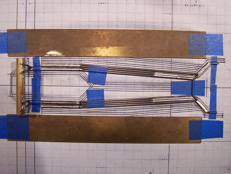
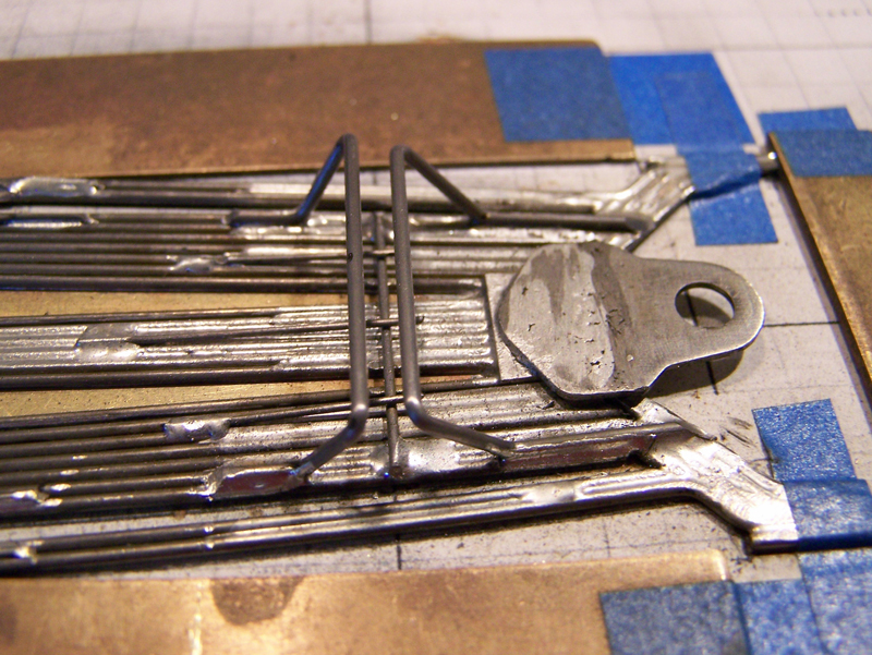
ZR7.JPG


ZR6.JPG


ZR5.JPG


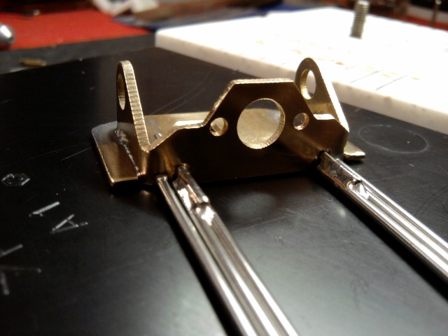
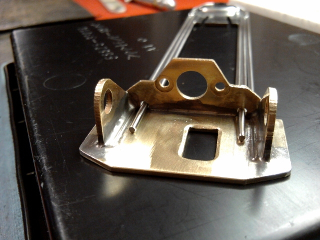
O.K., well, here is what I have so far, I guess the pan's are what is going to hold the main rail's from spreading apart at the frt ?

Will be working on the pan's tonight.
Rick Maynard
Build it, Race it, Break it, Fix it !

Don't Outsmart Common Sense !

#7 Phil Irvin

Phil Irvin

    Checkered Flag in Hand

  • Full Member
  • PipPipPipPipPipPip
  • 1,764 posts
  • Joined: 21-July 08
  • Gender:Male
  • Location:Wesley Chapel, FL

Posted 14 May 2012 - 11:38 AM

LOOKIN GOOD.... I like the way you have done the stops. Go FOR IT.....

OLPHRT
PHIL I

#8 Phil Smith

Phil Smith

    Posting Leader

  • Member at Peace
  • PipPipPipPipPipPipPip
  • 3,582 posts
  • Joined: 03-November 07
  • Gender:Male
  • Location:Irving, TX

Posted 14 May 2012 - 01:03 PM

Very nice work! :good:
Phil Smith
???-2/31/23
Requiescat in Pace

#9 911GT3

911GT3

    Race Leader

  • Full Member
  • PipPipPipPipPip
  • 744 posts
  • Joined: 17-November 07
  • Gender:Male
  • Location:Hilliard, OH

Posted 14 May 2012 - 05:07 PM

Looks good, Rick.

Eric Balicki


#10 Rick Moore

Rick Moore

    CMF3

  • Full Member
  • PipPipPipPipPip
  • 500 posts
  • Joined: 22-November 09
  • Gender:Male
  • Location:Tampa

Posted 14 May 2012 - 05:27 PM

Rick

Some good questions you have there. As for what I like about an indirect main rail system (“Z-Rail” as commonly called here…) is that it creates a greater amount of inherent flex to a chassis that can be lessened through the use of other controlling structures as desired. (The opposite, a direct main rail system does not allow greater flex to be added.) And as for what I have learned about the successive designs, not much for my part, as all the designs/builds I have made have used the same design and materials (all of mine are 0.047” wire framed chassis) as I incorporated other design elements onto this type of main rails. Others might better be able to chime in here with their observations on various layouts and wires used. The one thing I have found is there is no difference between medial-to-lateral versus lateral-to-medial layout of the rails (other than which fits the desired design better).

As for what will “…hold the main rail's from spreading apart…”, I use one or both of two design elements. One, I always incorporate a front “spreader” wire that holds the front wing assemblies together (due to the fact all the designs have had separate center-guide assemblies). The second, on some designs the use of spanning front axle uprights on the laterally adjacent rails (ie, your side pans as you said) accomplish the same result.

Here are two pics, a CanAm and F1, showing the main rails (with the front spreader):

1309-C build 06.jpg

A306 build 04.jpg

And the same chassis with the spanning front axle uprights:
1309-C build 31.jpg

A306 build 21.jpg

Hope this gives you some food for thought.

CMF3 (Rick)

#11 Lucky Me

Lucky Me

    Rick Maynard

  • Full Member
  • PipPipPipPip
  • 481 posts
  • Joined: 21-October 08
  • Gender:Male
  • Location:Columbus, OH

Posted 14 May 2012 - 06:22 PM

Rick..........

Thank you for some insight and the pic's to digest with your concept's.

Your build's are very "busy" to say the least. but are also cool as hell !

Can you possibly elaborate on what type of "loading" you feel take's place on the race track with both the Can Am and F1 you have posted, what I mean is how do you feel forward bite on accelleration, through flat and banked turn's is gained/lost ? Do you feel with all the movement that it eat's up some H.P. ? I have witnessed more basic design's of this type be very successful on the track.

I really no nothing about the overall dynamic's of this design, as I said it is my 1st attempt at this design, and it happen's to be an F1. My experience on the "King" has pushed me to build car's (Can Am and f1) with very little movement with different pan design's whether it be a shaker, floppy, plumber ect...

Anyway's I appreciate the dialogue you have posted, and look forward to moore !

Thank you.

R.M.
Rick Maynard
Build it, Race it, Break it, Fix it !

Don't Outsmart Common Sense !

#12 Phil Irvin

Phil Irvin

    Checkered Flag in Hand

  • Full Member
  • PipPipPipPipPipPip
  • 1,764 posts
  • Joined: 21-July 08
  • Gender:Male
  • Location:Wesley Chapel, FL

Posted 14 May 2012 - 10:46 PM

RICK,

Glad to see ya on again. I know the learnin stuff is a killer and takes up most of your time. Are you goin to be able to take some time off this summer for some fun? Me....I'm slowin down some. Ain't got the 'gotta go racinitice' as bad as I usta :heat: BUT is still around. See ya soon,.... :shok:

OLPHRT :sarcastic_hand:
PHIL I.

#13 Chris Barnes

Chris Barnes

    Race Leader

  • Full Member
  • PipPipPipPipPip
  • 556 posts
  • Joined: 06-May 08
  • Gender:Male
  • Location:Atlanta, GA

Posted 15 May 2012 - 07:41 AM

Is the original Z-rail theory to simulate Eurosport cars? That is what I see (sort of) as there is a lot of movement in the twisting flex direction, but a lot of stiffness up and down (like going through the bank). I don't know the correct terms to use on this - I am from the EE background and not the ME background.

#14 Noose

Noose

    Grand Champion Poster

  • IRRA National Director
  • PipPipPipPipPipPipPipPip
  • 23,298 posts
  • Joined: 08-November 06
  • Gender:Male
  • Location:Denville, NJ

Posted 15 May 2012 - 08:10 AM

The downside sometimes to the Z-Rail concept on sports car frames is the flex down the straight and through a bank. Why I, and some others, have seen is the frames works stupid good from the deadman to the lead on on a King but seems to go soft down the main straight and through the bank. This was partially corrected through some testing where additional points on the rails (2 in front and 2 in the rear) were "tacK' soldered to add some stiffness back in.

Have not tried a F1 built in this manner so I can't say whether the same thing happens.

Joe "Noose" Neumeister
Sometimes known as a serial despoiler of the clear purity of virgin Lexan bodies. Lexan is my canvas!
Noose Custom Painting - Since 1967
Chairman - IRRA® Body Committee - Roving IRRA® Tech Dude - "EVIL BUCKS Painter"
"Team Evil Bucks" Racer - 2016 Caribbean Retro Overall Champion
The only thing bad about Retro is admitting that you remember doing it originally.


#15 Lucky Me

Lucky Me

    Rick Maynard

  • Full Member
  • PipPipPipPip
  • 481 posts
  • Joined: 21-October 08
  • Gender:Male
  • Location:Columbus, OH

Posted 20 May 2012 - 09:39 AM

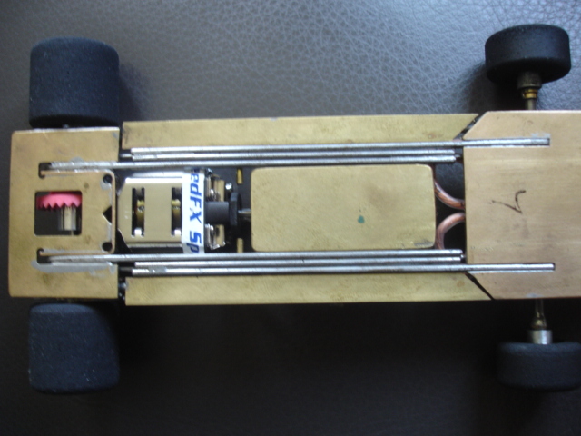
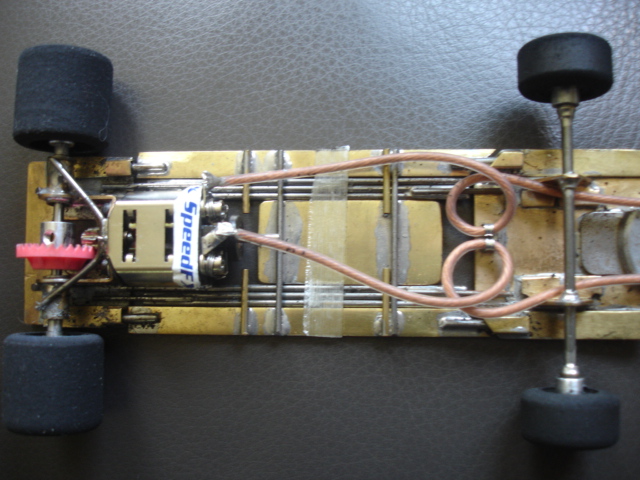
IMG_20120519_233202.jpg


IMG_20120519_233257.jpg


IMG_20120519_233448.jpg


IMG_20120520_094608.jpg


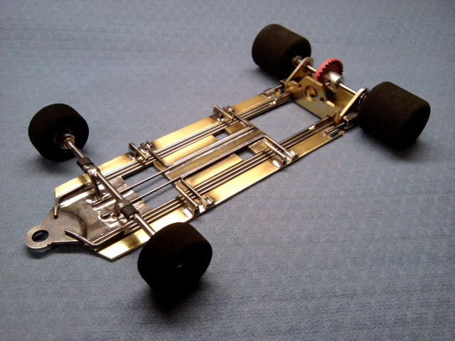
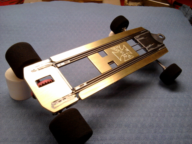
Finished this up last night.

Now that I have had a chance to hold a working "Z" Rail chassis in my hand to observe the type of movement this design has, I will say it has a unique suspension integrated to this particular type of design.

Remind's me of my Off Road R/C day's when I would set up my shock's and have the car/truck setting flat on a surface and go around and lift each wheel off the ground to ensure each tire/wheel had the same amount of travel before the 2nd wheel would come off the ground. This is what this design does. I can have the chassis on the tech block and each wheel can be lifted without any of the other 3 wheel's lifting around all 4 corner's of the frame untill the frame hit's it's stop's. I hope this is how it is suppose to be, if not, I screwed up somewhere.

Frame still has a verticle stiffness to it that feel's more traditional if the rail's were all soldered solid, but the twist is unreal. may have to adjust some of that out of it. The track will tell.

This particular build weighed in at 107 g's Race ready, no lead.

Next up is TESTING ! can't wait.
Rick Maynard
Build it, Race it, Break it, Fix it !

Don't Outsmart Common Sense !

#16 John Miller

John Miller

    This space for rent

  • Full Member
  • PipPipPipPipPipPip
  • 1,150 posts
  • Joined: 12-November 07
  • Gender:Male
  • Location:Hartford, MI

Posted 20 May 2012 - 09:48 AM

Nice build Rick.

"Racing makes heroin addiction look like a vague wish for something salty" - Peter Egan

ProSlot.png


#17 MSwiss

MSwiss

    Grand Champion Poster

  • IRRA National Director
  • PipPipPipPipPipPipPipPip
  • 25,904 posts
  • Joined: 16-April 06
  • Gender:Male

Posted 20 May 2012 - 11:09 AM

Rick.
Terrific job on the build.

Good idea going with .040 brass to keep the weight down.

My F1 Z-rail builds use .062 and they are always a bit on the heavy side without much of a way to lighten them.

It will be interesting to see what someone with lots of Tom Thumb experience can get out of it, especially with being able to test and tune it
at your leisure.

One thing I'll add is that the front axle just being supported by struts coming out of the slots in the nose pc. hasn't worked out that well.
Even with carefully cleaning out the "recast" in those slots, I think they are in a bit too far, inboard, and might get pulled out in a bad crash.
I would add additional ones as far wide out, as possible, probably at the joint where the main rail attaches to nose pc.

Mike Swiss
 
Inventor of the Low CG guide flag 4/20/18
IRRA® Components Committee Chairman
Five-time USRA National Champion (two G7, one G27, two G7 Senior)
Two-time G7 World Champion (1988, 1990), eight G7 main appearances
Eight-time G7 King track single lap world record holder

17B West Ogden Ave., Westmont, IL 60559, (708) 203-8003, mikeswiss86@hotmail.com (also my PayPal address)

Note: Send all USPS packages and mail to: 692 Citadel Drive, Westmont, Illinois 60559


#18 ejgehrken

ejgehrken

    On The Lead Lap

  • Full Member
  • PipPipPipPip
  • 345 posts
  • Joined: 07-May 12
  • Gender:Male
  • Location:Southington, CT

Posted 23 August 2012 - 06:53 PM

After reading these posts, I'm still having trouble grasping what makes a chassis a Z-Rail.
Can someone explain what a Z-Rail is and what theories govern its performance characteristics?
Eric Gehrken
Gehrken Retro Chassis
2015-16 Retro East Overall Champion
2015-16 Retro East Constructor's Champion
2013-14 New England Retro Racing Overall Champion

#19 MSwiss

MSwiss

    Grand Champion Poster

  • IRRA National Director
  • PipPipPipPipPipPipPipPip
  • 25,904 posts
  • Joined: 16-April 06
  • Gender:Male

Posted 23 August 2012 - 07:06 PM

The rails are not all soldered together.

They are connected back and forth in short of a flat "Z" shape.

In the theory to make three rails into one long one.

Another good example of a "Z" rail is at the below link:

http://slotblog.net/...efit-sano-dave/

Mike Swiss
 
Inventor of the Low CG guide flag 4/20/18
IRRA® Components Committee Chairman
Five-time USRA National Champion (two G7, one G27, two G7 Senior)
Two-time G7 World Champion (1988, 1990), eight G7 main appearances
Eight-time G7 King track single lap world record holder

17B West Ogden Ave., Westmont, IL 60559, (708) 203-8003, mikeswiss86@hotmail.com (also my PayPal address)

Note: Send all USPS packages and mail to: 692 Citadel Drive, Westmont, Illinois 60559


#20 Rick Moore

Rick Moore

    CMF3

  • Full Member
  • PipPipPipPipPip
  • 500 posts
  • Joined: 22-November 09
  • Gender:Male
  • Location:Tampa

Posted 24 August 2012 - 04:42 PM

Can someone explain what a Z-Rail is and what theories govern its performance characteristics?

As Mike says, what you have is a 3-element (three wires in this case) main rail. There is:
1) A wire running forward from and only attached at its rear to the motor box / rear axle assembly;
2) A wire running rearward from and only attached at its front to the front wing assembly (which may include the front axle and guide tongue);
3) A wire in between and connecting the other two wires, attached to the front of the wire from the motor box, and attached to the rear of the wire running from the front wings.

When I first started building chassis with “z-rails” I was working under the “theory” (translation: “Gee, I wonder what happens if…”) of trying to isolate forces working on the front wings (and/or front wheels) of the chassis and minimize those forces from transferring to the motor box / rear axle assembly. Please note, in my own series of builds the guide tongue was already mounted to a separate assembly running directly to the motor box, and not attached to the front wing / front axle assembly (sort of a no-hinge/torsional iso-fulcrum drop arm, without the “drop”); others will be better suited to describing the effects with the guide tongue as a part of the front wing assembly, as I have not built any in that manner. So for the chassis I’ve built the "theoretical triangle” formed between the guide and the rear tires (which includes the motor box / bracket) remains more stable relative to the flex or twist of the rest of the chassis under running forces. This can be a “good-er” thing or a “bad-er” thing, because the amount of tension between the components will affect the chassis handling characteristics in relation to the type of track and track conditions (as well as the other usual car tuning variables). My own experience is that this inter-component tension can be controlled (and even made adjustable) through the use of “spring wires” between various chassis components.

Well, hopefully that wasn’t too confusing…

Rixk

#21 Tex

Tex

    Grand Champion Poster

  • Full Member
  • PipPipPipPipPipPipPipPip
  • 9,243 posts
  • Joined: 07-July 06
  • Gender:Male
  • Location:Denton, TX

Posted 24 August 2012 - 06:58 PM

The bottom view of Rick's chassis says it all. LOOK CLOSELY at the 3 rails on each side and PAY ATTENTION to how they are soldered together. The inside rail and the middle rail are soldered together at the rear. Similarly, the outside rail and the middle rail are soldered together at the front. If you can visually grasp that concept, you have the PHYSICAL makeup of a Z-rail. That's as deep as my mind can go. For the performance characteristics, refer to Rick Moore's words above; I trust him.
Richard L. Hofer

Remember, two wrongs don't make a right... but three lefts do! Only you're a block over and a block behind.

#22 SlowBeas

SlowBeas

    Troublesome De-slotter

  • Subscriber
  • PipPipPipPipPipPip
  • 1,010 posts
  • Joined: 15-January 07
  • Gender:Male
  • Location:Lost in South Carolina, USA

Posted 27 August 2012 - 11:27 AM

I've noticed that some z-rails connect to the motor bracket from the outside of the rail configuration, while others connect on the inside. What difference does it make?
Jim Beasley
South Carolina, USA

"Assuming either the Left Wing or the Right Wing gained control of the country, it would probably fly around in circles."
- Pat Paulsen, 1968
"I drive way too fast to worry about cholesterol."
- Steven Wright ca. 1983

#23 Guy Spaulding

Guy Spaulding

    Unintentional Instigator

  • Full Member
  • PipPipPipPipPipPip
  • 1,922 posts
  • Joined: 06-November 09
  • Gender:Male
  • Location:High Point, NC

Posted 27 August 2012 - 11:48 AM

If I understand it correctly the use of Z rails will promote side-to-site (twisting) flex, while minimizing forward-aft flex. This allows more equal downforce distribution while maintaining longitudinal rigidity

#24 SlowBeas

SlowBeas

    Troublesome De-slotter

  • Subscriber
  • PipPipPipPipPipPip
  • 1,010 posts
  • Joined: 15-January 07
  • Gender:Male
  • Location:Lost in South Carolina, USA

Posted 27 August 2012 - 06:26 PM

Sorry, I probably didn't state my question properly...

Sometimes, the rail that connects the motor bracket connects from the outermost position, with the other two rails connecting to the inside of that first rail connected to the motor bracket. The one connecting the fore piece will be connected by the third rail, which is innermost of the three. (post #15)

Then on others z-rails, the rail connecting the motor bracket is the innermost of the three --- with the other two rails moving to the outside of the one connected to the motor bracket. (post #2)

I'm just wondering if one method is better than another, or is it six of one/half dozen of the other?

Does the question make better sense this time? (You'd never know I write for a living, would you?)
Jim Beasley
South Carolina, USA

"Assuming either the Left Wing or the Right Wing gained control of the country, it would probably fly around in circles."
- Pat Paulsen, 1968
"I drive way too fast to worry about cholesterol."
- Steven Wright ca. 1983

#25 Tex

Tex

    Grand Champion Poster

  • Full Member
  • PipPipPipPipPipPipPipPip
  • 9,243 posts
  • Joined: 07-July 06
  • Gender:Male
  • Location:Denton, TX

Posted 27 August 2012 - 06:31 PM

Question understood. Don't know the answer.
Richard L. Hofer

Remember, two wrongs don't make a right... but three lefts do! Only you're a block over and a block behind.


Electric Dreams Online Shop