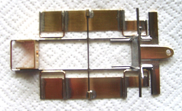
At the suggestion of a Slotblog member, this thread is being created so the many talented Retro chassis builders here can have a place to showcase and to explain the design principles underlying their scratchbuilt chassis. The idea behind this gallery thread (and its posting restriction) is to create one place where Retro chassis designs can be seen, compared, and contrasted.
All questions and discussion related to any chassis showcased here are to be posted to the other pinned thread in this forum: Chassis Gallery Discussion.
Please note that posts to this thread are to be made ONLY by the builders of the chassis being shown.
Posts that do not comply with this restriction will be moved to the Discussion thread without notification.
One more point: the hope is that this gallery will become a reference for scratchbuilt Retro racing chassis designs. It is not meant to be a catch-all for all types of scratchbuilt chassis nor was it created to replace the other venues on Slotblog where scratchbuilt chassis are shown and discussed, i.e. the Scratchbuilt forum, the Pro Racing Cars & Replicas forum, etc.
Now, who is going to make the first post showcasing their chassis?

Scratchbuilt chassis gallery
#1

Posted 16 April 2008 - 12:18 PM
- Birdseed likes this
Gregory Wells
Never forget that first place goes to the racer with the MOST laps, not the racer with the FASTEST lap
#2

#3

Posted 16 April 2008 - 11:05 PM
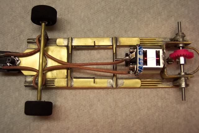
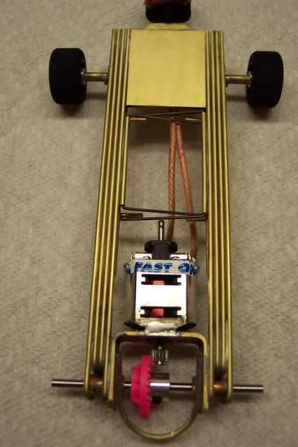
Mostly all brass construction using .062" brass rod, .064" center, and .032" pans. R-Geo motor bracket. The pans are hinged on the opposite sides for better pan movement. 4" wheelbase with a 5" guide lead.
#5

Posted 17 April 2008 - 11:17 AM
The whole idea with this chassis was to use the Warmack kit as a starting point. I wanted to remove as much weight as I could (from places where I feel it doesn't do much good), not so much to lighten the car, but to allow me to place weight where it would do more good, handling-wise.

I removed a lot of material from the basic Warmack pan (using a nibbler for much of it and a Dremel and files for the rest): from the inner edges of the pans, the front wings, the front axle uprights, the guide tongue, and from the center "tongue" of the nosepiece. The middle body mount tabs on the pans were hammered flat and then trimmed off. IIRC the unmodified pan weighed 41.15 grams and once I was done chopping on it, it weighed 28.85 grams or thereabouts.

What I wanted to do with the pan hinge mods was to push the hinges forward and aft to give more flexibility to the main rails. The front hinge tubes (3/32" square tubing) were pushed well up into the nosepiece and the rear hinge tubes (3/32" round tubing) were pushed back under the motor bracket. Additionally, I wanted to get the hinge arms off the tops of the pans, thus they are soldered to the edges. Hinge pin material is .055' piano wire. The wetted surface of the front hinge to pan joints seemed a little small, so the additional .032" braces were added for more strength.
The motor bracket was spread into a V for two purposes: to move the motor closer to the rear axle and to give a wider bushing "stance" without having to add tubing chunks for mounts. Additionally, the spread bracket allowed soldering the bottoms of its "arms" onto the main rails, helping to stiffen the bracket assembly and giving a better attachment of the bracket to the main rails. This worked really well...
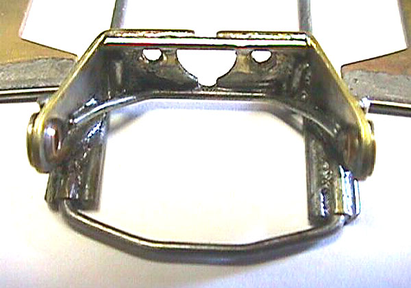
Here's my possibly-excessive bracket bracing. My feeling is that many builders don't realize the magnitude of the forces generated at the gear interface. I don't think it is possible to make a motor cage assembly too strong, but it sure is possible to make one too weak! The straight upper brace on the motor bracket is 1/16" tubing; everything else is piano wire.

Here you can see the sloppy results of building in a hurry: the lefthand rail in this pic is about 1/16" longer than the righthand rail, and I'll fix this when I revise the chassis. Note how the gear guard plugs into the rear of the pan hinge tubes.
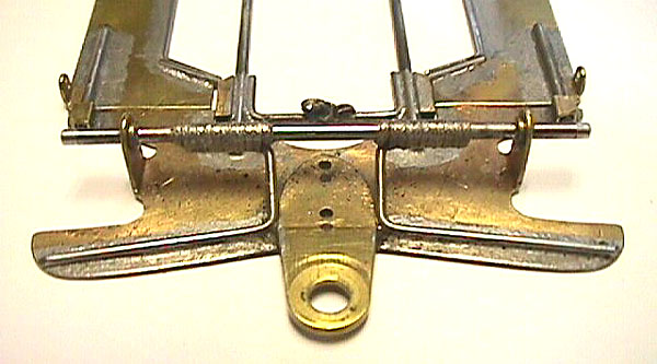
A different front axle mounting arrangement, what I call a torsion bar set-up. The .032" brass pan material is simply not strong enough for front wings (at least on my cars, where wall contact is a fairly frequent occurrence!) and the .055" piano wire is run along the top of the front wings to stiffen them. I wanted to revise the stock Warmack front axle mounting arrangement, as I felt there was too much material in the front uprights to suit me. Note that the front axle is not soldered to the uprights; the 3/32" collars soldered to the axle actually spigot into the upright holes, which are now small slots. I finished this chassis at the R4 and didn't have any decent copper tie-wire in my box, so I used some braided silver shunt wire I did have. I figured if I hadn't used the stuff for brush shunts in the last 20 years, I might as well use it here.
After racing this chassis a few times, I have decided I went too far and made the chassis too flexible, because it has so much bite I can't get it to slide as much as I want it to, even with hard tires. So I will be making some mods to stiffen it up a bit.
The plan is to lengthen the rear pan hinge tubes and to solder the rear pan hinge arms to the angled cut-outs as with the front hinges. I'll also add .032" joint braces to the rear hinge to pan joints, as with the front ones, and will extend them touch the front .032" braces to stiffen the pans themselves a bit. I may also lengthen the L-shaped bracket braces that tie the corners of the bracket to the main rails so that the horizontal legs of the braces extend farther forward alongside the motor. In the front, I will reverse the U-shaped brace (that carries the ear-ring back) so that the open side of the U points forward.
In the front, I plan to shorten the joint where the front axle attaches to the torsion bars; with wire-tying, these two joints don't need to be as long and heavy as they are now.
These modifications should add some beam stiffness, as the main rails will have a shorter unsupported length. If the car still has too much bite after these changes, I'll make a longer front U-brace and extend the rear bracket L-braces even more.
BTW, IIRC this chassis ready-to-race weighed roughly 115 grams with a TSR D3 motor and an Eddie Mac-painted Lola body I bought at the Sano. That's with no added lead, though it does usually carry a little when it is raced.
And it dosn't really look as nasty in appearance as the pics seem to suggest. I call it racing quality, not presentation grade like the gorgeous chassis Rick and Steve create.
Now don't forget! If you wanna tell me what a POS this is, do it in the "Discussion" thread, not here.
- Jaak likes this
Gregory Wells
Never forget that first place goes to the racer with the MOST laps, not the racer with the FASTEST lap
#6

Posted 17 April 2008 - 12:06 PM
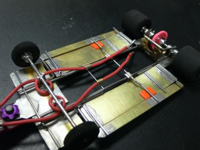
I thought you may be interested in seeing the second version.
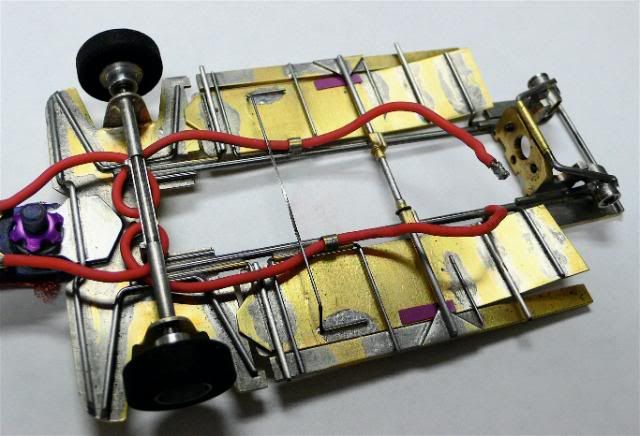
I built this one based on a Warmack kit and used a BWA rear bracket, my favorite. I made this a 4" WB instead of 3.9" and went with an .850" GL instead of .90". Rails are .078" piano wire on both cars. The outer pans on version 2 are 3/16" instead of 1/4" to save weight as well as the rear split pans.
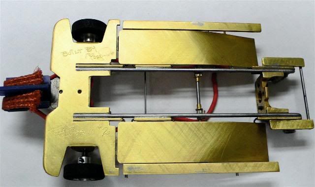
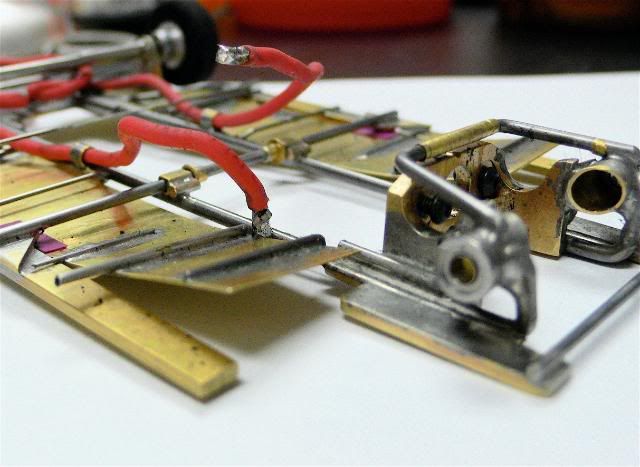
The "aero" pans on both chassis are .016" brass and support the body mounts. The new version has a more pronounced wing profile to the pans.
So far I have run this at Sonny's on the King and it was fast but I went with the original simply because I am used to it. I also tried it at Liquid Lou's 220' track and it ran well there also, just not as smooth as my original.
I ground on the spring between the pans to make it softer and went to a pair of Sonic fronts. I will take it as my race back-up car for the race this weekend. I need to get more laps on it to break everything in...
Both chassis when testing ran the best with the O/S long Ti22.
- Jaak, 7D7 Hobbies and Blondie like this
Anthony 'Tonyp' Przybylowicz
5/28/50-12/20/21
Requiescat in Pace
#7

Posted 23 April 2008 - 09:00 PM
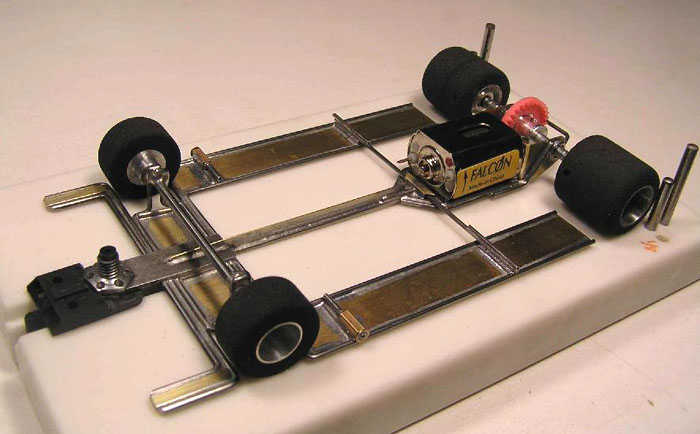
Although I've been scratchbuilding for a long time these are the first inlines I've built in 40 years! I really learned a lot about inline chassis dynamics with these first two and have had to make quite a few mods (motor bracket stiffening and increased chassis torsional stiffness) since these pictures but hopefully these will inspire a few new designs.
I've got a couple of new designs on the drawing board and should have something new to show in about a month. I promise they will be quite a bit different from these!


- Jaak, 7D7 Hobbies, Vlado Yankov and 3 others like this
Jay Guard
IRRA Board of Directors (2022-Present),
Gator Region Retro Racing Director (2021-Present)
SERRA Co-Director (2009-2013)
IRRA BoD advisor (2007-2010)
Team Slick 7 member (1998-2001)
Way too serious Retro racer
#8

Posted 28 April 2008 - 07:32 PM
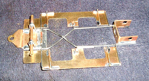
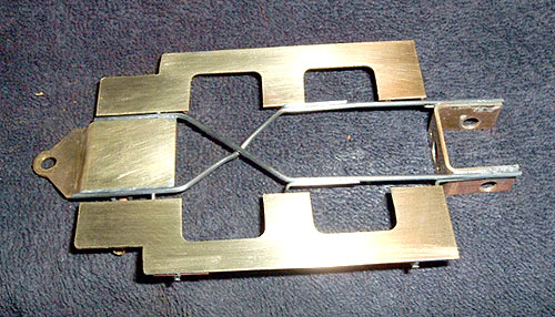
Built with roadcourse in mind, will test at Mac's...
- Jaak and Steve Turner like this
Rick Bennardo
"Professional Tinkerer"
scrgeo@comcast.net
R-Geo Products
LIKE my Facebook page for updates, new releases, and sales: Rgeo Slots...
Lead! The easy equalizer...
#9

Posted 03 May 2008 - 12:33 PM
- Jaak likes this
Rick Bennardo
"Professional Tinkerer"
scrgeo@comcast.net
R-Geo Products
LIKE my Facebook page for updates, new releases, and sales: Rgeo Slots...
Lead! The easy equalizer...
#10

Posted 04 May 2008 - 09:29 AM
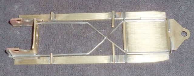
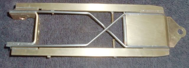
It features:
Three rail main frame: .062" center and .055" outer.
WB 4.00"
GL .935"
.028" steel nose and pans
Weight (as pictured): 57.5 grams


Can't wait to try it out!!
- Jaak and Steve Turner like this
Resurrected slot racer/builder...
Former member of Team LED...
<_____
O_____\_
There's a fine line between racing and standing
at the driver's panel looking like an idiot...
#11

Posted 04 May 2008 - 11:04 AM

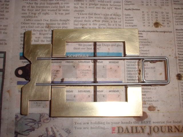
And here's my new jig block:
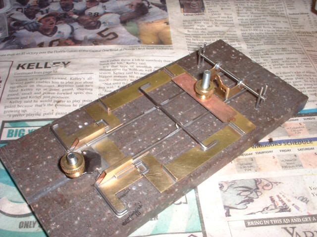
I got the block from eBay for $10.00 with some extra machining at no charge (I added the jig holes). The tech block is made out of Corian and it's the flattest block I've ever bought. Look for "precision-slot-cars" for more of his tech blocks.
- Jaak and glueside like this
First Place Loser in the JK Products
International D3 Builders Competition
#12

Posted 07 May 2008 - 09:44 PM
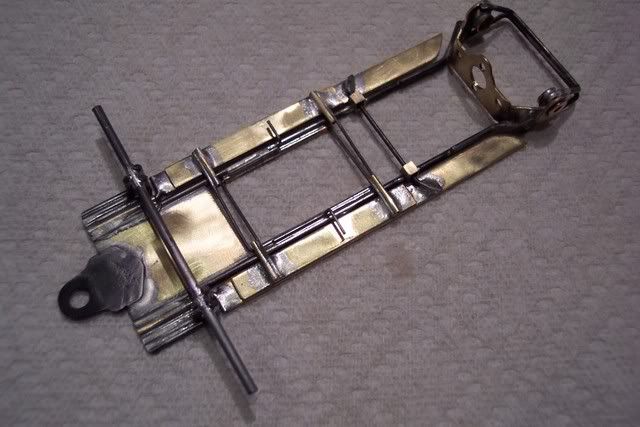
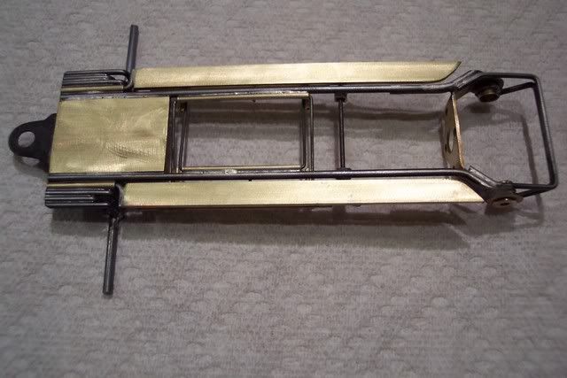
- Jaak likes this
#13

Posted 10 May 2008 - 01:28 PM
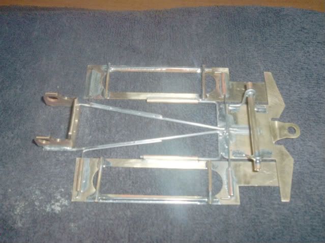
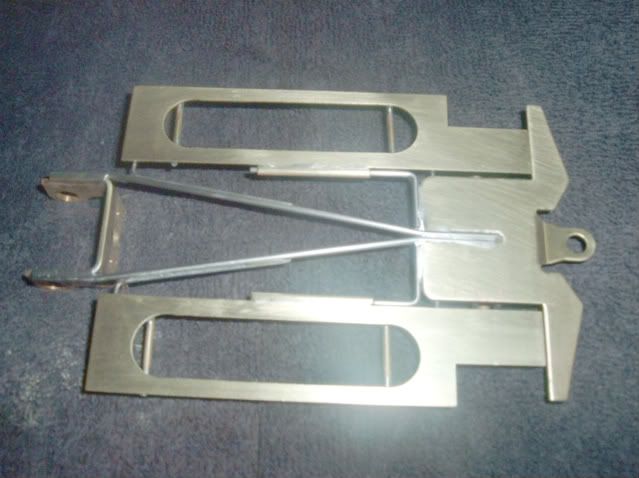
New try. Yeti nose piece, new design hypoid motor box, extra light pans, low profile guide required. If there is anybody that lives close to a track and wants to test it out before next Saturday, give me a PM, I will send right out, and you gotta be going to Mac's for the race too.
Another similar to this coming tomorrow. Same parts... stay tuned.
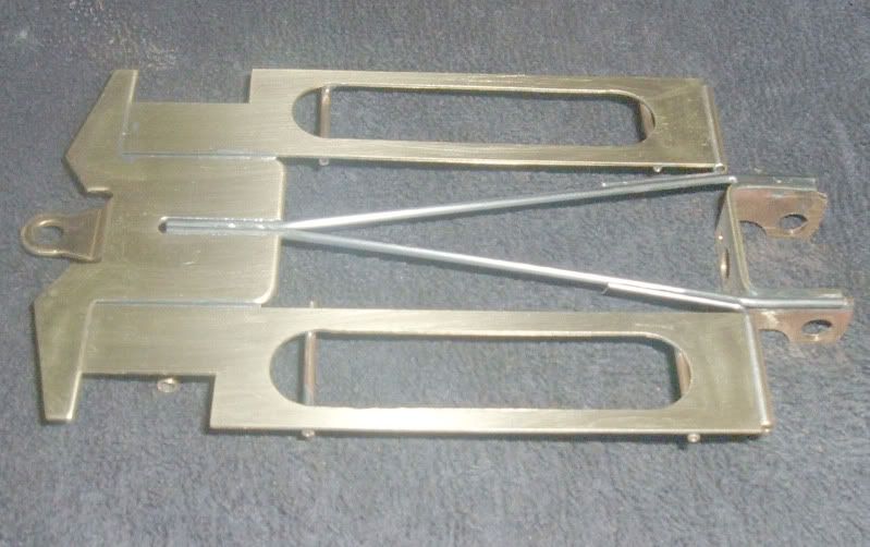
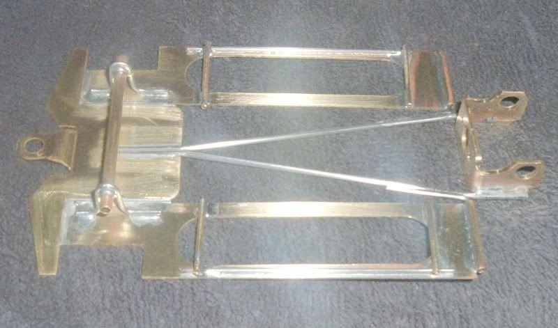
- Jaak likes this
Rick Bennardo
"Professional Tinkerer"
scrgeo@comcast.net
R-Geo Products
LIKE my Facebook page for updates, new releases, and sales: Rgeo Slots...
Lead! The easy equalizer...
#14

Posted 10 May 2008 - 09:28 PM
- Jaak likes this
Rick Bennardo
"Professional Tinkerer"
scrgeo@comcast.net
R-Geo Products
LIKE my Facebook page for updates, new releases, and sales: Rgeo Slots...
Lead! The easy equalizer...
#15

Posted 11 May 2008 - 12:27 PM

- Jaak likes this
First Place Loser in the JK Products
International D3 Builders Competition
#16

Posted 11 May 2008 - 01:32 PM
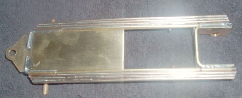
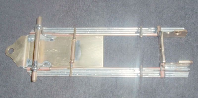
Here is something I have been thinking of for some time. REALLY soft!! 5" X 4-1/8" X 7/8", 49 grams. Mains go thru a tube to probably be just too bitey. Pans are welding rod. Low profile guide tongue.
- Jaak likes this
Rick Bennardo
"Professional Tinkerer"
scrgeo@comcast.net
R-Geo Products
LIKE my Facebook page for updates, new releases, and sales: Rgeo Slots...
Lead! The easy equalizer...
#17

Posted 13 May 2008 - 07:16 AM
I tried something a little different for the pan stops. The gussets should give them more strength without tying the rails together. I tried some 1/4" .032" for body mounts.
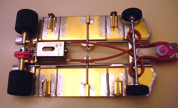
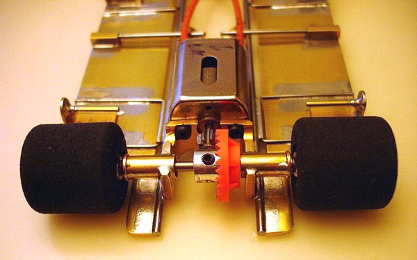


- Jaak, iv_man and Roderick Armstrong Sr like this
11/4/49-1/23/15
Requiescat in Pace
#18

Posted 20 May 2008 - 08:42 PM

This shows the top view of chassis number R4. Some specs:
2 x 0.078" main rails
1" x 1-1/8" 0.062" brass nosepiece
0.032" brass pans
R-Geo motor bracket
Slick 7 guide tongue
Sonic front wheels
Zap earring back
4.062" wheelbase
5.0" guide lead
69.9 grams

This is a close-up of my front end construction, The purpose of having the front hinge tubes so far forward is to provide a plumber effect under braking, i.e. more weight on the nose. I like using square hinge tubing. It provides more surface area on the nosepiece for the solder joint. That, combined with the 0.062" hinge wire, is hopefully strong enough to survive a few wall hits. The square tubing also provides more solder area for the front axle uprights, again, theoretically adding some strength in this critical area. I use a piece of 0.093" wire for the front axle, with independently-rotating front wheels. The front upright/axle joint is reinforced with 0.062" brass rod, bent over the axle and soldered to the uprights.

This is a photo of the rear end assembly. I again used the 0.062" brass rod to reinforce the axle tube/motor bracket area. After attempting to bend a rear brace out of 0.062" wire six times, I finally cut one of my attempts in two, and put it back together with a piece of tubing. Unfortunately, this limits me to a 28 tooth gear, a 29 won't fit! Sucker shouldn't bend, though. At least, not very easily.
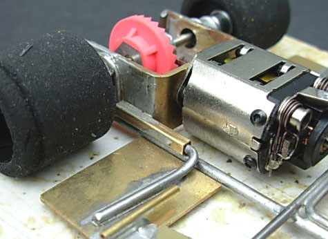
This is a close-up of the rear pan hinge, again using square tubing. This serves as an additional stiffener of the bracket/main rail solder joint. You can also see the chunk of tubing that controls the pan movement. This is 1/8" square with an 0.062" bite bar, with an 0.062" U-brace on the main rails.
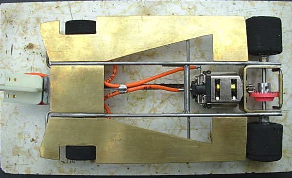
And last, a look at the bottom. I just noticed I haven't numbered this one yet.
I usually design and layout my chassis in Macromedia FreeHand, and then print a couple of copies. One, to check how what I'm building matches what I designed, and the second to cut up to use as a pattern for cutting out the pans.
Mike Patterson
- Jaak, glueside, Eddie Fleming and 1 other like this
I am not a doctor, but I played one as a child with the girl next door.
#19

Posted 21 May 2008 - 12:48 AM
- light weight and aerodynamic.
- light weight rear motor box
- low CG
- stiff flex
- perimeter pan weight
- not fragile
2) The motor box was made very light, but stiff as a rock. I added stiffness with a cross bar soldered across the bottom on the back side of the motor through the bracket connecting to the rails; four .063" rails along the outside; two .063" axle posts completely soldered to the box; .063" rear rail to protect and stiffen up the back of the motor box. The box is stiff and solid, and the strengthing was done low to keep the CG down in the back of the chassis.
3) Everything was designed to have low CG: The motor box as described in 2). Only two front axle posts per side out wide. The motor is set hypoid. Light .047" crossbeam to adjust flex and pan stops. The body pinning was kept low and the side stops were made with .032" steel. Definitely get the rear as low as possible, 50 mil clearance and 15 mil on the front.
4) The King car chassis is very stiff using two .063" steel rails soldered together along the their entire length, with wide rail spacing. The rear and front are very stiff. Note, the four rails of .063" steel in the rear. 4 inch wheel base with 0.9 inch guide.
5) Perimeter pan weight is used for this high-speed car. The pans are as low as possible without dragging.
6) Most of the steel was .063" with longer solder joints. The side pan were .063" thick. The front was near all steel .063" rails. The axle posts were .063". The front bumper was .063", but I'm replacing with .078" steel. The motor box was solidly supported with .063" steel as discribed in 2). The body was reinforced at the pins with body armor and packing tape, but using very small pieces to keep the weight down. The lead wires were lightweight, but not too thin, and definitely soldered to the motor.
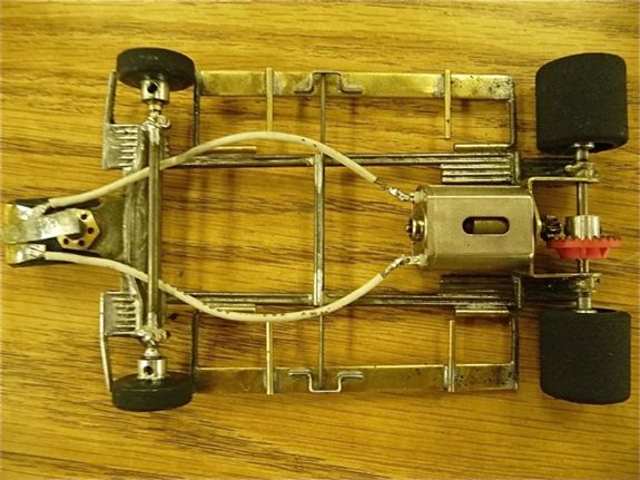

More pics are at Keith Tanaka's SoCal D3 albums in the F1/Can-Am races 4/12/2008 section.
- Jaak and Roderick Armstrong Sr like this
#20

Posted 23 May 2008 - 04:32 PM
All flat brass is .032". Bracket is a RICK hypoid. Guide tongue is a Warmack. Main frame rails are .063" bronze. The two inner frame rails are .062" wire but are not soldered solid. Those rails are free inside of a tube thus providing some longitudinal stiffness and protection for the bronze without adding much torsional stiffness. The inner rails can easily be dropped out completely, or changed for bigger or smaller rails. Those could either be within tubes as shown here or just soldered in solidly. Ideally, this will allow fairly simple trackside flex tuning without a full rebuild.
This version has a 4.650" axle to post length. This is relatively short for me as most of my stuff has been 4.800"-5.000" Running weight without body will be about 114 grams and I expect to add a bit of lead for the BP flat track. This chassis could easily be built down to 105 grams or so.
A little clean-up and off to the tumbler. May hit the track with it tonight or tomorrow.
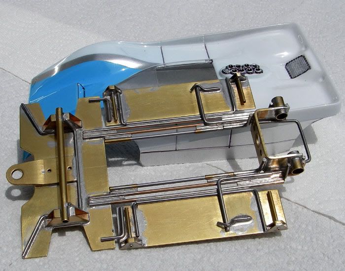
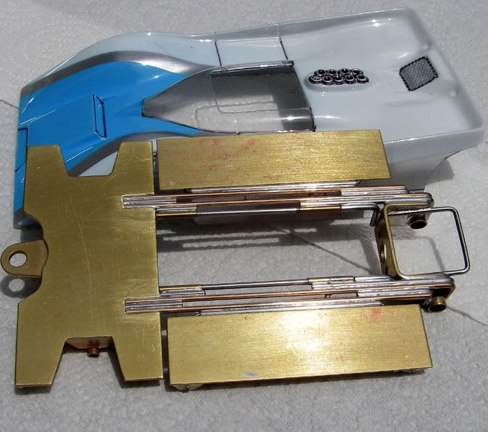
- Jaak and Jimmy La Barba like this
#21

Posted 26 May 2008 - 01:19 PM
Thought it might be worthy to try and duplicate. I built these for Mimis and a Can-Am with the same center section. We shall see???
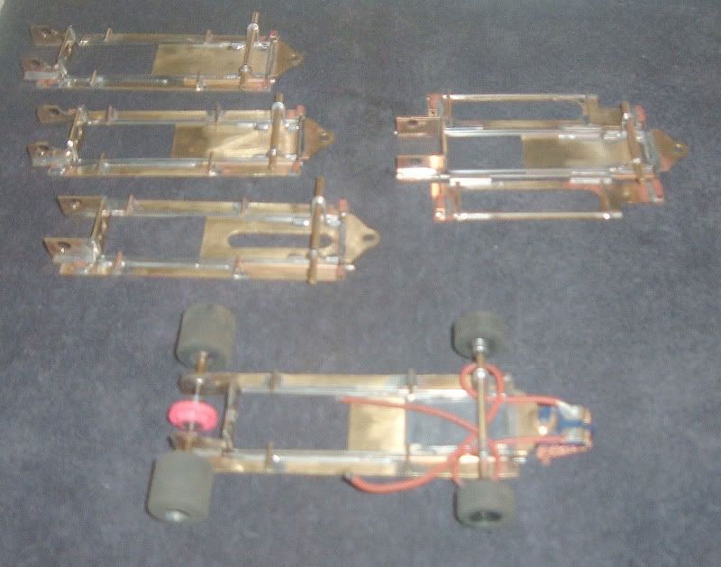
- Jaak likes this
Rick Bennardo
"Professional Tinkerer"
scrgeo@comcast.net
R-Geo Products
LIKE my Facebook page for updates, new releases, and sales: Rgeo Slots...
Lead! The easy equalizer...
#22

Posted 11 June 2008 - 08:05 PM
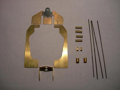
Brass nose and pans are .032, rails are .055", 1/8 "square tubes (four for the floating body mounts and two to limit chassis movement), 1/4" long axle tubs, Slick 7 guide tongue with another piece of .032" brass to raise it up a bit, and finally a WRP motor bracket. The pans are 1" wide and the cuts were made by hand using the all powerful Dremel fiberglass cut-off wheel and then the drum sander (280 grit) to make the curves.

Using one of the best chassis jigs ever made, the four rails were soldered to the nose.
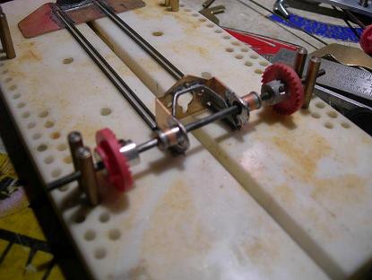
Here the motor bracket is soldered to the rails. I cut a notch out for the inner rails. Then to keep the rails parallel I used two pieces of .025 brass to take up the slight gap between the inner rails and the bracket. This also allowed me to solder the axle tubes in easier as I had to raise the tube slightly. The reason for filling the gap you will see later.

Pans are attached to the rear of the chassis using .055" wire inside tubing to the outside main rails.
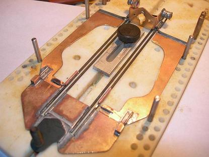
The front pans are attached using the 1/8" brass square tubing and .047" wire inside this tubing. I also used a small piece of .025" brass to raise the wire so wire would sit flat in the tubing. The 1/16" round tubing on the rails has .025" wire running through it and completes the hinged pans. By the way, for those that don't know about the R-Geo jigs, if you use the inner peg holes your retro chassis will be exactly 3-1/8 wide!

The floating body mounts are installed. First the tubing was soldered then the tubing and retainers. This was done after so when soldering the tubes, the retainers and inner tubing would not accidentally be soldered together.

The front axle gets mounted using .047" wire. This was the reason for the gap earlier on in the build and the rails parallel. Some mechanic's wire, similar to magnet or armature wire, is also used to reinforce the uprights and front axle.
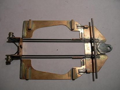

Here is the completed chassis before it takes a dip in the sink with a little comet and an sos pad. A 280 grit buffing wheel was used to clean up any excess solder around all joints.

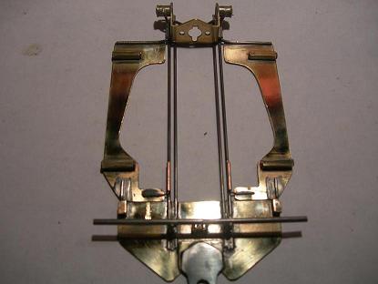
And the grand finish! After drying the chassis it received a quick polish using some Brasso and a cotton buffing wheel on the Dremel at medium speed. I just applied the Brasso with a paper towel and worked on each piece of the chassis individually.
Total build time, from cutting out pieces, fitting, and interruptions, was about nine hours. Next time will be much quicker as now I have templates. In race trim it will weigh in at about 106.5 grams. Guide lead is 7/8". Wheel base is 4-1/4".
- Jaak likes this
A motor is only as fast as the chassis it's in.
Dominic Luongo
Like Dominator Custom Chassis on Facebook
NERR photos from 2012-April 2016
NERR photos from 2016 to now
#23

Posted 15 June 2008 - 12:38 PM
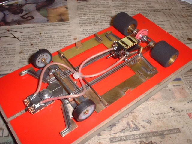

The chassis has no hinges and uses only flex movement. The pans lift in the rear and are captured with 3/32" square tubing. The 1/16" main frame is made from one piece and the inside rails are stiffen with .055" wires. The nosepiece is suspended at the front and actually rocks up and down. The back pin tubes are held in with one retainer in a notch; normally you would use two retainers. And the oilites are notched to slip inside the motor bracket, making a stronger joint.
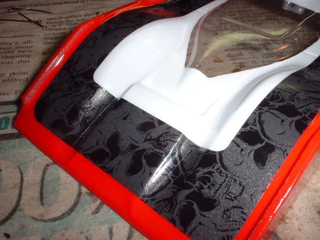
BTW: check out the spooky graphics on the race body.
- Jaak likes this
First Place Loser in the JK Products
International D3 Builders Competition
#24

Posted 28 June 2008 - 02:37 PM
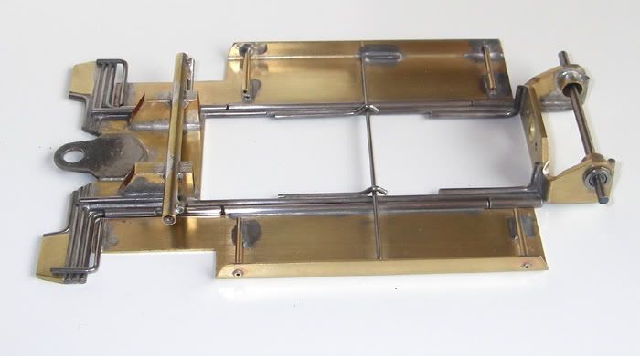
Rear closeup shows a handmade shallow bracket of .063" brass. This is bent to move the axle close to the motor but not so close that only the tiny bronze gears will work. This is a hypoid and will clear a Parma gear up to a 27t. Rear retainer tube for the faux plumber is about .015" over the rail diameter, allowing a bit of flex plumber movement.
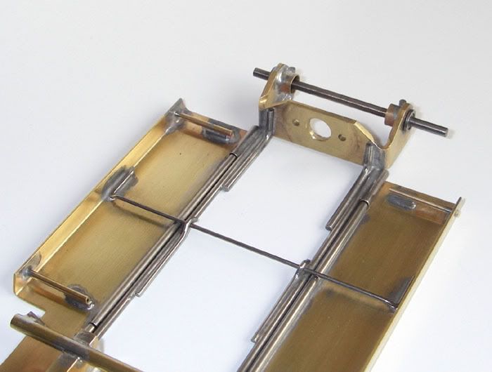
Front closeup shows the .063" brass nosepiece, box tubing for axle supports. and .062" outriggers to support the axles. Pan crosspiece is .040" wire which is soldered to the pans but not to the rails. Free hinge movement is minimal but there is a fair bit of travel in the pan setup. All movement is under tension from the crosspiece or the flex of the plumber rail.
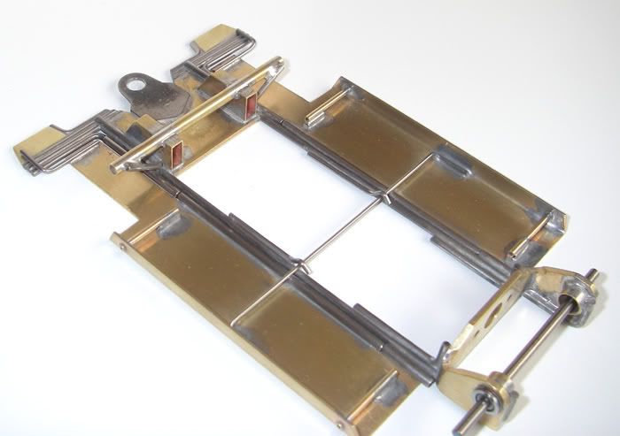
Track testing today or tomorrow. This is stiff enough for a Big Dog on a banked track but should still be good for a Falcon on a flat track as well. I won't be surprised at all if the pan crosspiece needs to become .047" wire. Or get soldered in place to the main rail; that'll be an easy modification.
- Jaak, Terry Tawney and C. J. Bupgoo like this
#25

Posted 07 July 2008 - 12:31 AM
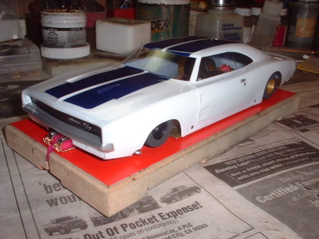
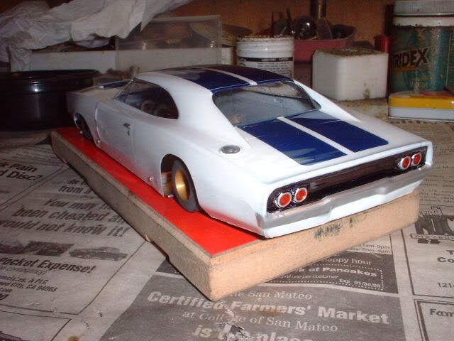
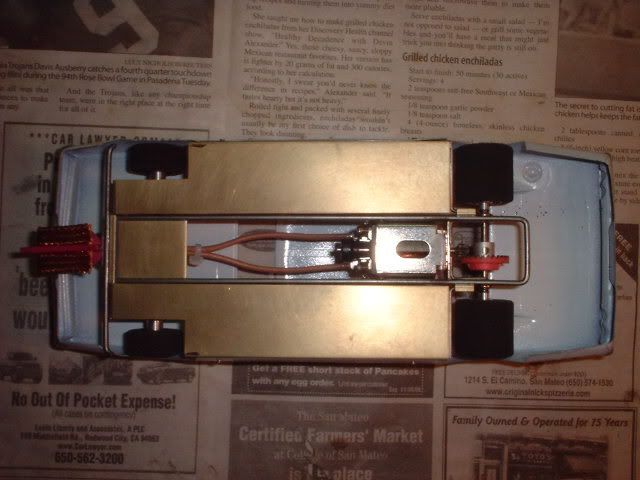
The chassis is the same as my production chassis except for the 4-5/8" long wheelbase. I meant for it to be 4-1/2", but accidentally went aboard on this build. The weird thing is it doesn't handle half bad. The motor is a stock Chinese Parma 16D, geared at 7/28. I'll test it at SCR's Blue King before I make any other changes, but for now, I kinda like this car.
- Jaak likes this
First Place Loser in the JK Products
International D3 Builders Competition


