Scratchbuilt chassis gallery
#26
Posted 13 July 2008 - 09:22 PM
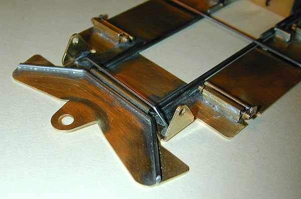
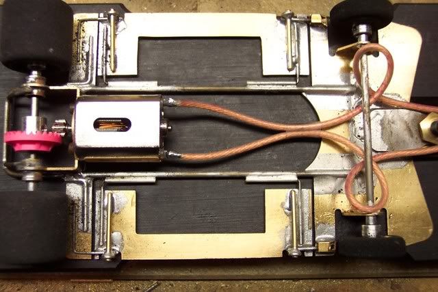
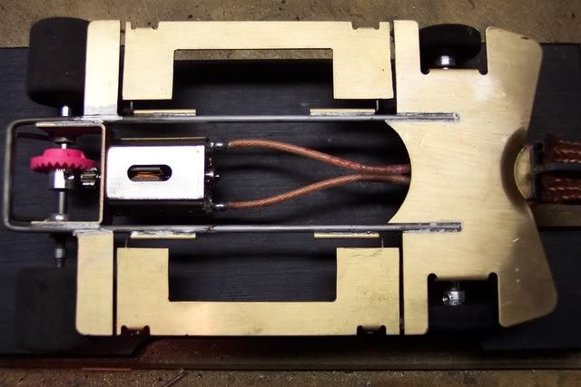
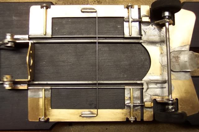
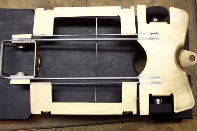
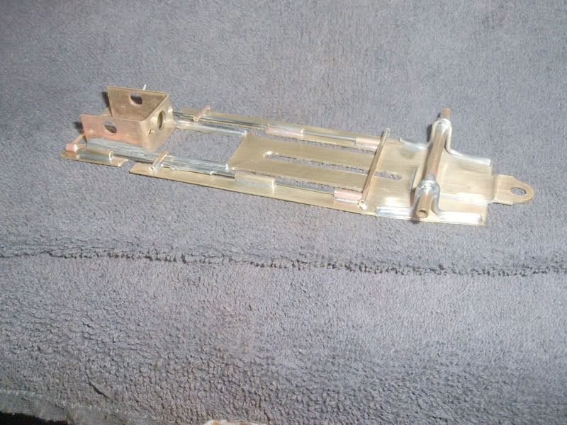
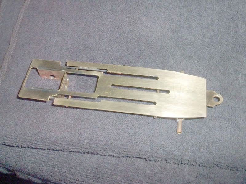
This chassis is made from the .078" kit. It uses a plumber set-up and has the front tires attached to the pans.
This picture shows the two alternative body mounting techniques. The floating mounts should give a less tight setup that the fixed mounts.
The holes in the front axle uprights have been enlarged on the bottom half to reduce binding during pan movement.The axle is not soldered and the front tires rotate independently.
- Jaak likes this
#28
Posted 02 August 2008 - 05:53 PM
Joe "Noose" Neumeister
Sometimes known as a serial despoiler of the clear purity of virgin Lexan bodies. Lexan is my canvas!
Noose Custom Painting - Since 1967
Chairman - IRRA® Body Committee - Roving IRRA® Tech Dude - "EVIL BUCKS Painter"
"Team Evil Bucks" Racer - 2016 Caribbean Retro Overall Champion
The only thing bad about Retro is admitting that you remember doing it originally.
#29
Posted 05 August 2008 - 12:40 PM
Brass is all .032" and an .063" main rail. Pans will be attached to the nose by the .063" wire shown and possible a hinge in the front similar to by previous build on post 22, rear of the pans will be the same. Pans will also be 1.2 grams heavier than the previous set show in post 22. Nose piece will be 2.7 grams heavier.
Now where did I put that motor bracket?
- Jaak likes this
A motor is only as fast as the chassis it's in.
Dominic Luongo
Like Dominator Custom Chassis on Facebook
NERR photos from 2012-April 2016
NERR photos from 2016 to now
#30
Posted 10 August 2008 - 12:01 PM
Took a while to get all the 'bits' you always remember you need... after you come home and get into building!! LOL!
Also... I must admit it has taken me a while to think about these cars and some designs... as realistically... apart from waaay back when I was much, much younger... ahem... cough, cough, wheeeeze...
I have mainly raced 'wing cars'... and was, as I guess were many here also, a 'gooaAddict'... LOL!
So it has been an interesting process... helped in some ways by my 1/32 scale experience perhaps... and NOT hindered by the progressively un-square 'false start'... (now pulled apart and never to be shown!!... LOL!)
I have always been interested in the idea of static and/or floating/isolating weight and general isolation, etc., in chassis and had my mind heading in those directions when I saw a couple of Steube chassis that were doing the same thing and also (apart from many, many Other), was also strangely intrigued by TonyP's 'Aero' chassis. Especially, as I had already started to head in that direction.
Hope you don't mind, Tony??, LOL!! ...No 'venturis' one this on... YET!! LOL!!
But I guess is also a progression of a similar idea.
So this is built for the FLAT Track shown Here; in the Aussie Retro thread it has some Tight corners,..but is Deceptively Fast with a couple of Tricky bits! and if you get it right, is both Challenging and satisfying, (or Frustrating,..lol), to drive,
It's funny though,..isn't it,..there is something about the 'Balance' and 'Feel' of a car when you are building it,..they often just feel right!,..
So far,..I am happy with how this build has been going,..I have kind of let the 'Car' lead Me!,..
It's Not Yet completed,..but I was trying to make something I could 'Cut' or 'Add' to easily and was thinking of a 'Heavier than Flyweight' chassis, for Stability in the Race,..Not TQ'ing !!!,..rofl
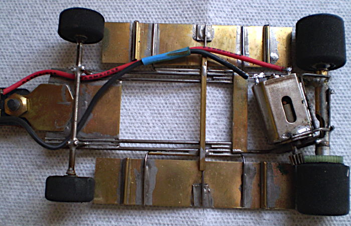
Like Tony's car, I had also started out with a very similar idea at the front and for pans, but was intending to hinge them at the Rear, but at the Moment, have them temporarily attached to an .047 'Spring' (in Effect), located straight through the Motor box. The 'Notched' Rear Pans are Solidly Mounted to the Chassis.
It uses one of those 'Chintsy' motor brackets, but it isn't really doing much apart from locating the Motor and giving me a 'Distance' locatorl for the rear axle tubes.
The Main Rails ar .063 &.055, with .063 Brass rod 'bits' added and possibly to Be added.
As stated above,..I had been thinking of Leaving some weight Low and Hinging the Body,..so at this stage, I have Yet to add the Various Body 'Mounts'/Pseudo Pan Hinges.
Although for this First race,..we are trying to Keep it simple,..(In fact Only Hinges for Pans etc,..No Plumbers),..I couldn't Help but try something Just that little bit 'out of the Ordinary' !!,..
As at this stage I am unsure how or what will proive to be the Best method for mounting the body,..I am intending to Try both Rattle type mounts as well as and in Combo with Hinged/hinges.
Will post any Future Further positive developments,..hope you like it,..comments, criticisms, suggestions etc all welcome,.,.
So Here is My 'Aussie Retro' chassis,..from a Distant,..but very 'Kindred' Slottie Spirit !!,..:D
- Jaak likes this
#31
Posted 13 August 2008 - 09:05 AM
The Outriggers, are Hinged at the front, but are 'Sprung and Located' by a piece of .047 wire running across behind the Motor Bracket.
Before I got too carried away with the design,..Fox and I went to the track today,..so it has had it's First run and so far,..am Extremely Happy with it's Confident Handling.
I have Yet to Fine Tune the "Pans', Movement, but even with Just the 'Spring', it shows Great Promise. !!! ,..
in fact have even been considering 'Cutting' the Pans in Half, to Provide Quadrants as such
I Was trying for a 'Comfortable' RACE Chassis and so far,..so Good, .
It's actually Quite flexible and at this stage would Not seem to require any lead,..but testing will continue.
I guess it is a bit longer than Normal, it being 4 9/10ths Guide lead and a 4 1/4 wheel base,..seems OK,..
The Chassis is withing 1 or 2 tenths of the Fastest time set so far,.around our Flat Track
,...Practice race on Friday Night,..with Our First D3 race on Saturday evening,..Looking forward to it !!!
- Jaak and 7D7 Hobbies like this
#32
Posted 18 August 2008 - 09:04 AM
When I first assembled my D3 kit by JK, I decided to use 1/8 inch tubing to construct my hinges from. I set them low on the chassis as should be done and then found out that I could not meet the 3.125 max chassis width spec. I asked about notching the pans, but that was not permitted. I could have gone to 1/16 inch tubing and smaller diameter wire, but I chose another route. I simply mounted the 1/8 inch tubing on top of the pans, then made the remaining part of the hinge from .035 wire. The spacing seems to work out quite nicely as no shimming is required to get the chassis flat on the jig. I kind of like the way I went. But with the JK kit, I'm sure there will be a lot of variants.
Here what it looks like now:
Now it's time for a good cleaning to remove all the acid flux and leftover solder and it should be ready to race at the 110 gram weight class as intended.
My JK Ti22 body came in this weekend. What a sweet body that is! If it stays nice out today, there will be some time spent in the paint booth!
1/24/48-2/18/16
Requiescat in Pace
#33
Posted 20 August 2008 - 05:46 PM
The chassis as is weighs in at 50.5 grams so once everything is added it will be about 1-2 grams under the minimum so plenty of room for adjustment.
A motor is only as fast as the chassis it's in.
Dominic Luongo
Like Dominator Custom Chassis on Facebook
NERR photos from 2012-April 2016
NERR photos from 2016 to now
#34
Posted 23 August 2008 - 10:57 AM
#35
Posted 26 August 2008 - 09:50 PM
My starting points are all from the bottom of my spare chassis box. lol One is an old Parma BrassKar (thanks Mr. Hershman for the ID) and the other is some random plumber wing car chassis. Here's hoping this works!
#36
Posted 08 September 2008 - 05:28 PM
I used an R-Geo 3/4" rear bracket with .078" mainrails.
#37
Posted 12 September 2008 - 08:26 PM
Hey, those BrassyKar chassis are a great place to start. Lots of good parts and the best part, it's just sitting there!
I chose to build mine into a GT Coupe entry. With body, ready to race it weighs 110.2 grams.
Watch garage sales and such for 'supplies'!
1/24/48-2/18/16
Requiescat in Pace
#38
#40
Posted 14 September 2008 - 12:39 PM
Rick Bennardo
"Professional Tinkerer"
scrgeo@comcast.net
R-Geo Products
LIKE my Facebook page for updates, new releases, and sales: Rgeo Slots...
Lead! The easy equalizer...
#41
Posted 16 September 2008 - 08:18 AM
Please remember that any comments, questions, or discussions regarding the chassis posted to this Chassis Gallery need to be made in the Discussion thread. See post #1.
Gregory Wells
Never forget that first place goes to the racer with the MOST laps, not the racer with the FASTEST lap
#43
Posted 22 September 2008 - 08:47 AM
I knew the design worked so I decided it to give it a try myself with a couple of things in mind. First, the longer wheelbase, and second, make it a bit lighter to get to around 105 grams total. This has a 4" wheelbase and 15/16" guidelead. Don't have a tumbler so it was just a wash up on this one.
- Steve Turner likes this
Joe "Noose" Neumeister
Sometimes known as a serial despoiler of the clear purity of virgin Lexan bodies. Lexan is my canvas!
Noose Custom Painting - Since 1967
Chairman - IRRA® Body Committee - Roving IRRA® Tech Dude - "EVIL BUCKS Painter"
"Team Evil Bucks" Racer - 2016 Caribbean Retro Overall Champion
The only thing bad about Retro is admitting that you remember doing it originally.
#44
Posted 28 September 2008 - 01:08 PM
Rick Bennardo
"Professional Tinkerer"
scrgeo@comcast.net
R-Geo Products
LIKE my Facebook page for updates, new releases, and sales: Rgeo Slots...
Lead! The easy equalizer...
#46
Posted 03 October 2008 - 08:55 PM
Rick Bennardo
"Professional Tinkerer"
scrgeo@comcast.net
R-Geo Products
LIKE my Facebook page for updates, new releases, and sales: Rgeo Slots...
Lead! The easy equalizer...
#47
Posted 05 October 2008 - 12:50 AM
Same rail structure as the last one (1 x .063", 1 x .055", with a bit of 1/16" brass rod in the rear).
A couple of 'spare' pans of Rick's, well, what is left of 'em,..
I have the motor a bit closer to the rear axle as well on this one and the pear panlets are .063" as well, which might be a bit heavy (might change them).
Haven't weighed it accurately, but it must be close to the last one... say about 120 grams.
I must admit, this car argued with me quite a bit during the build... (as can be seen by the odd bit of solder here and there that had the obvious outcome!!... ROFL)... but has ended up 'feeling' OK. Time will tell.
Soldering is a bit 'slack' as well... sigh... out of practice as well I guess... ROFL... gotta get a better light for late night builds!!!
Have yet to run it, but will give it a run next week at Area 3.
#48
Posted 15 October 2008 - 08:12 AM
This chassis has square tubing and wires situated on the inide and outside of the pans to simulate floppy action.
This picture show the "floppy" movement of the chassis
This picture shows the movement limiters, created from 1/8" square tubing and piano wire.
This picture shows the wires in the tubing. Note that the inside wire is larger than the outside, nearly filling up the opening in the tubing. This aids in the "floppy" movement and prevents reverse floppy movement when downforce is applied to the body. Should this occur, the chassis would drag on the outside.
This picture shows the rear chassis movement. Here, all wires are the same diameter.
#49
Posted 02 November 2008 - 09:35 PM
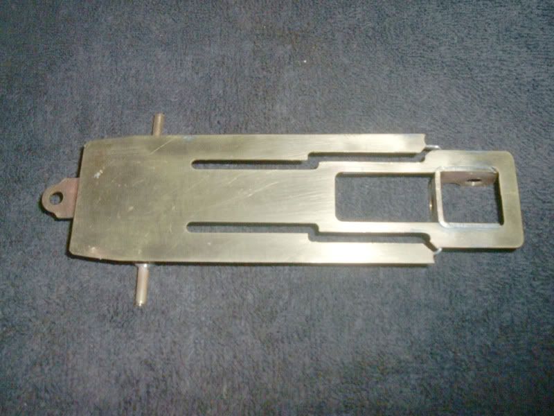
Top view
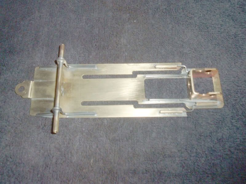
Bottom
Front assembly
Close up of front hinge
11/27/57-8/12/22
Requiescat in Pace