Jump to content


Photo

IRRA™ JK Spec Class chassis build


  • Please log in to reply
75 replies to this topic

#1 MSwiss

MSwiss

    Grand Champion Poster

  • IRRA National Director
  • PipPipPipPipPipPipPipPip
  • 25,855 posts
  • Joined: 16-April 06
  • Gender:Male

Posted 05 September 2008 - 10:41 PM

Shortly after Joe "Noose" Neumeister launched the IRRA™ website, a discussion started on doing some "How-to" articles. The thought was we needed one that would help the new racer or someone with very little chassis building experience.

It made sense we use a JK chassis kit since the IRRA™ had just started a JK Spec Class geared for non-experts.
With having a request from a customer, Jimmi Bostrom, for a JK RTR chassis, it made sense I take some pictures while building it. The torsion-style pan flex he wanted would be a bit easier to build vs a hinged model. Also, I kept the bends as simple as possible on the six pieces of wire I used.

It was also suggested, if possible, build it without using a jig to help someone who hadn't purchased one yet.
I went ahead and did that. While I used my circa 1984, slate wing car chassis jig, I didn't use the guide post or
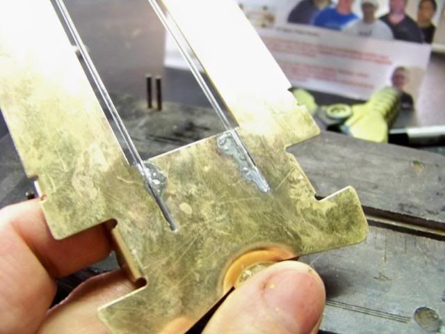
any of the scribed markings. I only used it because it's on legs which facilitated clamping.

The finished article is admittedly "Minutia Mania". I did it with the only assumption being, the reader would
know what end of the soldering iron to hold.

I wanted it to have a similar feel as the benchmark series of building articles Lee Gilbert did for Car Model in 1973.
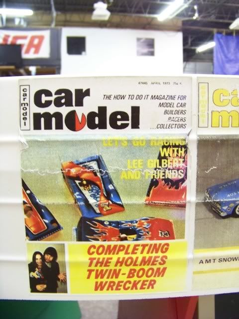
000_0562.jpg

I stopped short of asking my fiancee to clean the chassis while taking a bubble bath, like Lee was able to convince Donna to do.

But hopefully I injected enough levity for the reader to utter at least once, the most heard phrase at Chicagland Raceway's Saturday night races:

"Swiss, there must be something seriously wrong with you."*

*© 2005 - "Sano" Dave Fiedler
  • tootfalusi likes this

Mike Swiss
 
Inventor of the Low CG guide flag 4/20/18
IRRA® Components Committee Chairman
Five-time USRA National Champion (two G7, one G27, two G7 Senior)
Two-time G7 World Champion (1988, 1990), eight G7 main appearances
Eight-time G7 King track single lap world record holder

17B West Ogden Ave., Westmont, IL 60559, (708) 203-8003, mikeswiss86@hotmail.com (also my PayPal address)

Note: Send all USPS packages and mail to: 692 Citadel Drive, Westmont, Illinois 60559


#2 MSwiss

MSwiss

    Grand Champion Poster

  • IRRA National Director
  • PipPipPipPipPipPipPipPip
  • 25,855 posts
  • Joined: 16-April 06
  • Gender:Male

Posted 05 September 2008 - 10:42 PM

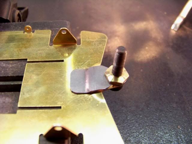
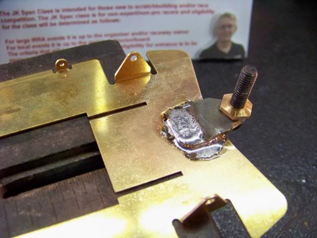
We'll start with adding a guide tongue brace.

Even though I sell them, I don't think they're that necessary. But since the chassis is for a customer who likes all the bells and whistles, I'll throw one on.

Since I said I wasn't going to use a jig, I'll just use a 10-32 machine screw with a Sonic brass nut to keep it aligned.

Posted Image

The IRRA Gang of Seven (Go7) are back-seat builders. They're reminding me to make sure I clamp the chassis with the area to be soldered, hanging off the end, so the block doesn't act quite as much like a heatsink.

While you want to make sure you get the chassis parts hot enough for the solder to flow, there's no reason to overheat them. While more so with aluminum, which won't be used, in extreme cases, you can start softening metal up.

Posted Image

#3 MSwiss

MSwiss

    Grand Champion Poster

  • IRRA National Director
  • PipPipPipPipPipPipPipPip
  • 25,855 posts
  • Joined: 16-April 06
  • Gender:Male

Posted 05 September 2008 - 10:43 PM

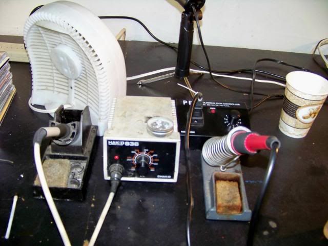
The tools of the trade. For general soldering, I really like the Hakko 936/907 combo. It's super-light and super-comfortable to use with a real flexible cord from the iron to the heat control. Unfortunately, it's also expensive and hard to find the thicker, heavier duty element. The one you see at places like Fry's is lighter duty for electronics use.

For the even heavier duty, I got the 100 watt unit on the right. It's very similar to the Inland 60105 and the tips are interchangable. If you go with only one, I would buy the Inland and make sure you get something like their 60014 temp control or the 60020 soldering station that incorporates one.

Always use a fan to suck the fumes away. Inland makes a nice fume trap (60010) but this $6.95 desk fan will suffice.

Also shown in the lower left hand corner is a small white flux brush (M424) that Koford sells for about 89 cents. Whatever it's made of, it's got the longest lasting bristles I've come across in a separate brush. Go ahead and trim the bristles to a sharper point for finer control applying the flux.

Posted Image

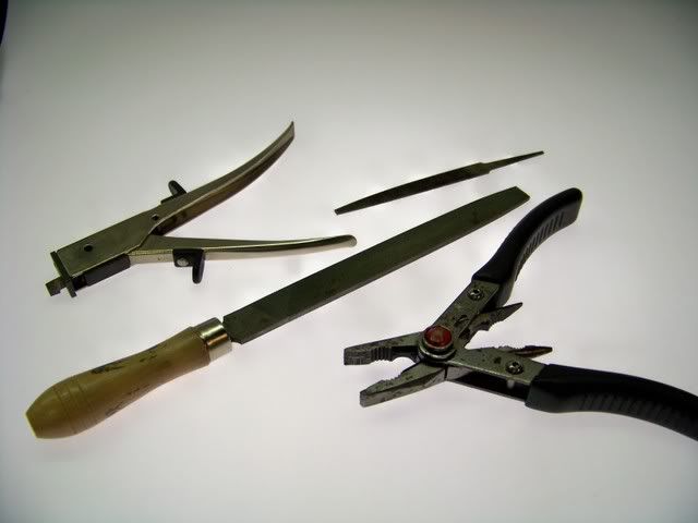
Here's some other items I'll be using:
Small file
Large file
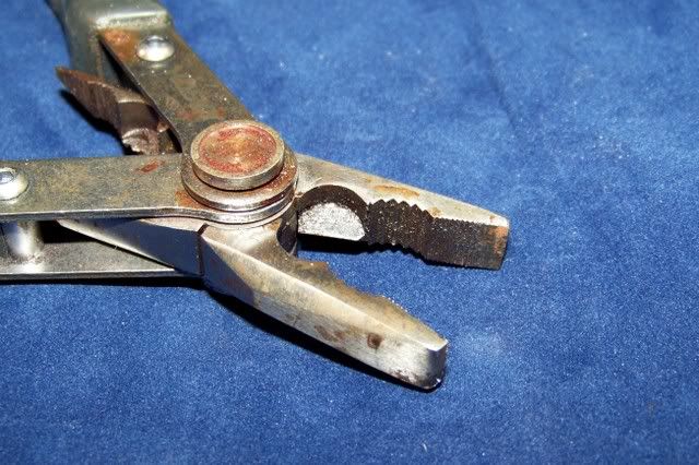
Large pliers
Nibbler (brass notcher)

Posted Image

I bought these Husky brand pliers at Home Depot. The goofy feature that flips the handles over for needle nose use is a real nuisance. Despite that, the stout, square jaws produce nice, crisp bends in .063" wire.

Posted Image

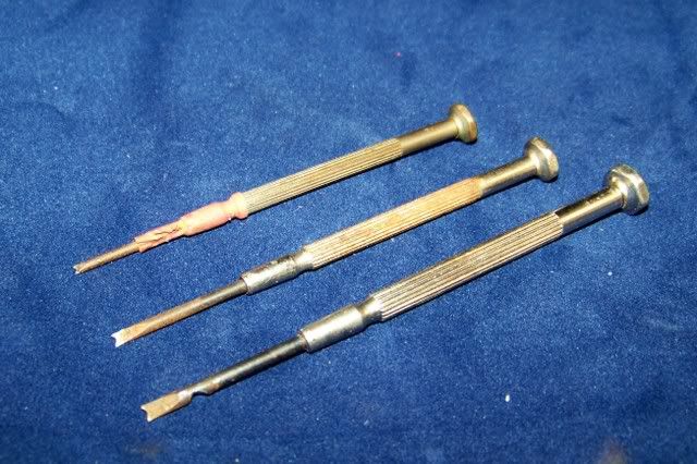
Not to be overlooked are some good "hold-downs". I've tried different things over the years, but I always go back to jewelers screwdrivers that I have ground several size notches in. Being short and having comfortable knobs makes using two at once with the same hand possible. Being skinny and heatproof is also important.

Posted Image

#4 MSwiss

MSwiss

    Grand Champion Poster

  • IRRA National Director
  • PipPipPipPipPipPipPipPip
  • 25,855 posts
  • Joined: 16-April 06
  • Gender:Male

Posted 05 September 2008 - 10:45 PM

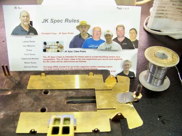
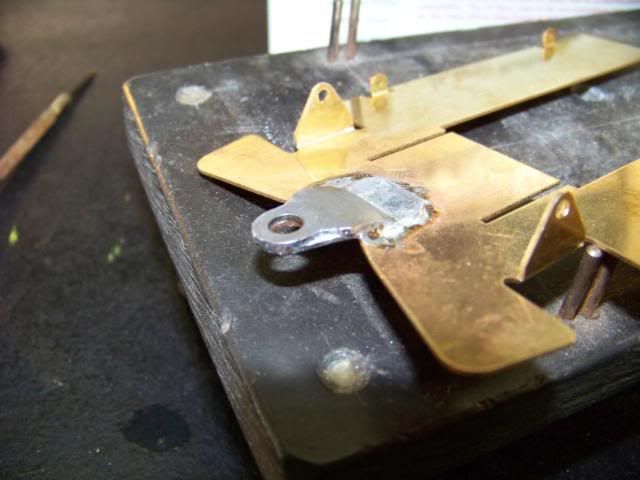
Make sure the top plate of the guide brace is on parallel to the existing bottom integral brass guide tongue.
Tighten the nut just enough to hold things aligned. Use your small brush to apply some acid flux in the back area
as shown.

Don't get too carried with the flux or solder. Otherwise capillary action will have flux and solder flowing too
far forward and you'll solder that bolt and nut into place. Use the 100 watt iron at maximum temperature.

Use rosin core 60/40 like you can usually buy from Radio Shack. If you're in scratchbuilding for the long haul, buy a few rolls before it gets totally phased out.

For acid flux, make sure it's strong enough your skin tingles when a bit gets on it. Use something at least as good as Stay-Clean. I also sell some that will have you hustling to the sink to wash it off even quicker.

Posted Image

#5 MSwiss

MSwiss

    Grand Champion Poster

  • IRRA National Director
  • PipPipPipPipPipPipPipPip
  • 25,855 posts
  • Joined: 16-April 06
  • Gender:Male

Posted 05 September 2008 - 10:45 PM

Once cool, remove the nut and bolt.

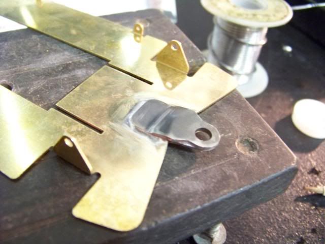
Now you can go back and touch up the front, adding flux and solder to the area around the pivot hole. Do one side at a time, allowing a little cooling time in between, so as not to disturb that first solder joint towards the back.

Posted Image

#6 MSwiss

MSwiss

    Grand Champion Poster

  • IRRA National Director
  • PipPipPipPipPipPipPipPip
  • 25,855 posts
  • Joined: 16-April 06
  • Gender:Male

Posted 05 September 2008 - 10:46 PM

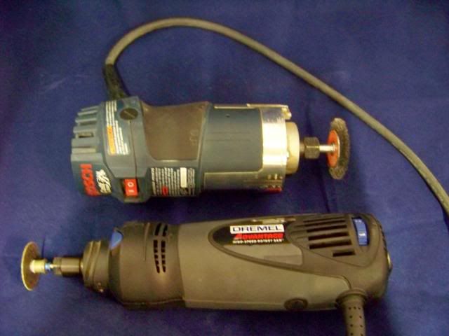
Since my four other rotary tools are hard-wired into another work area (so the cords don't tangle), I'll just use my heavy duty stuff for the polishing and cutting.

On top is a Bosch variable speed trim router with a 2" diameter wire brush. It works real well but you have to be real careful you don't try to get in too tight of a corner or things go flying and stuff gets bent.

Make sure you get a wheel fine enough it won't scratch the brass, but heavy enough to remove excess solder. Also, make triple-sure you have good eye protection and be prepared to catch some wire ends in your clothes and skin (especially when the wheel is new).

I'll also show at the end of the article, a more expensive, but safer and less painful alternative for removing solder.

At the bottom is a Dremel Advantage. It's basically a low-end RotoZip. It's super-powerful and, at $39 when on sale at Menard's, is a great bargain.

Combined with the Dremel EZ-Lock, large diameter, fiber-reinforced cutting discs, even 3/32" piano wire is a breeze to cut.

Posted Image

#7 MSwiss

MSwiss

    Grand Champion Poster

  • IRRA National Director
  • PipPipPipPipPipPipPipPip
  • 25,855 posts
  • Joined: 16-April 06
  • Gender:Male

Posted 05 September 2008 - 10:46 PM

Neutralize the solder joint with some soapy water and a small rag or sponge.

Clean off the excess solder with the wire wheel. Make sure you do it now before the axle gets soldered into place.

Posted Image

#8 MSwiss

MSwiss

    Grand Champion Poster

  • IRRA National Director
  • PipPipPipPipPipPipPipPip
  • 25,855 posts
  • Joined: 16-April 06
  • Gender:Male

Posted 05 September 2008 - 10:47 PM

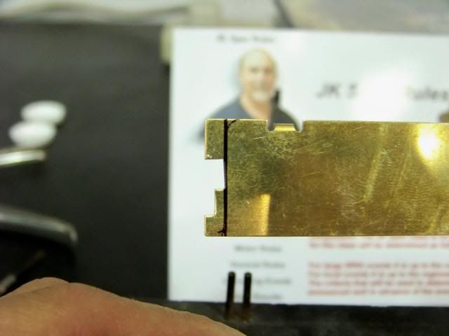
I'll be using approx. a 4.00" guide lead so the back of the pans will need to trimmed back a bit for tire clearance. I have the luxury of a finished chassis to "mirror up" to it to mark how much needs to be cut.

You'll be removing about .150". This will leave the length of the pans as about 3.250" from the back edge to the BACK notch of the front wheel cut-out.

Posted Image

#9 MSwiss

MSwiss

    Grand Champion Poster

  • IRRA National Director
  • PipPipPipPipPipPipPipPip
  • 25,855 posts
  • Joined: 16-April 06
  • Gender:Male

Posted 05 September 2008 - 10:47 PM

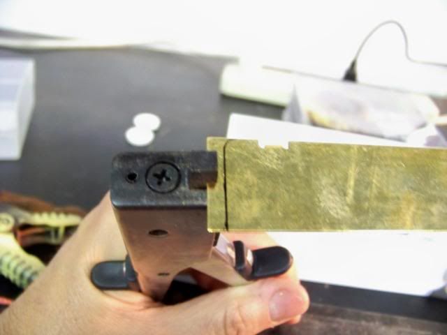
Even if you are very steady with your Dremel and a cutting disc, it will still need a bit of clean-up with a file when you're done. Thus, whenever I can use my nibbler to trim brass, I do. Less heat and less brass dust flying around.

I prefer the relatively inexpensive, Taiwan-made model Radio Shack usually has. It cuts .032" brass like butter. Don't attempt to use it on .064".

Posted Image

#10 MSwiss

MSwiss

    Grand Champion Poster

  • IRRA National Director
  • PipPipPipPipPipPipPipPip
  • 25,855 posts
  • Joined: 16-April 06
  • Gender:Male

Posted 05 September 2008 - 10:47 PM

A full "bite" is approximately .075" deep, so two of them will be just about perfect.

Posted Image

#11 MSwiss

MSwiss

    Grand Champion Poster

  • IRRA National Director
  • PipPipPipPipPipPipPipPip
  • 25,855 posts
  • Joined: 16-April 06
  • Gender:Male

Posted 05 September 2008 - 10:48 PM

After smoothing out the nibbler cuts with a file, for aesthetics, check to see the end of the pans are fairly square and even.

Posted Image

#12 MSwiss

MSwiss

    Grand Champion Poster

  • IRRA National Director
  • PipPipPipPipPipPipPipPip
  • 25,855 posts
  • Joined: 16-April 06
  • Gender:Male

Posted 05 September 2008 - 10:49 PM

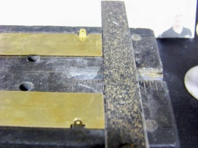
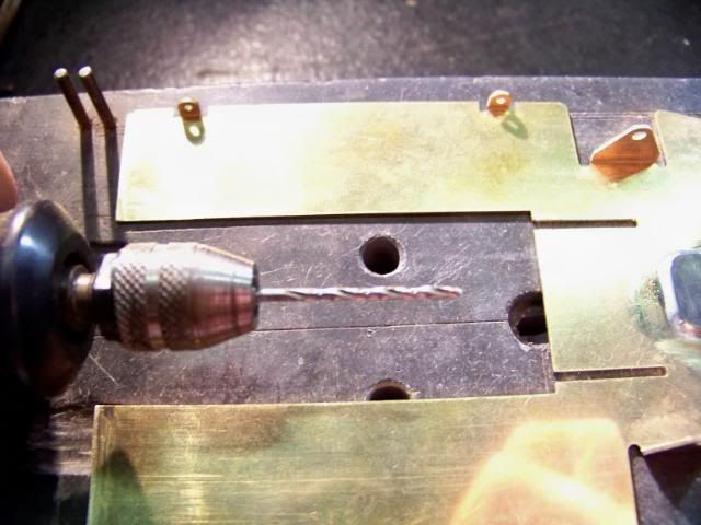
The slots, IMO, are even a little tight for .063" wire, so they need to be opened up just a tad. I didn't have a .063" straight grinding burr handy, so I made do with a 1/16" drill bit. You'll need the 1/16" bit for later, anyway.

Just run the rotating bit (perpendicular to the slot) back and forth, until the .063" wire rail will drop in flat, without any resistance.

Posted Image

#13 MSwiss

MSwiss

    Grand Champion Poster

  • IRRA National Director
  • PipPipPipPipPipPipPipPip
  • 25,855 posts
  • Joined: 16-April 06
  • Gender:Male

Posted 05 September 2008 - 10:50 PM

For the 4" wheelbase we'll be using, shorten those narly ends of the .063" main rail approx. .093", squaring them off in the process. When done, stand the end of the rails on a flat block. Both rails should stand perpendicular/90 degrees to the block. If not, sand the long end slightly until it does.

After a few attempts at tweaking it to lay flat, I went ahead and cut it in half in the back. This allowed each L-shaped side to lay nice, flat, and "relaxed".

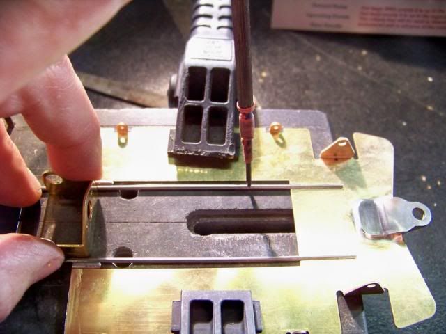
Shown is my left hand doing some contortions with four of my five fingers. Since I'm not using a jig, I'm holding the bracket with my middle finger and thumb while the index finger is holding down a notched screwdriver for the front of the rail and the other finger is keeping the back of the "L" from rotating up.

After putting down the camera, I soldered the rail in the notch using the 100 watter.

Obviously, repeat for the other side.

Posted Image

#14 MSwiss

MSwiss

    Grand Champion Poster

  • IRRA National Director
  • PipPipPipPipPipPipPipPip
  • 25,855 posts
  • Joined: 16-April 06
  • Gender:Male

Posted 05 September 2008 - 10:51 PM

If you're careful applying the flux, you can get some fairly neat solder joints. I just concentrated on the inside as braces will added later to the outside of the rails.

Posted Image

#15 MSwiss

MSwiss

    Grand Champion Poster

  • IRRA National Director
  • PipPipPipPipPipPipPipPip
  • 25,855 posts
  • Joined: 16-April 06
  • Gender:Male

Posted 05 September 2008 - 10:52 PM

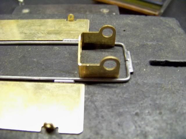
Lets go ahead and reconnect the rails in back. I just used one of my pre-cut pieces of 1/16" brass tubing because the ends are perfectly square and burr-free.

Posted Image

#16 MSwiss

MSwiss

    Grand Champion Poster

  • IRRA National Director
  • PipPipPipPipPipPipPipPip
  • 25,855 posts
  • Joined: 16-April 06
  • Gender:Male

Posted 05 September 2008 - 10:52 PM

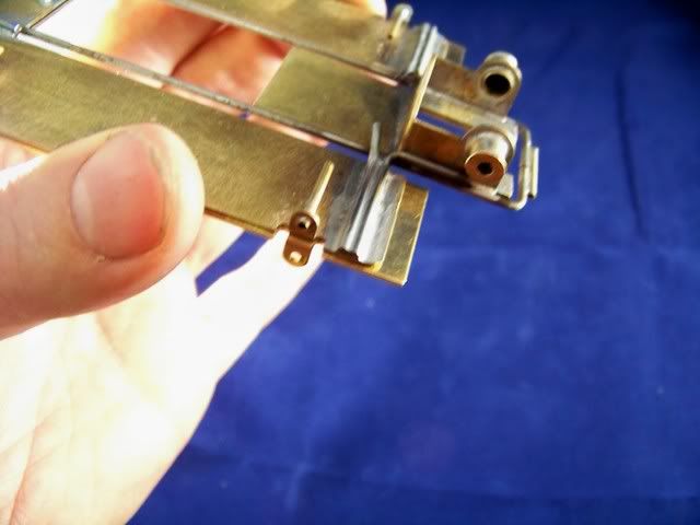
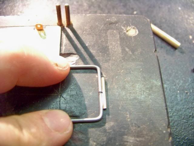
After moving my hands out of the way, you can see the two pins I used to keep everything straight and symmetrical while soldering the rails back together. What did the job were cut-off ends of a couple of worn-out Falcon VII arms. If you look close, you can see the notches I put on the end of all my armature shafts to help "key" in solder to prevent pinions from spinning.

I can now slide the bracket between the rails, up and back, with the same snug, but fairly light resistance. We'll get back to installing the bracket a little later.

Posted Image

#17 MSwiss

MSwiss

    Grand Champion Poster

  • IRRA National Director
  • PipPipPipPipPipPipPipPip
  • 25,855 posts
  • Joined: 16-April 06
  • Gender:Male

Posted 05 September 2008 - 10:53 PM

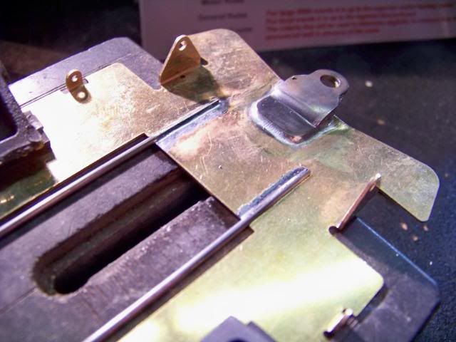
While this chassis will probably be run only on our flat track and won't need it, for the sake of the article, I'll go ahead and brace the front ears.

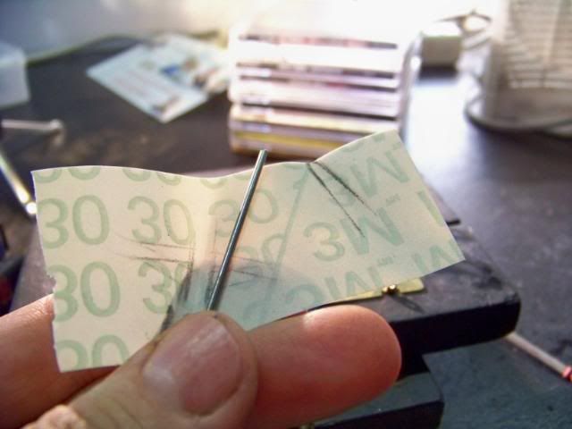
Take some .063" piano wire, and before bending it, clean it up so it solders real nice. Shown is some 3M 30-micron sanding film a customer gave me a big roll of a while back. It works great, but any fine sandpaper will do.

Posted Image

#18 MSwiss

MSwiss

    Grand Champion Poster

  • IRRA National Director
  • PipPipPipPipPipPipPipPip
  • 25,855 posts
  • Joined: 16-April 06
  • Gender:Male

Posted 05 September 2008 - 10:54 PM

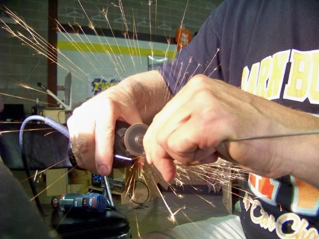
While the big Dremel with the big disc goes through .063" wire like nothing, it does throw off some pretty impressive sparks.

Don't even think of removing your eye protection while building.

Hope my Barn Burner shirt doesn't catch fire (no pun intended :) ).

Posted Image

#19 MSwiss

MSwiss

    Grand Champion Poster

  • IRRA National Director
  • PipPipPipPipPipPipPipPip
  • 25,855 posts
  • Joined: 16-April 06
  • Gender:Male

Posted 05 September 2008 - 10:54 PM

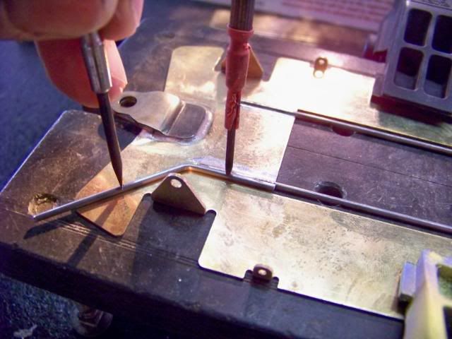
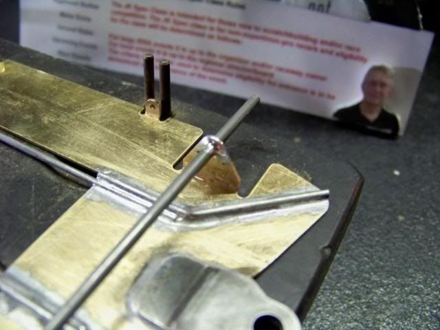
Bend the wire to an approximately 45 degree angle so it will run alongside the main rail and bisect the arc of the front ears. Trim it so the back end is even with the notch in the nose piece and it starts to bend where the main rail ends in the front.

Solder it in place, in the "well" on the outside of the main rail. Hold it down in two places, with two screwdrivers with notched Vs on the end, so it lays and stays flat.

Before your hand slips, tack one end down with the 100 watter. Go back and forth. The mass o' brass and the soldering block will be such an effective heat sink, as you move along with the iron, there should always be a spot that has cooled enough, it will keep the wire from moving.

Posted Image

#20 MSwiss

MSwiss

    Grand Champion Poster

  • IRRA National Director
  • PipPipPipPipPipPipPipPip
  • 25,855 posts
  • Joined: 16-April 06
  • Gender:Male

Posted 05 September 2008 - 10:55 PM

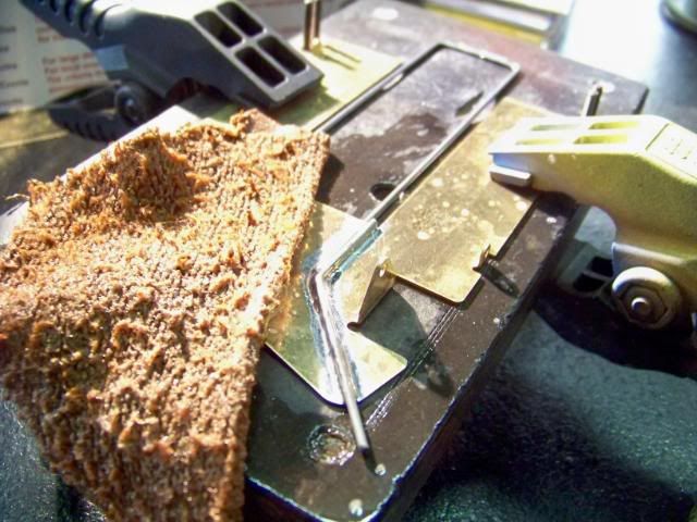
Get at that finished solder joint ASAP with the rag and soapy water.

Posted Image

#21 MSwiss

MSwiss

    Grand Champion Poster

  • IRRA National Director
  • PipPipPipPipPipPipPipPip
  • 25,855 posts
  • Joined: 16-April 06
  • Gender:Male

Posted 05 September 2008 - 10:56 PM

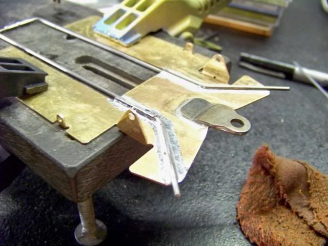
Go ahead and do the other side. If you were again careful, running a thin bead of flux along the wire, you'll get a pretty "contained" solder joint.

Rinse off the joint and trim the front ends of the wire even with the brass using the Dremel disk.

Posted Image

#22 MSwiss

MSwiss

    Grand Champion Poster

  • IRRA National Director
  • PipPipPipPipPipPipPipPip
  • 25,855 posts
  • Joined: 16-April 06
  • Gender:Male

Posted 05 September 2008 - 10:56 PM

Flip over the chassis and make sure solder flowed around the wire to the bottom of the slot. It has. The excess will be easily removed with the wire wheel.

Posted Image

#23 MSwiss

MSwiss

    Grand Champion Poster

  • IRRA National Director
  • PipPipPipPipPipPipPipPip
  • 25,855 posts
  • Joined: 16-April 06
  • Gender:Male

Posted 05 September 2008 - 10:57 PM

Go ahead and cut a piece of 3/32" piano wire for the front axle. Cut it a bit long (3.500") so you don't have to worry about centering it perfectly. It will be trimmed to length later.

Try not to flow solder on the outside of the upright. This will help in keeping the axle spacers square when you install the front tires. With the axle being captured in a hole, you don't need a spectacular solder joint.

Some guys insist on using a drill blank in front. I don't see why if the axle isn't going to rotate anyway.

Also, the 2.90" long Parma and 2.95" long JK "stocker" axles would need to be soldered perfectly on center to allow you to run the max 3.125" front track with the pre-trimmed JK8746PF fronts.

Posted Image

#24 MSwiss

MSwiss

    Grand Champion Poster

  • IRRA National Director
  • PipPipPipPipPipPipPipPip
  • 25,855 posts
  • Joined: 16-April 06
  • Gender:Male

Posted 05 September 2008 - 10:58 PM

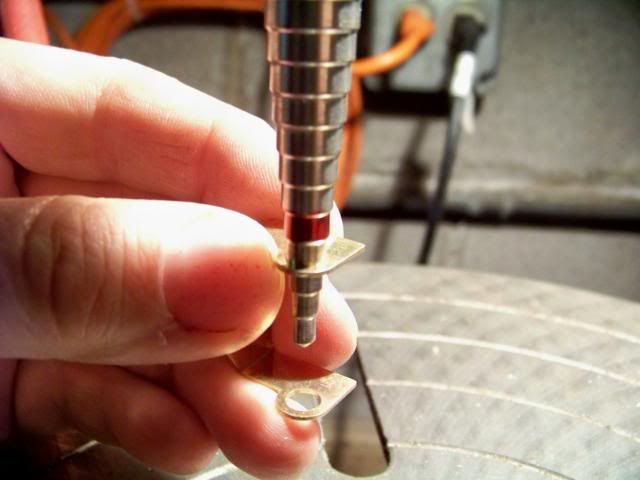
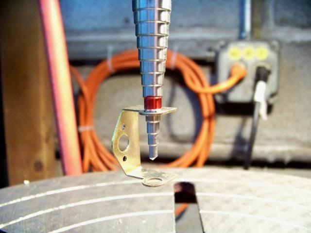
The JK bracket is designed to be used with a 7/32" axle tube. It's just a tad tight. An Irwin Unibit with 1/32" increments works great for this and any other application where you need to open up an existing hole.

In the case of the JK, you can just rotate the chuck by hand to open it up. Any kind of straight burr that will fit in the hole will also work. Just grind a tiny bit until the tube fits.

Posted Image

I painted the 1/4" band with armature stack/layout dye as a "warning" so I don't open it up too far.

Posted Image

#25 MSwiss

MSwiss

    Grand Champion Poster

  • IRRA National Director
  • PipPipPipPipPipPipPipPip
  • 25,855 posts
  • Joined: 16-April 06
  • Gender:Male

Posted 05 September 2008 - 10:59 PM

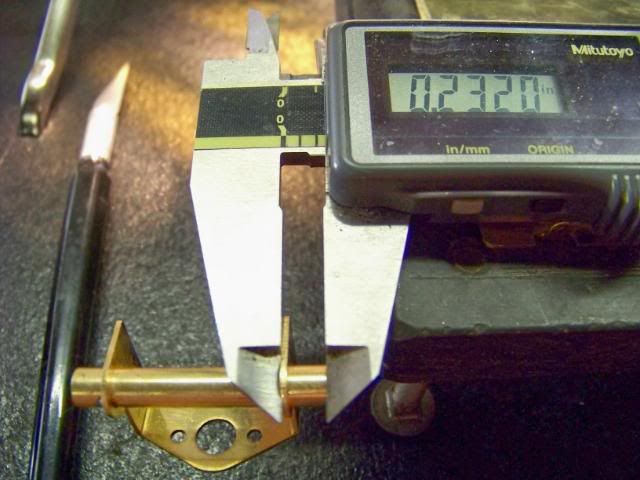
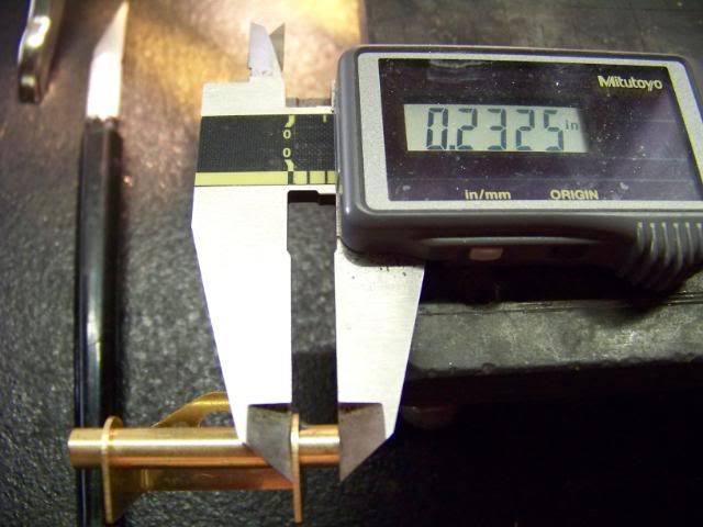
I used one of my 1.400" pre-cut axle tubes and moved it back and forth until it appeared centered. I confirmed this with my calipers and lightly tacked in one side in case I accidently moved it and it had to be readjusted.

Once I reconfirmed it was OK, I soldered the other side. I changed from side to side, each time, making sure the other side was cool, until I had nice smooth fillets of solder on both sides.

A .0005" diff is way better than close enough.

Posted Image

Posted Image


Electric Dreams Online Shop