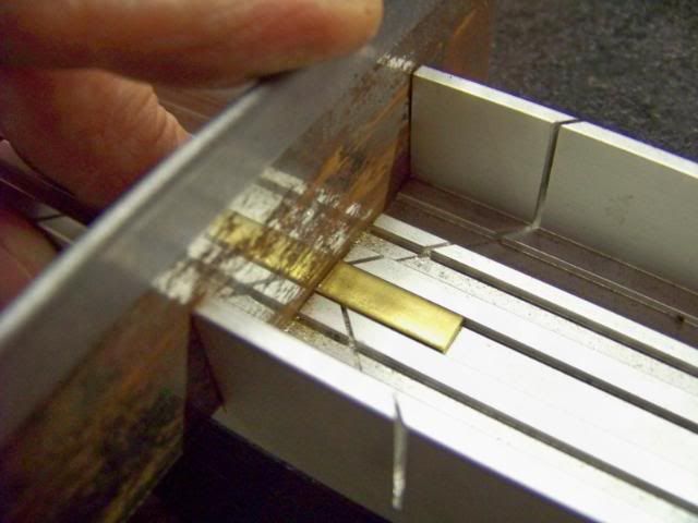
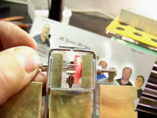
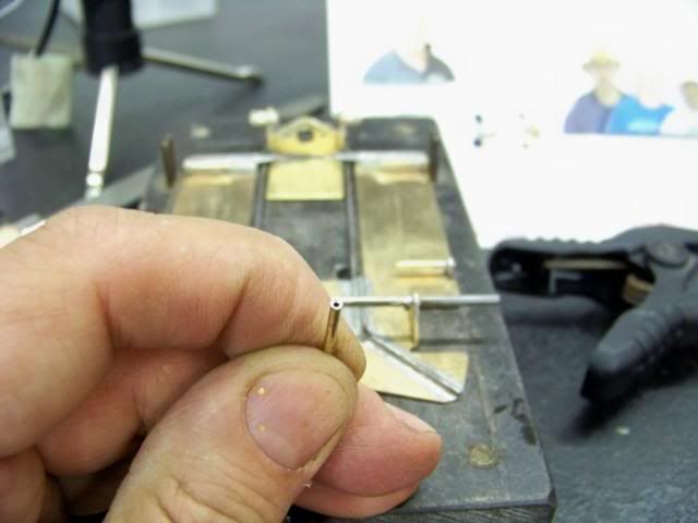
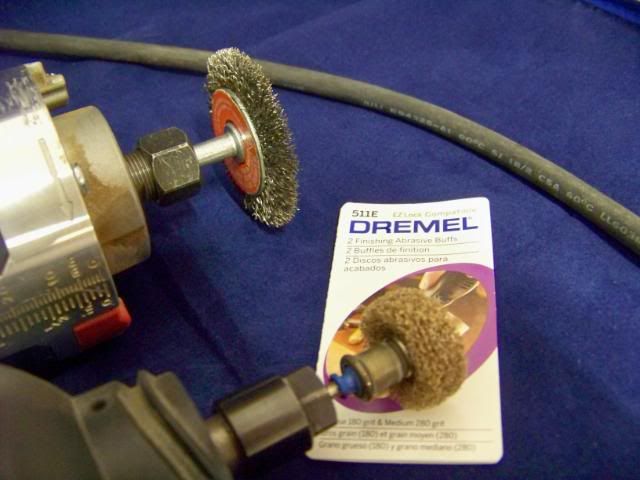
IRRA™ JK Spec Class chassis build
#26
Posted 05 September 2008 - 11:00 PM
I put the oilite on an axle and slowly feed it up into a spinning Dremel disk with my thumbnail. The disk will catch the knub and start spinning the oilite, trimming it pretty dead-on square.
The enclosed tube makes using a spring as a bushing alignment aid impractical. Still the perfectly square ends of a factory-cut tube makes installing the bearings straight and aligned a pretty easy task.
#27
Posted 05 September 2008 - 11:00 PM
I set the calipers to 3.906" (approximately 4" minus half the diameter of a 3/32" axle times two). I put an axle in the bracket and pushed it forward until both the front and rear axle touched the inner tangs of the calipers on the left side of the chassis.
I tack-soldered the bracket on that that side to the frame rail. I checked the other (right) side and the calipers touched both axles on that side with the same amount of pressure as the other. I tack-soldered that side in and confirmed by now measuring on the outside of the axles. 4.0925" on both sides brings the wheelbase in at .00125" short of 4".
Note: the bracket is at the right height so it doesn't require jig wheels. Just make sure both sides are soldered flat and even on the block.
I went back and resoldered the whole length of the bracket on both sides, doing the back and forth method, making sure one side had cooled before I reheated the other.
#28
Posted 05 September 2008 - 11:02 PM
I used .064 X 1/4" wide brass. The nibbler doesn't like .064" and I wanted to get it square, so I pulled out the miter box and a razor saw. Using Zona Saw #0001 with "duller than dull" teeth turned out to be the most arduous part of this build.
The inner corners of the weights will have to be rounded to fit flush/conform to the inside radius of the bend in the bracket.
You'll also have to cut the middle of the axle tube out so you can more easily install the weights. Use a smaller diameter Dremel disk to aid in not cutting the bracket or top of the main rails in back. Cut it a little bit at a time, dipping it in water often to cool it, so you don't disturb the solder joints and screw up your alignment. Leave approximately 1/16" of the tube sticking out the inside of the bracket.
When soldering those thick weights, you'll have to use a fair amount of flux and heat. Use the 100 watter but be careful not to shift the bracket out of alignment.
Flip the chassis over to check if the solder flowed adequately to the bottom side. Once satisfied, wire brush it if necessary and rinse thoroughly with soapy water.
#29
Posted 05 September 2008 - 11:04 PM
Use a piece of 1" wide X .032" thick brass. Set your calipers to .920" wide and use the outer tangs to scribe a line on the brass.
Trim it with your nibbler or Dremel and smooth out the cut edge. Center and install it with the .920" dimension inside the rails as not to interfere with the flex.
Don't be afraid to also try it turned 90 degrees and soldered to the rails. That's part of the fun with these scratchbuilt cars; the infinite ways you can fine tune them and the resulting handling differences.
Use the 100 watter, and quickly, as not to effect all the solder joints nearby. Easy on the flux, making sure none of the solder interferes with your motor installation.
#30
Posted 05 September 2008 - 11:06 PM
#31
Posted 05 September 2008 - 11:07 PM
We'll make some side "L" stops from .063" wire bent to 90 degrees. If you want it to lay nice and flat on the pan, you'll need to give it an additional little tweak right at the 90 degree bend, on the span that goes to the pan, not the bracket. This will be the only component of the car that requires more than one bend.
The downstops are also .063" wire, bent less than 10 degrees.
Installing two pieces of wire in the same spot is bit tricky but it's a ton easier if you use the right sequence. Remember to first clamp both pans flat on the block. I didn't get a correct pic but on the side towards the rear tires, tack solder both side stops into place, using just a tiny bit of flux, making sure no appreciable amount of solder flows forward of the wire. If it does, remove it with solder-wick or a piece of braid with flux on the end. Make sure you just solder the "L" to the pan, not the bracket. Avoid the temptation to try it solid. Take my word, it just doesn't work.
Double-check you have successfully eliminated any side pan movement and move on to the downstops. Use your notched screwdriver to hold the downstop wire against the sidestops. Both should be touching each other the whole width of the pan. Let the short angled portion rotate/fall forward until it touches the main rails. Make sure the inside end is about 1/16th" away from the motor can or it will prevent the up/twisting movement. Tack solder it quickly towards the front, furthest away from where you tack soldered the side stops.
Unclamp the chassis from the block and check that the upstops prevent the pans from dropping below the main rails and don't hold them up above the main rails, either. Reclamp the chassis and finish soldering the double wire assembly on both sides. Again, use the back and forth method, using the quick cooling of the brass as your "friend".
#32
Posted 05 September 2008 - 11:15 PM
Since I'm not using a jig that might indicate the width, I better check it. Oops, it tapers out a bit wide in the back. It'll have to be fixed.
Carefully file the sides a tiny bit on both sides until you just get under the 3.125" maximum width.
#33
Posted 05 September 2008 - 11:16 PM
#34
Posted 05 September 2008 - 11:17 PM
It consists of a pc. of .032 wire, preferrably one
that is a bit rusty to resist being soldered to.
A pc. of 1/16th" tubing is soldered on the end and is used to push against
a .032 thick pc. of brass strip with a hole in it for the wire to
pass through.
Some builders like to angle their pin tubes down so the inside can be soldered to
the pan. I prefer to keep them straight so the whole inside of pin head is up against the body.
For a lttle more strength, I add a Koford M536 1/16th" brass keeper on the inside
of the pin tube upright for a little more surface area to solder to.
I've removed my hand and the clamp for this pic.
I clamp the pan even with the edge of the block. I then hold the brass strip
against the side of the block. Before soldering, the pin tube is pushed against the inside of the
brass strip which will keep it even with the outside edge of the pan.
While you got the 1/16" drill out, go ahead and use it to put a small chamfer on the end of the brass pin tube. This will make it much easier to pin the body back on, especially as we get a bit older and our eyes aren't quite as sharp.
If your eyes are still pretty good, you can spot the tapered lead-in.
#35
Posted 05 September 2008 - 11:18 PM
Before 1989, guys used a piece of round brass tubing, crimped into an oval, or didn't use one at all. I first spotted one on "Punk" Tony's car, a local Chicago racer, who worked for Koford a short while. When I told Stu, he loved the idea, bought them from a local jewelry supplier, and we started including them in chassis kits and on RTR chassis. Pretty soon Zap was buying them from us and it became the standard.
I just held it down with a screwdriver and ran a bit of flux in from the backside edge of the nose piece. I fed the solder in from that same back edge as not to get solder all over the place. I went a little bit heavy on the solder, but you're always better off with a bit more than not enough.
#36
Posted 05 September 2008 - 11:19 PM
When I found the Old Dutch under the kitchen sink, I thought I had scored some vintage cleanser to clean up the Retro ride. I was bummed when I spotted a bar code on the side.
#37
Posted 05 September 2008 - 11:21 PM
Of course, Noose would be out front making sure everything is legal.
Noose looks like his moustache fell victim to Chicagoland Raceway acid flux while some of the other IRRA Go7 reflect on my work, especially Tony and Ron.
#38
Posted 05 September 2008 - 11:23 PM
I was able to use a Slick 7 S7-22 .024" steel spacer and a S7-148 3/32" brass keeper (unsoldered) on each side. That combo left a tiny bit of side play when I temporailly tightened the front tires down to about .005-.010" under the max legal tire width of 3.125".
Put another S7 keeper on the outside. Push it all the way against the wheel with your small screwdriver. Apply a miniscule amount of flux and and solder.
When doing this, make sure you have a decent amount of solder on the tip of your iron so you can do it quickly and only once. If you screw around too much in that area with your iron, you'll wind up melting or at least distorting the plastic rim.
Notice I have a decent size "ball" of solder on the end.
Immediately neutralize the inside dish of the tires with some soapy water before the acid flux fumes start corroding the axle and tires, locking them up.
Oil thoroughly and remove the set screws so the fronts will rotate independently. The vacant set-screw holes will now become a good oil passage.
#39
Posted 05 September 2008 - 11:32 PM
Advantages are:
A safer, smaller diameter.
Less painful on my forehead when it starts to degrade.
Disadvantages are:
Much higher cost. About $4 for two pieces (one each of 180 and 280 grit).
Degrades easily when catching an edge.
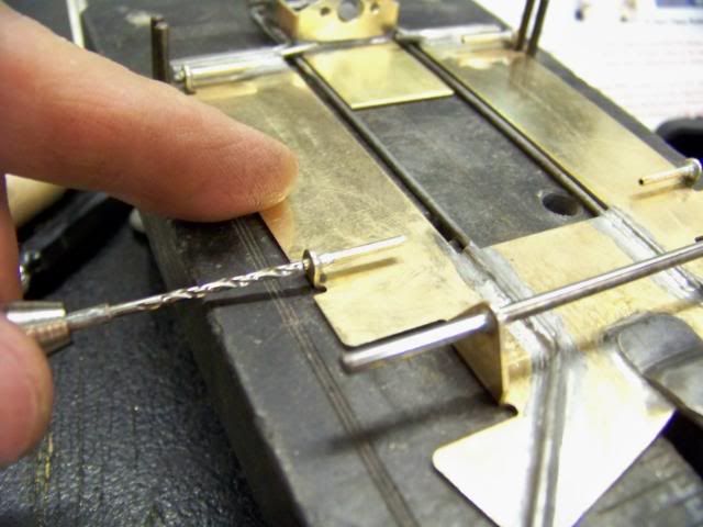
Shown is the 280 grit, which I prefer. It removes solder much quicker than the 180.
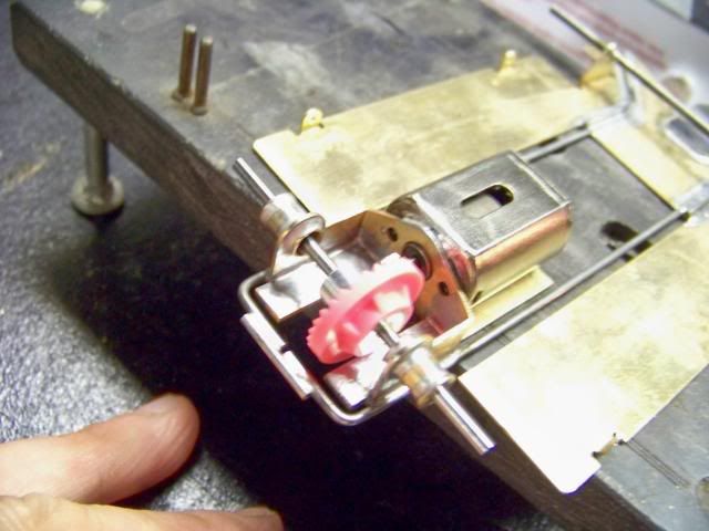
These also work great as an (almost) heat-free alternative to an iron for removing excess solder from any slot car motor can.
The level of finish is a matter of personal preference and won't affect track performance (assuming your solder joints have adequate integrity).
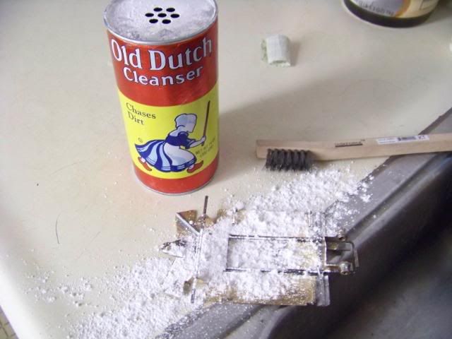
I prefer a chassis like "Sano" Dave Fiedler builds. Nice, strong joints but not afraid to show some solder. They may have as much as 5/16" of solder showing where he ran the whole width of the iron tip across the brass for maximum heat transfer. He cleans them up with just kitchen cleanser and a wire brush. IMHO, they look like a race car that will be run hard, which he obviously does.
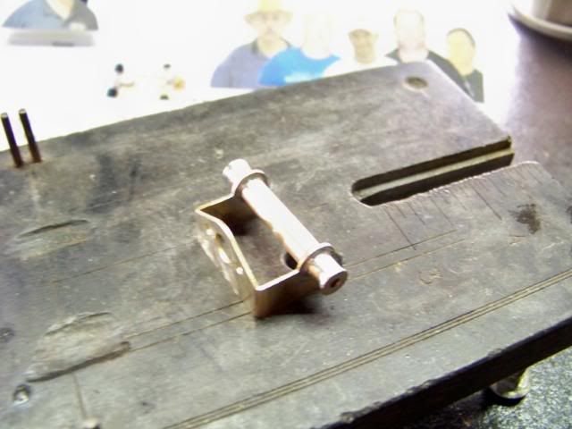
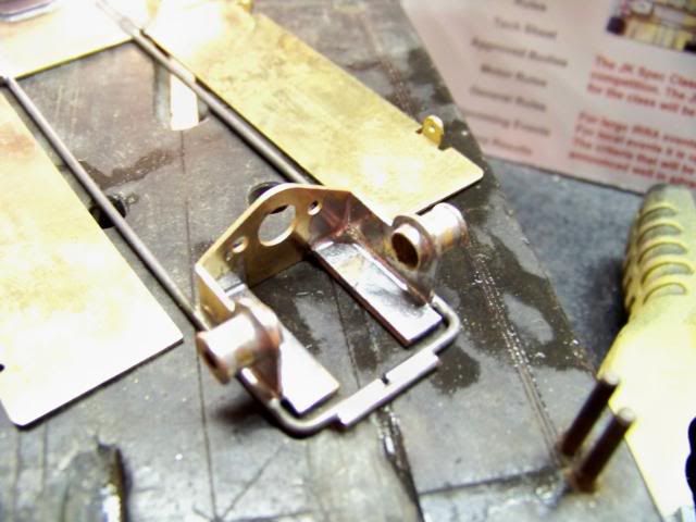
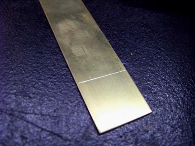
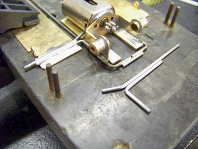
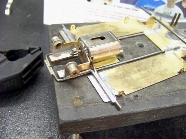
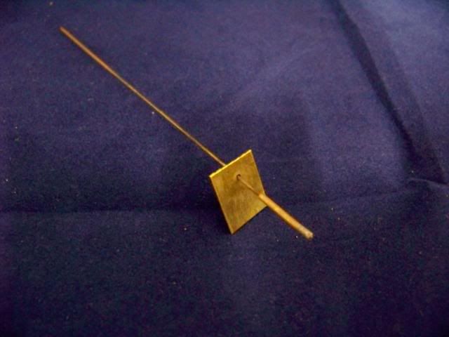
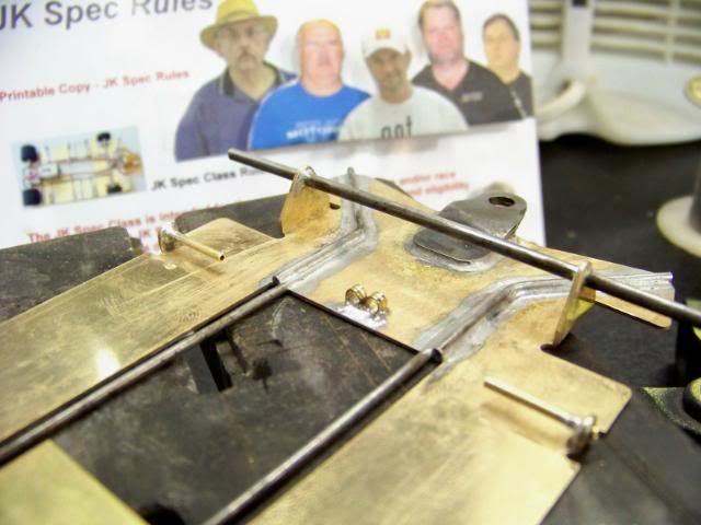
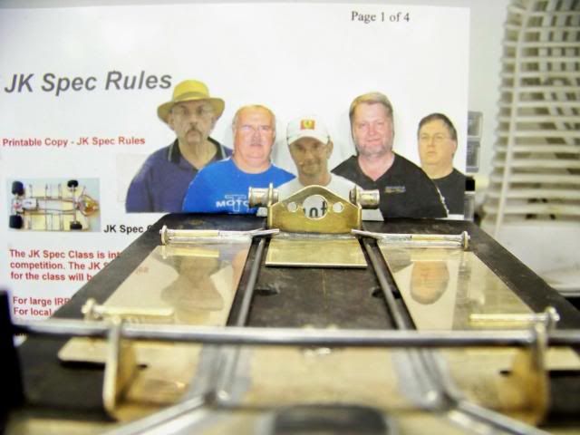
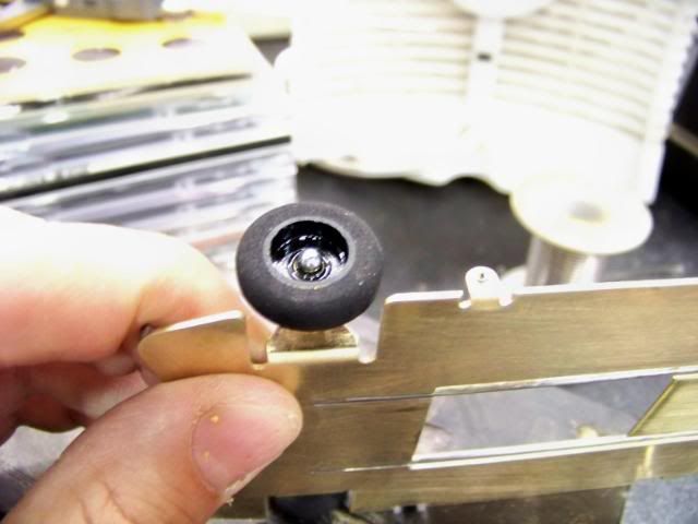
The other end of the spectrum are chassis that look like jewelry. Shown is one of the ear joints with about 10 seconds of polishing with the 511E buffs. I left a fair amount of solder on, but if you're willing to blow through a bunch of buffs, you can eventually make it appear like the wire was glued on (which would be weaker).
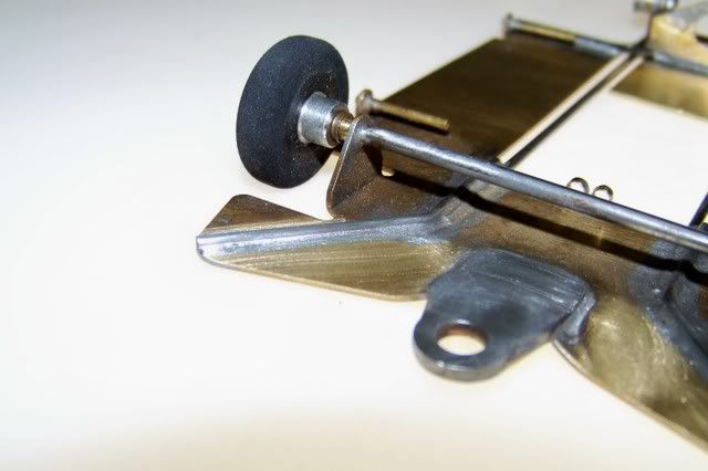
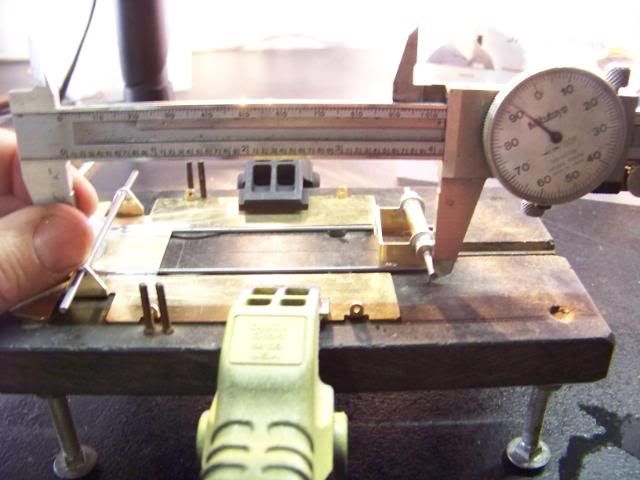
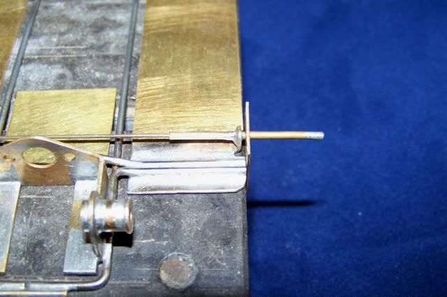
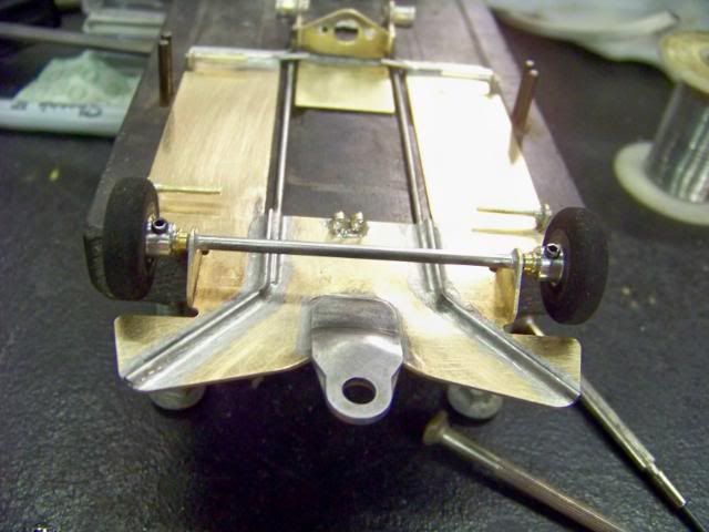
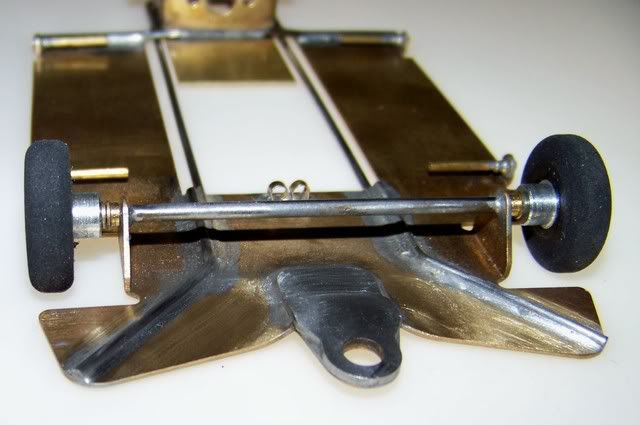
Another view with a little less glare. Uh oh, I notice a bit of rust in the middle of the axle. Before I go take care of it, I will warn you, that will be your typical trouble spot on Retro chassis. A long span of unplated, untinned steel that was at some point exposed to "Acid Flux Mayhem". (I think that was the name of the band that I saw open up for The Clash in 1979 )
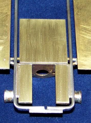
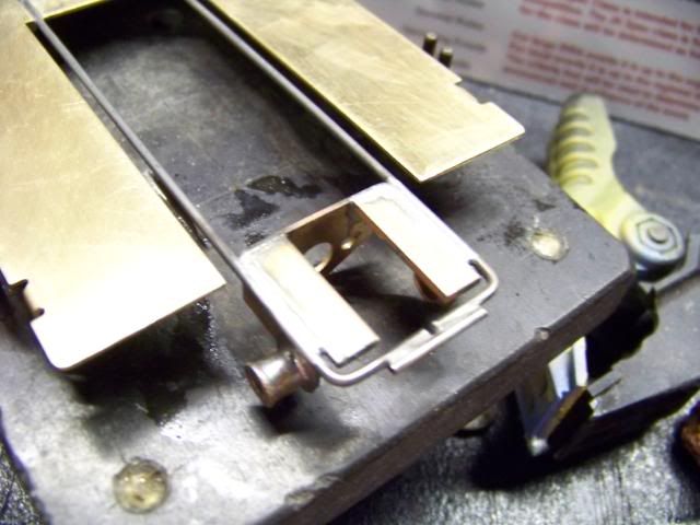
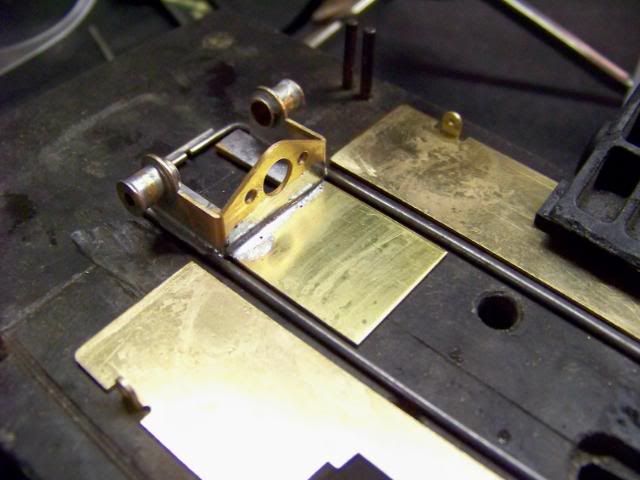
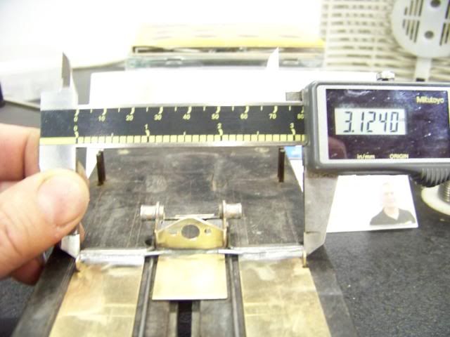
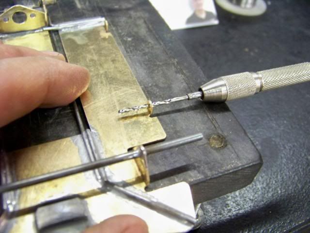
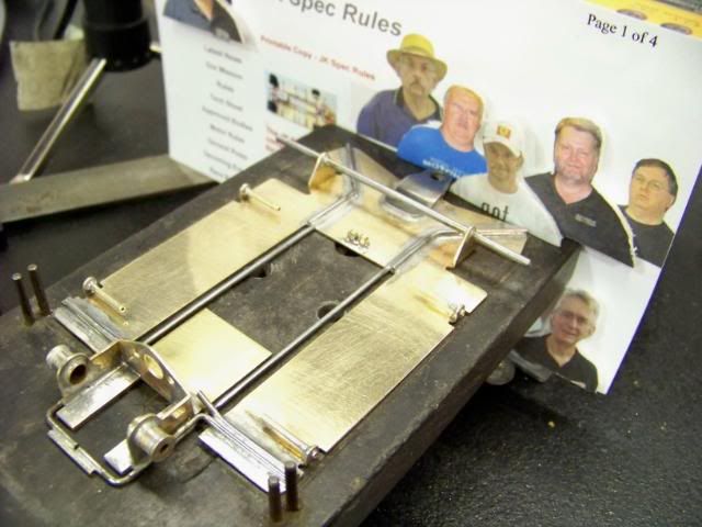
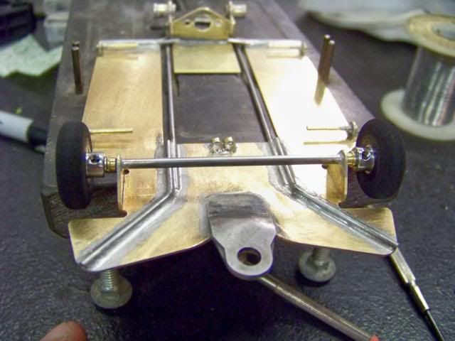
The weight/bracket area after a bit of buffing. Add 30-micron paper, a tumbler, and some polishing rouge and and "Mini-Greg Wells" of the IRRA Go7 could probably use it to shave.
#40
Posted 19 September 2008 - 08:37 PM
I finally finished the text. I also added a few more pics, rearranged them a bit, and added a long intro in post #1.
As noted there, this article was aimed at a novice builder, although one with medium experience might pick up a few things.
Your prolific Retro chassis builders like Tony P, Dennis S, Jim F, etc., probably won't learn a thing, but should feel free to add any comments that they feel would aid builders of all skills.
#41
Posted 21 September 2008 - 10:12 PM
Mike Swiss
Inventor of the Low CG guide flag 4/20/18
IRRA® Components Committee Chairman
Five-time USRA National Champion (two G7, one G27, two G7 Senior)
Two-time G7 World Champion (1988, 1990), eight G7 main appearances
Eight-time G7 King track single lap world record holder
17B West Ogden Ave., Westmont, IL 60559, (708) 203-8003, mikeswiss86@hotmail.com (also my PayPal address)
Note: Send all USPS packages and mail to: 692 Citadel Drive, Westmont, Illinois 60559
#42
Posted 21 September 2008 - 10:12 PM
So I guess I'll have to settle for Sano Dave and Ricky D.
Mike Swiss
Inventor of the Low CG guide flag 4/20/18
IRRA® Components Committee Chairman
Five-time USRA National Champion (two G7, one G27, two G7 Senior)
Two-time G7 World Champion (1988, 1990), eight G7 main appearances
Eight-time G7 King track single lap world record holder
17B West Ogden Ave., Westmont, IL 60559, (708) 203-8003, mikeswiss86@hotmail.com (also my PayPal address)
Note: Send all USPS packages and mail to: 692 Citadel Drive, Westmont, Illinois 60559
#43
Posted 21 September 2008 - 10:13 PM
We'll start fresh with any questions, comments or tips.
Mike Swiss
Inventor of the Low CG guide flag 4/20/18
IRRA® Components Committee Chairman
Five-time USRA National Champion (two G7, one G27, two G7 Senior)
Two-time G7 World Champion (1988, 1990), eight G7 main appearances
Eight-time G7 King track single lap world record holder
17B West Ogden Ave., Westmont, IL 60559, (708) 203-8003, mikeswiss86@hotmail.com (also my PayPal address)
Note: Send all USPS packages and mail to: 692 Citadel Drive, Westmont, Illinois 60559
#44
Posted 21 September 2008 - 10:29 PM
He use an approximately .500" long piece of 1/8" square brass tubing soldered on the outside of the main rail in the area along side the motor bracket. He then solders two simple .047 wire L's on the back of each pan. The inside of the brass square acts as the downstop/sidestop/upstop.
As I've stressed in all my posts as being all-important, the leg of the L that is inside the square, is pushed all the way to the inside, before the other leg is soldered to the pan. This is to eliminate any perceivable side movement.
Mike Swiss
Inventor of the Low CG guide flag 4/20/18
IRRA® Components Committee Chairman
Five-time USRA National Champion (two G7, one G27, two G7 Senior)
Two-time G7 World Champion (1988, 1990), eight G7 main appearances
Eight-time G7 King track single lap world record holder
17B West Ogden Ave., Westmont, IL 60559, (708) 203-8003, mikeswiss86@hotmail.com (also my PayPal address)
Note: Send all USPS packages and mail to: 692 Citadel Drive, Westmont, Illinois 60559
#45
Posted 24 September 2008 - 10:41 AM
Andrew G. Kimbrough
former raceway owner
(812) 430-8818
#46
Posted 24 September 2008 - 12:44 PM
Thanks, Mike.
A_Flat_Track_JK_Spec_Chassis.pdf 1.63MB 320 downloads
Joe "Noose" Neumeister
Sometimes known as a serial despoiler of the clear purity of virgin Lexan bodies. Lexan is my canvas!
Noose Custom Painting - Since 1967
Chairman - IRRA® Body Committee - Roving IRRA® Tech Dude - "EVIL BUCKS Painter"
"Team Evil Bucks" Racer - 2016 Caribbean Retro Overall Champion
The only thing bad about Retro is admitting that you remember doing it originally.
#47
Posted 24 September 2008 - 02:03 PM
Mike,As I've mentioned in some of my race results, "Sano" Dave Fiedler has built a JK torsion-style chassis of his own. He has been tearing up the flat track with it. His version is quite similar to the one in my how-to article. The main difference, along with using the JK hypoid bracket, is his downstop/sidestop/upstop set-up in the back of the car.
He use an approximately .500" long piece of 1/8" square brass tubing soldered on the outside of the main rail in the area along side the motor bracket. He then solders two simple .047 wire L's on the back of each pan. The inside of the brass square acts as the downstop/sidestop/upstop.
As I've stressed in all my posts as being all-important, the leg of the L that is inside the square, is pushed all the way to the inside, before the other leg is soldered to the pan. This is to eliminate any perceivable side movement.
Very interesting.
I liked your article and I wanted to try and build another JK Spec chassis. This one was going to be a 'torsional' one as you built. I did not get a warm fuzzy feeling with your method of securing the pans. I came up with the same solution as Sano Dave. I've yet to try it, but it sure looks like it will work.
About the only 'issue' I see with the build is that now I'm going to have to add some weight just to make it to 110 grams.
Oh well, I can put the weight right where I want it.
Thanks once again for a fine article. And ya gotta love all those pictures.
I hope to let you know mine is tearing up all sorts of tracks as well.
1/24/48-2/18/16
Requiescat in Pace
#48
Posted 24 September 2008 - 06:39 PM
#49
Posted 24 September 2008 - 07:21 PM
I do not know where Sano Dave mounted his.
This is a photo of the way I did mine.
Hope this helps.
1/24/48-2/18/16
Requiescat in Pace
#50
Posted 24 September 2008 - 07:34 PM