


After Martin and I finished the MDC Bat car chassis, we were thinking it would be fun to create a 3D printed version of a vintage chassis design that was a bit more performant. The Bat car is fun in that it really invokes the spirit of the original design but being a hard body car with a high center of gravity, it’s never going to be winning the local Saturday night races. This is when Martin introduced me to Tony P’s drop dead gorgeous Starship. For those not familiar with this chassis, here is a build by Rick Thigpen in which he makes his own Starship (thanks Rick): https://slotblog.net...ip/?hl=starship. Now for a big caveat: Martin thought it would be cool if we could make our’s a sidewinder. And from my tuning fork sidewinder (https://slotblog.net...ork-sidewinder/), I knew a sidewinder with a modern minican motor could have tires as small as 7/8”. With this in mind, we laid out the basic parameters for our Starship:
- Minican sidewinder.
- 3 1/8” chassis width.
- 3 7/8” wheelbase.
- 7/8” guide lead.
- 7/8” rear tires. This mandates a 3/32” axle for clearance.
- .050 clearance under the rear.
- 3/4” front tires.
- .015 clearance under the front.
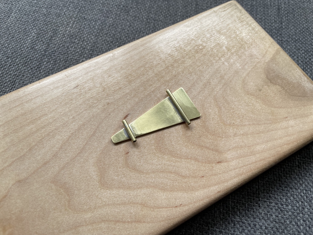
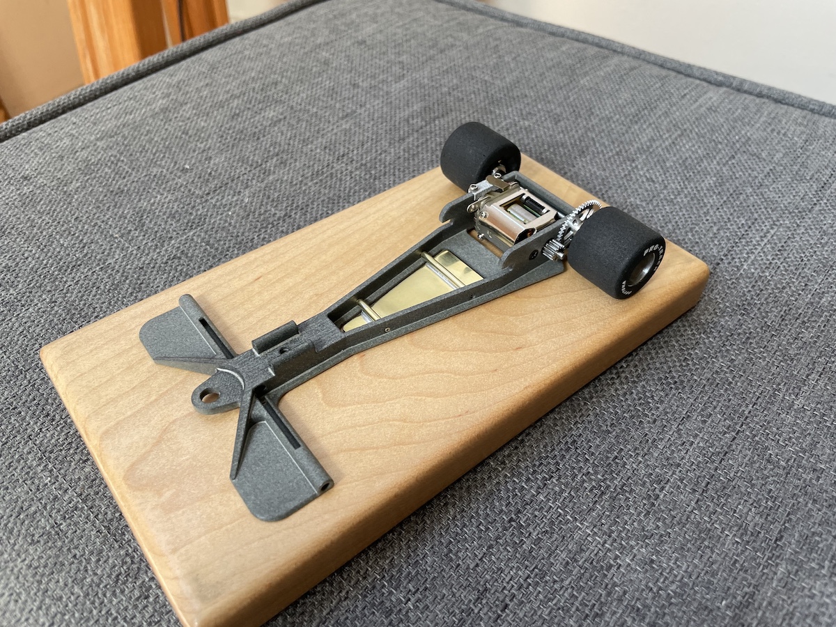
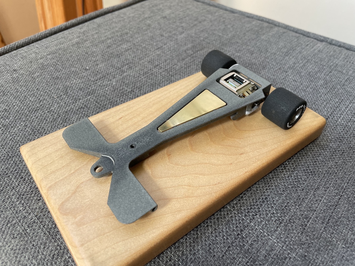
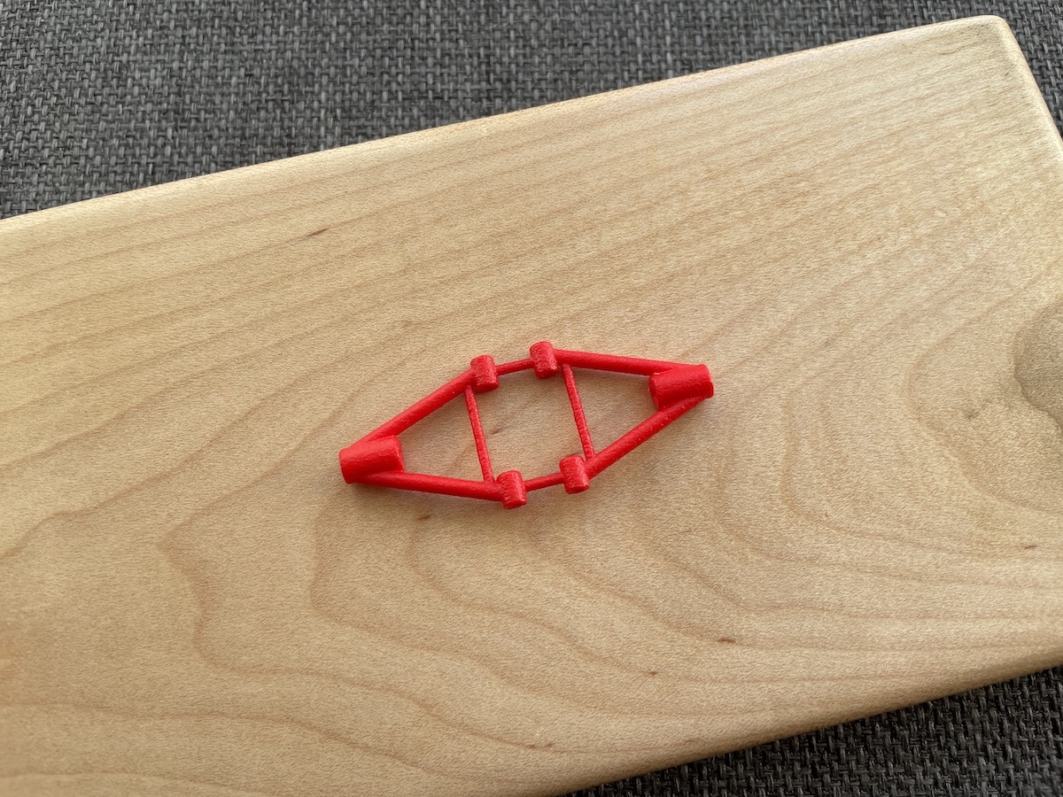
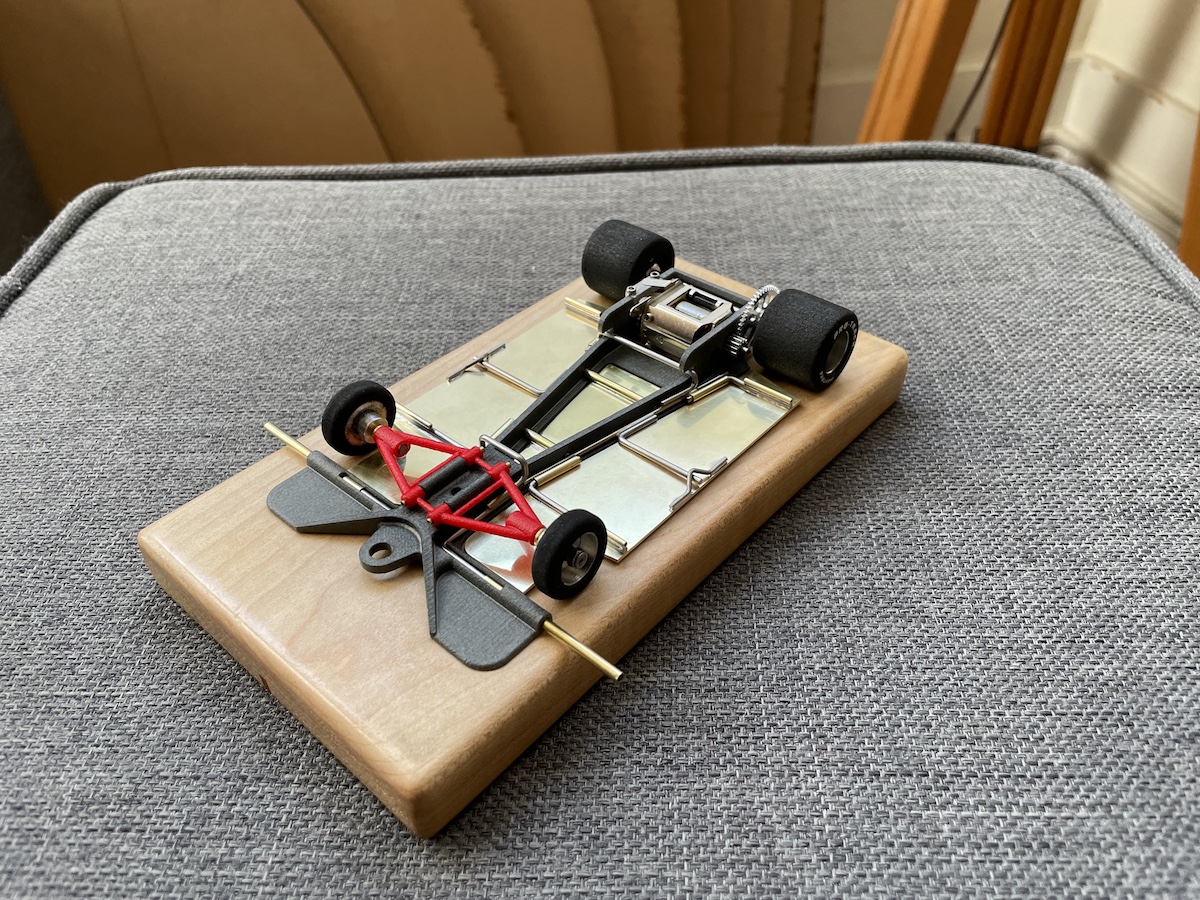
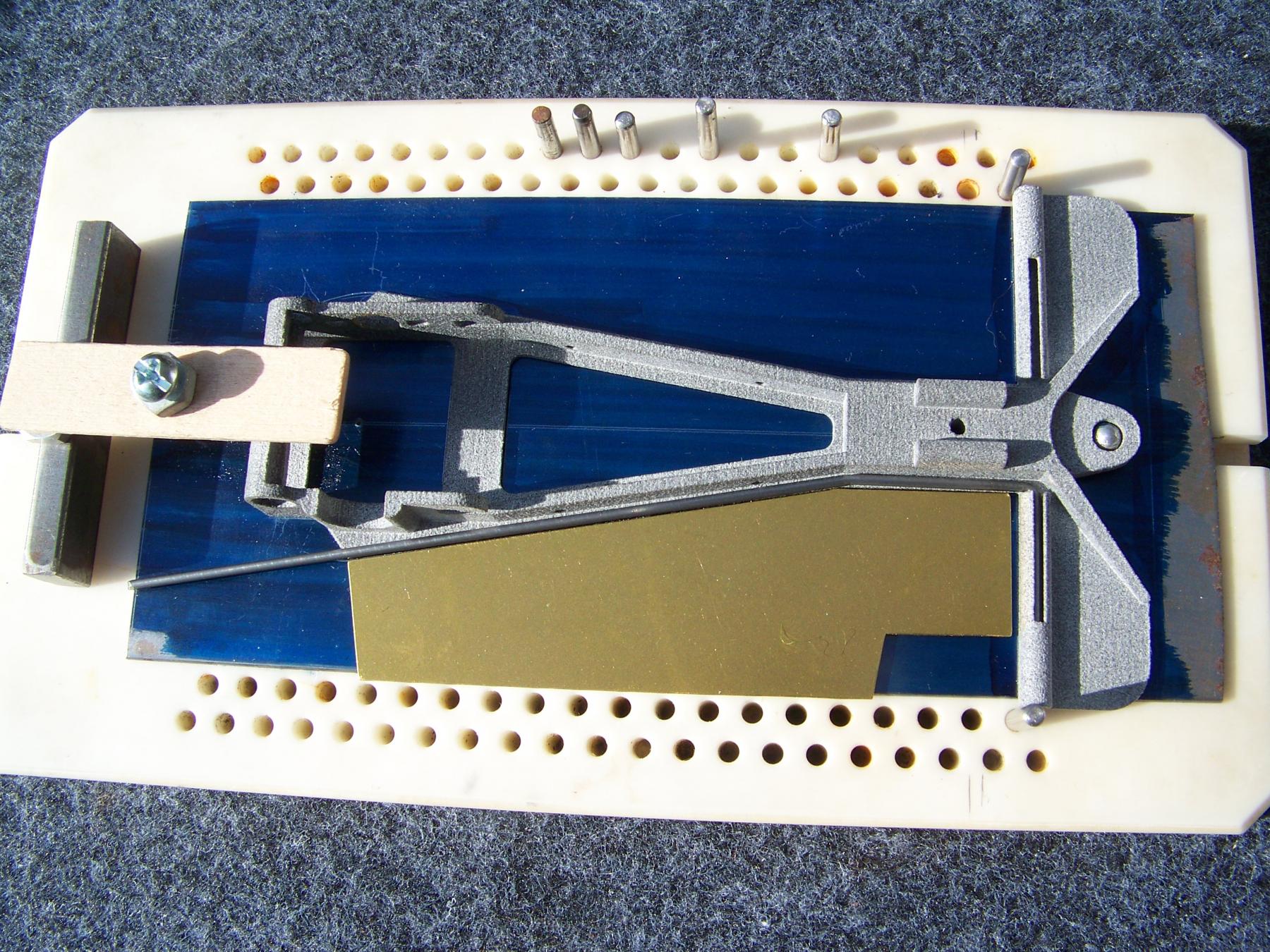
Another factor that influenced our design is that I knew we would be using SendCutSend for the custom cut brass pieces and they won’t cut anything thinner than .040”. And curiously, when 3D printing in PA12 nylon reinforced plastic, the minimum recommended thickness is also .040”. So Martin suggested a design in which our plumber rail would ride on top of a .040” printed lip that would blend perfectly with the brass pans along the seams. You can probably see where this is going but while PA12 plastic can take temps over 400 degrees Fahrenheit, it definitely can’t take the heat of soldering. So our Starship required a design in which the plumber rails, hinges and pans could be fabricated separately and then dropped into the plastic main section … what could possibly go wrong? Once the basic concept had been formulated, Martin started working on design sketches and this is where his talents far outshine my own … I’m a fabricator but not an artist!
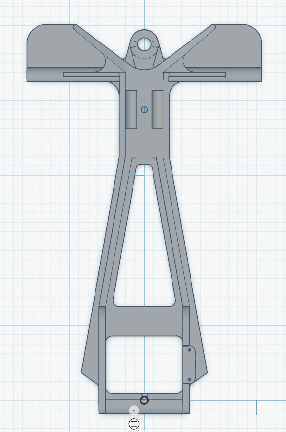
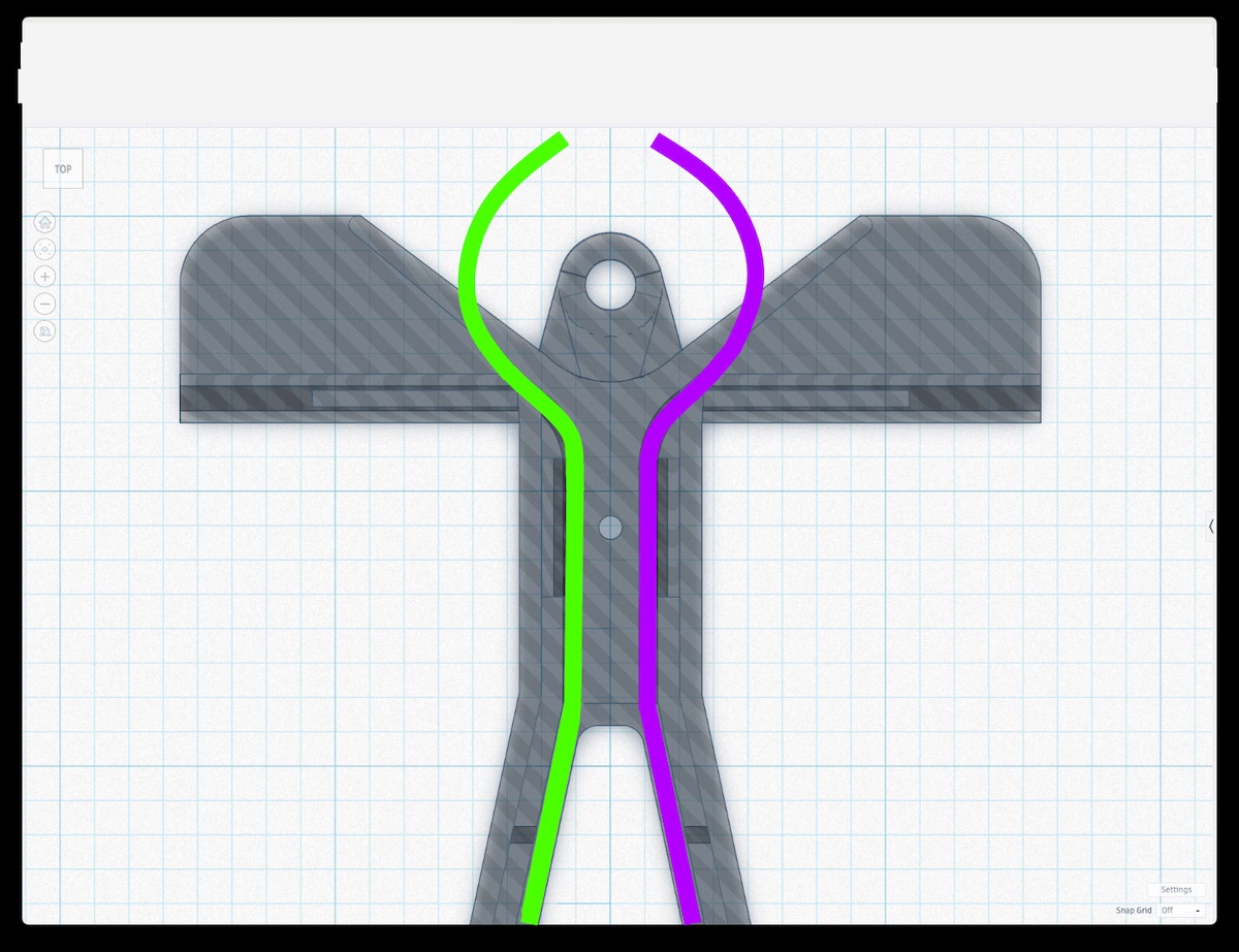
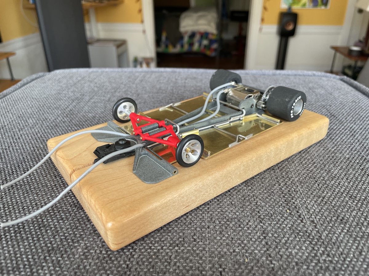
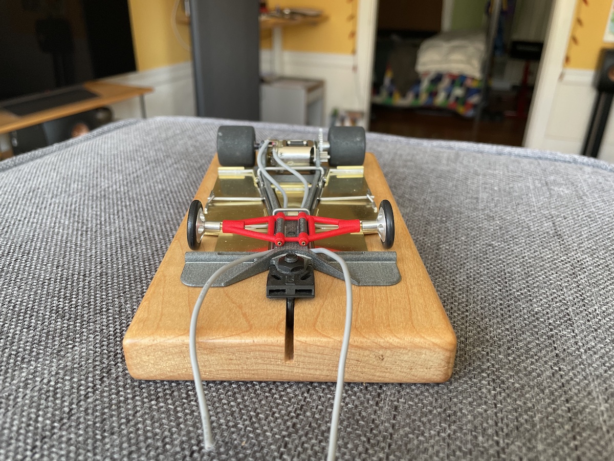
After several design iterations and printed prototypes, we thought we were close to the goal line when I accidentally dropped a prototype with installed drivetrain on my hardwood floor only to have one of the leading wingtips break off … nicht sehr gut. So it was back to the drawing board and lots of additional gusseting was added for additional frontend support. I might add that the original Starship had a 24 degree included angle at the back while this one is only 20 degrees. We could have used 24 degrees but when we tried that, the motor ended up skewed off to one side losing the symmetry that I think is one of the strongpoints of this design. The raw chassis is 11 grams and something not obvious here is that the guide tongue extends forward at a 2 degree angle as is commonplace in today’s vintage racing. So without further ado, here is a CAD drawing and 3D print of the final design and I think you can see why I’m calling it the Burning Man Starship!
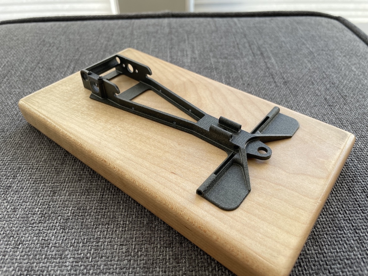
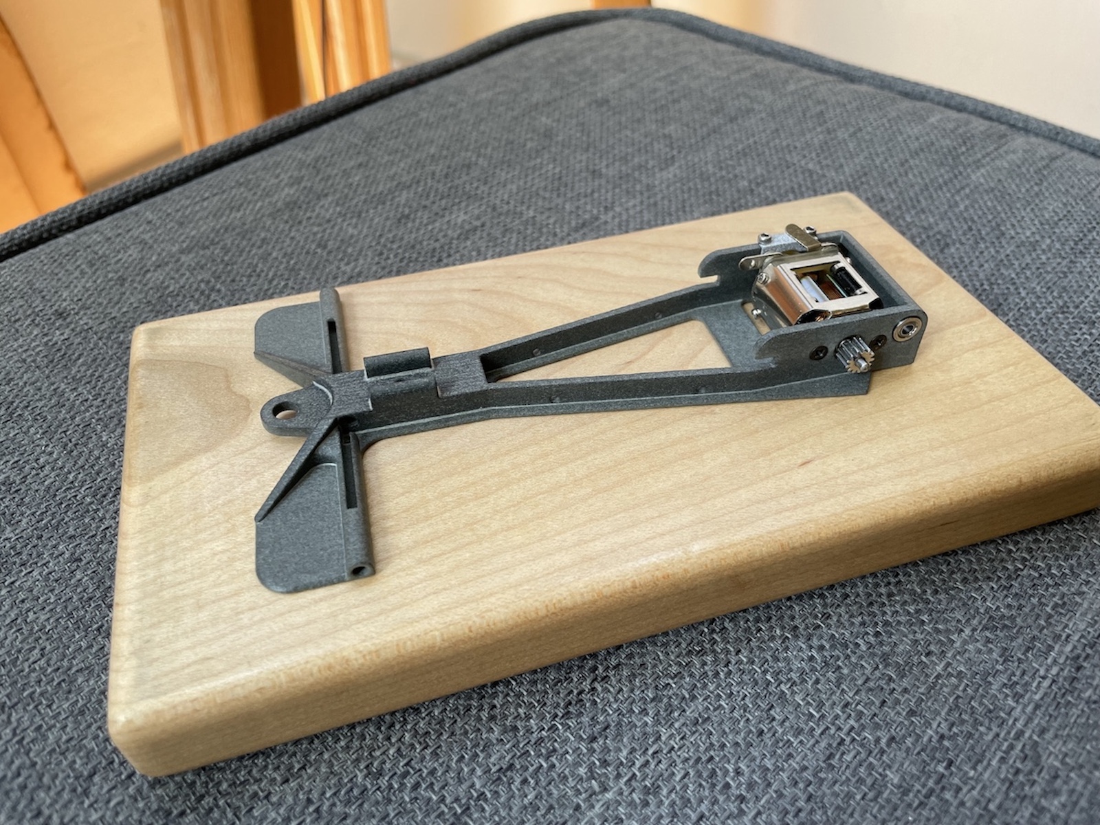
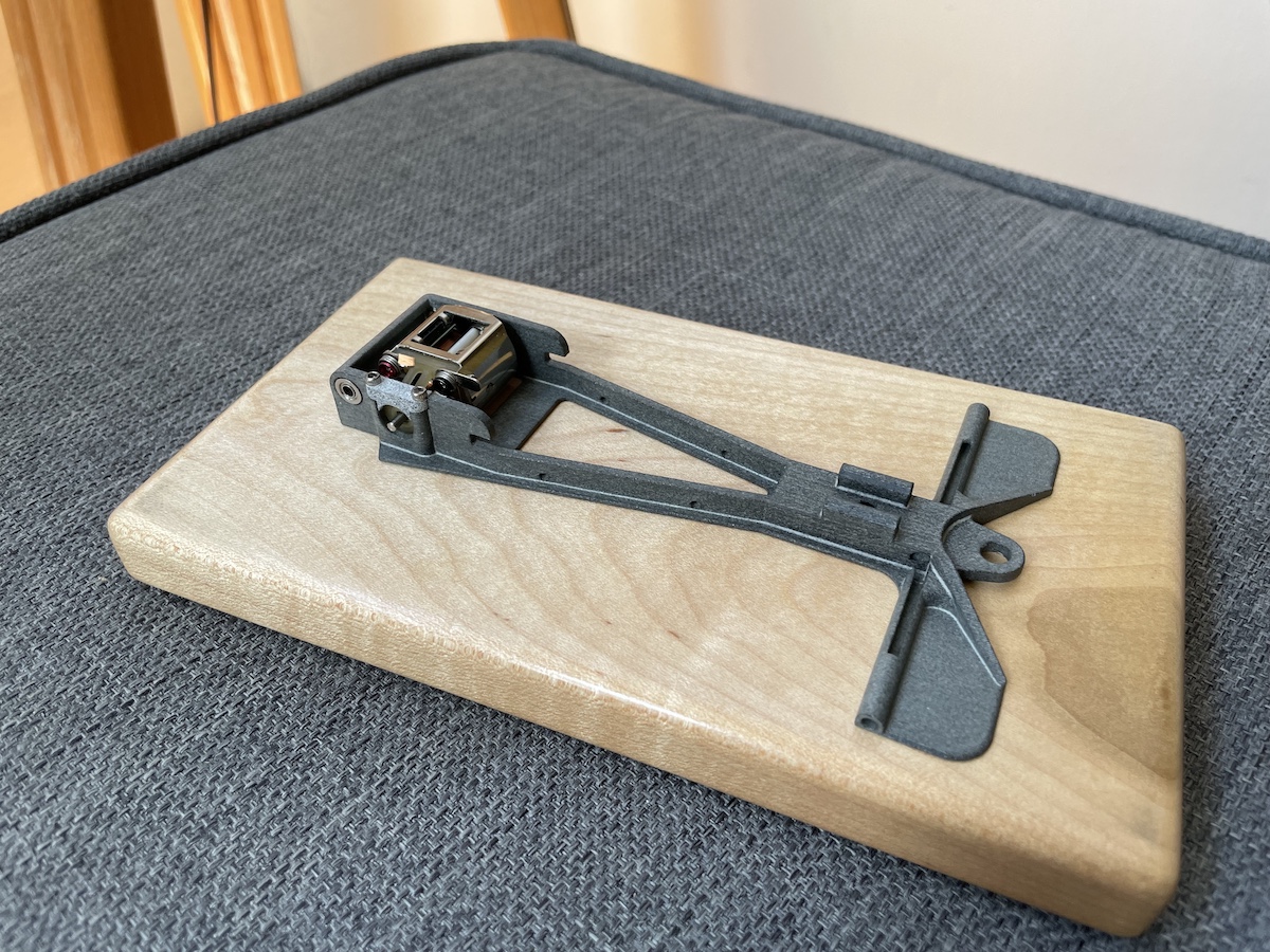
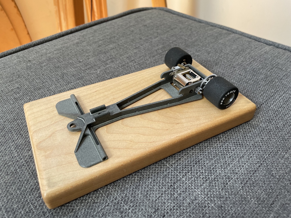
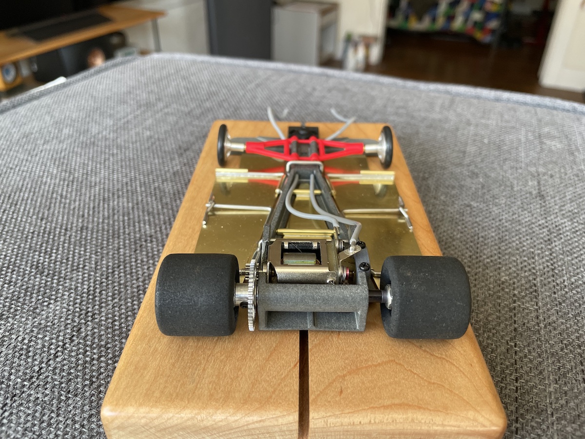
Here is a shot of the printed main chassis with a JK Hawk 6 motor mounted. We designed around this motor mostly because its tapered end-bell allows the motor to be “angled” in between the sidewalls of the motor-box. But additionally, there are lots of aftermarket arms if someone wants more poke. And since we opted for a predefined 12/48 gearing, the motor is solidly locked into position with flat head 2mm screws. Not only does this provide very secure and accurate positioning of the motor but the flush heads allow the spur gear to run inboard.




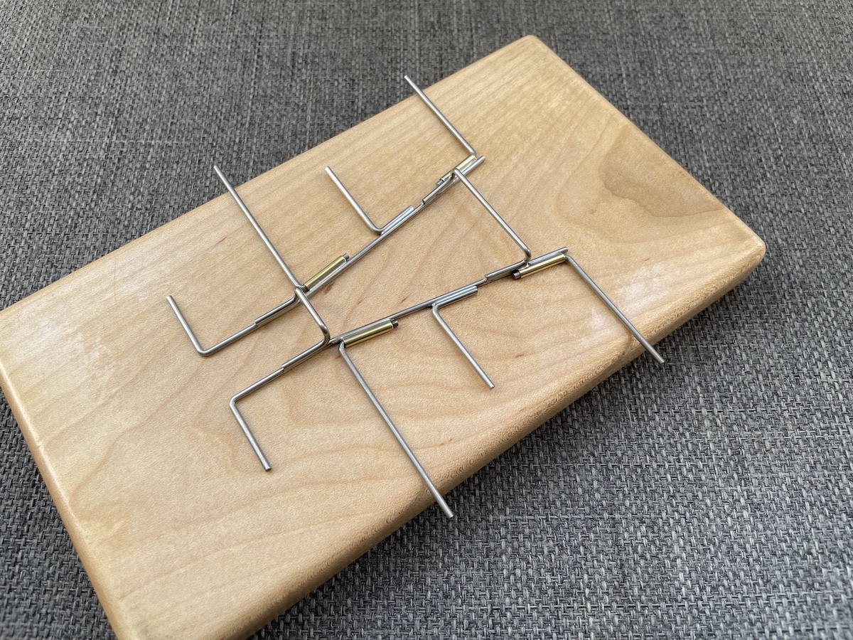
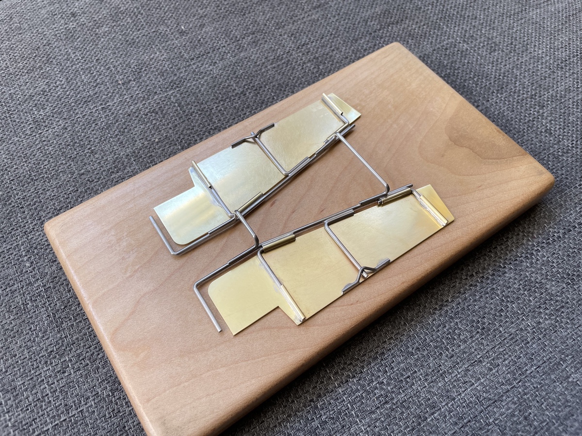
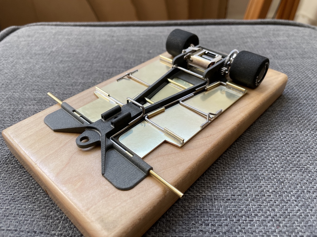
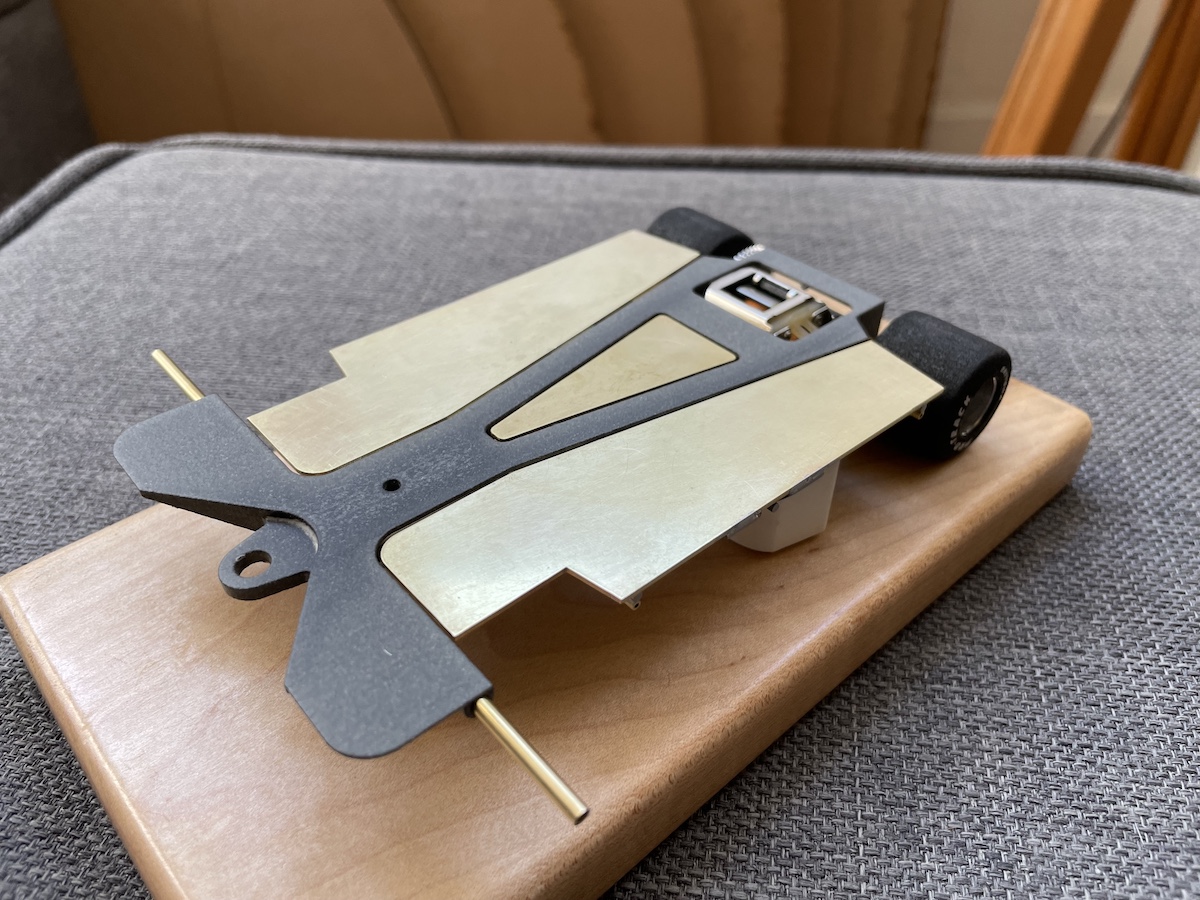


 But in answer to your question, my Shapeway's shipment is in route so hopefully I will have the new chassis in hand in the next couple of days. The real problem is that my closest track (since Eddie's closed) is now a couple of hours drive away although I do admit that I've never been to the Modesto track and am looking forward to seeing their hillclimb.
 Happy days.




