1966 Team Russkit 26D racer
#1
Posted 29 October 2011 - 05:59 PM
Team Russkit McLaren MkII
It turns out that not only did Team Russkit member Fred Larimer build a racer with the Russkit McLaren Mk II body, he powered it with the then new Mabuchi 26D. The details of his car are in Tom's post.
Here's Fred at the second Rod & Custom race in 1966. He's on the far right...
... after taking placing second in the Concours with his Porsche Carrera 6 shown on the bottom:
Here he is again at the third R&C race qualifying his Lotus 25 GP...
......that's his second place concours winning Lotus on the bottom:
I've been itching to build a 26D R&C racer. I've built Fred's 16D-powered GP Lotus 25...
1966 Rod & Custom Lotus GP
... and Mike Morrissey's Lotus 40 sports car:
1966 Rod & Custom Race winner
Here are the parts I've set aside for this project. K&B hard vinyl front tires, VC rear grey donuts and Russkit repop front and Xtra wide rear wheels:
Small Russkit Slant Guide, Lenz braid, and Cox Superflex lead wires:
Russkit motor bracket, French 7T pinion, and either a Cox Nylatron or Weldun aluminum crown gear:
Next, some body and motor decisions need to be made...
Rick Thigpen
Check out Steve Okeefe's great web site at its new home here at Slotblog:
The Independent Scratchbuilder
There's much more to come...
#2
Posted 30 October 2011 - 10:26 AM
I'll be watching this build as that car and Mike was the killer package! I love the 40 and that's all I use on my Jail Doors!
If you need a Cox gear I may have one...
Barney Poynor
12/26/51-1/31/22
Requiescat in Pace
#3
Posted 30 October 2011 - 11:19 AM
I am well aware of these pictures, but they are hardly re-printable on paper. I was looking for a real photo that could be scanned in hi-res for the book...
Looking forward as usual to watch your next amazing build.
Philippe de Lespinay
#4
Posted 30 October 2011 - 12:16 PM
Thanks for the offer of a Cox gear. I have some but I'm undecided if I should use it or the Weldun aluminum gear lots of guys ran in the sixth and final R&C race. Everyone in the main at that race used the Cox quick change guide too...even Team Russkit. Hmmmm......
Hi Philippe,
I just thought it would be fun to show fellow bloggers pictures of Team Russkit's Fred "Ken" Larimer racing back in 1966 . I think the one of him standing alone at the control panel, qualifying his little Lotus GP car on that huge track is cool .
So it's motor time. Here's the 1967 Russkit Catalog front page (mine's a photo copy, the original is in beautiful color).....
....and the Russkit 26 motor. As Philippe said, it was most likely never sold. But I have seen them listed in distributor ads in the old magazines:
Anywho, Fred says his motor used a green wire rewind (can't wait to see the pics Fred, thanks!). I dug around in my Box-O-26D's and found 2 green wire rewinds . Both look pretty sad however .
The first on appears to be a Dynamic Green Hornet parallel wound armature:
The arm was "blown". The solder was all blown off the comm tabs and one set of parallel wires was blown off the tab. I wound the wires back around the tab and soldered all 3 comm tabs....now the thing runs . In fact it screams :
I cleaned it all up and polished the comm. Look how little wire is wound on that arm. You can see the laminations between each poles windings :
I even repainted the colors on the back of the windings and squared up the brass spacer with a diamond tool:
The other green wire rewind look to be a home made job. Check out the comm timing, it must have 50 degrees of advance :
I had to resolder the wires onto its Tradeship comm and clean up all the rust. Unfortunately, somewhere in the process a chunk fell off one segment at the front of the comm . I glued on a new fiber washer and filled the void up with 2-ton epoxy:
This thing REALLY screams when buzzed up. And speaking of "buzzing", it's WAY out of balance.
So there are my "green wire" armature options. I think I'll just have to build a 26D setup and try out the different arms on my home track. I won't be able to stretch their legs on my little track but I can tell if they have any brakes and see if they start getting hot and "stinking".
The 26D setup is next.....
Rick Thigpen
Check out Steve Okeefe's great web site at its new home here at Slotblog:
The Independent Scratchbuilder
There's much more to come...
#5
Posted 30 October 2011 - 01:29 PM
First, one has to know that all Mabuchi factory FT26 motors were originally wound with BLUE wire, but over time and with a bit of heat into it, it turns green. The only arms I am aware wound with green wire were made by Igarashi for Strombecker and Pactra.
The Dynamic Green Hornet was a stock arm with 10 turns removed from each pole, then High-Temp varnish applied, which turned its color to green. These were produced for Dynamic by Ron Mura and his crew in San Leandro.
The other you got is definitely a home made job and a definite grenade awaiting explosion with that big fat wire!
This Green Hornet above has not seen any heat, so is still blue. Give it a few laps on 13 volts and it will turn green.
If you do not have a clean FT26 can/endbell for the project, please PM me.
Philippe de Lespinay
#6
Posted 30 October 2011 - 04:08 PM
Looks a bit like that first arm of yours Rick, but with red wire. Don't have a better photo of the motor on tap, but here it is in the chassis - and it's under a McLaren!
Don
#7
Posted 30 October 2011 - 04:50 PM
Don, it was later rewound by the owner, likely after the arm failed as they often (always?) did. The Dynamic Green Hornet motors, I have seen enough of them by now to be sure that the only ones that were rewound were the FT16D "Green Hornet II" found in the Dynamic Super Bandit RTR models and the original FT36 Green Hornet that was a standard Russkit "33" repainted in green and rewound with the bright red wire also used on the GH II.Hmmm, I've got a Dynamic 26D Green Hornet mounted in a scratch-built car that was probably built in England and it definitely seems to have been rewound, with red wire -
The GH FT26 arm was dewound (10 turns), the wire ends re-soldered to the comm, the stack was never polished, just coated with the HT varnish, then balanced with a sheet-metal "flat" drill. The ones that have a polished stack, the customer did that himself, much like the Champion 507 and 517 armatures found today with a polished stack that Champion NEVER polished.
Here are two pics of two GH II:
And one of the original GH (using the 1964 early FT36 without the heat sinks on the brushes). This one DID have a machined stack.
The FT26 Green Hornets were always a "dewind" motor from the works, never a "rewind".
Philippe de Lespinay
#8
Posted 30 October 2011 - 06:51 PM
The GH FT26 arm was dewound (10 turns), the wire ends re-soldered to the comm, the stack was never polished, just coated with the HT varnish, then balanced with a sheet-metal "flat" drill.
That describes my armature exactly. Since I seem to have a real live Dynamic Green Hornet motor I'd like to restore it back to stock condition for a Dynamic, not Russkit project.
For this project I believe I should use an early rewound 26D. A pre-welded comm, pre-ARCO magnet 26D if you will. That leaves me with the "Green-Grenade" and another red wire arm I found:
I started with this motor for my 26D setup:
I cleaned and polished everything up, replaced the brushes and springs, drilled and tapped the endbell for machine screws, attached the endbell to the can with screws and shimmed the stock magnets to a .010" air gap per side:
Here's the "Green Grenade" ready to roll..... ....or explode :
It vibrates a lot less since I static balanced the arm but it draws a good 2 amps at 3 volts and gets hot after a few minutes. Hmmmm....maybe it's a qualifying motor . It doesn't have to go race distance. It just needs to be the torque monster that Fred remembered his to be for a few laps at a time.
Kind of like bringing the dead back to life again....perfect for halloween!
Rick Thigpen
Check out Steve Okeefe's great web site at its new home here at Slotblog:
The Independent Scratchbuilder
There's much more to come...
#9
Posted 30 October 2011 - 06:59 PM
Tradeship had plenty of pretty good FT26 arms, wound in Japan, shipped to San Francisco and balanced on Freddy Foyn's dynamic balancer that did all the arms around San Francisco until Ron Mura bought one in 1968 at the insistence of John Cukras...
I think that the "red" arm you have might be one.
Philippe de Lespinay
#10
Posted 30 October 2011 - 09:41 PM
The stock 26D motors were actually pretty well balanced. Magnets matched the wind, endbells usually held up, and the very cheap ball bearings held up. With even a mild rewind, 55/28, the endbell bearing would spin or the endbell melt.
At $3.29 the stock version had good value. If you wanted speed better buy a 617 that had the goodies.
11/6/54-2/13/18
Requiescat in Pace
#11
Posted 30 October 2011 - 10:32 PM
FWIW -
Looking at the photos from the 2nd R&C race - the one with the 4 cars crashed - I think that is BG's car in the lane, over to the right, and pretty clearly, my 906 with the white stripe across the nose, still in the slot about dead center in the photo (Al was pretty good with a camera!).
Recall that us Russkit-er's usually used Russkit "orange" for our car colors. In our pre-race practice sessions it quickly became obvious that you could lose our car amongst all the orange cars which is why I opted to change the color of my car's body and added the white stripe across the nose. Made it much easier to spot.
More FWIW - the J&J's race - the car I raced - and that Rick reproduced (lovely I might add) - the gearset that I ran for that event - I remember John C and Pete Z checking in with me after qualifying, letting me know that I was running out of revs - using too low a gear - before the sweeper at the end of the straight. Wasn't so bad for single-car qualifying but surely did cost me time. Given I used the car at subsequent races I did change the gearing. Yeah, as Gene reported, stepping up there to qualify in front of everyone, especially your competitors, was nail-biting. All of us were competitive and could easily determine what the other racer was - or wasn't - doing, but we also were each other's "cheerleaders".
Darned proud to have been part of that and can tell you how much fun we all had with one another and at one another's expense. What a great group of folks let me tell you.
FLarimer & Associates
Software Consulting
#12
Posted 31 October 2011 - 05:15 PM
Red Wire, Brown Comm insulation (standard type/non-Kirkwood), double ended shaft, Unbalanced 26D arm ?
It looks like a "production" wound piece. If I can dig it up I'll post a picture.
Bob Israelite
#13
Posted 31 October 2011 - 06:23 PM
I intend to live forever! So far, so good.
#14
Posted 01 November 2011 - 08:11 PM
Please do, but it is not Mabuchi themselves. Possibly an unfinished rewind by???anyone know who may have made a:
Red Wire, Brown Comm insulation (standard type/non-Kirkwood), double ended shaft, Unbalanced 26D arm ?
It looks like a "production" wound piece. If I can dig it up I'll post a picture.
OK, Fred stopped by today and showed me his "26D" car. First, it survived in modified, open-wheel form and not as the sports car it used to be, as Fred younger brother modified it after Fred left for the Air Force in mid 1967.
The car apparently had some encounters with some hard walls as it shows rather hastily performed repairs, probably done on the spot to keep racing. But the motor is still there and wears a gold Russkit decal. But guess what? The motor was obviously opened at one stage, no longer has its stock arm, and was modified more than once as there are various added endbell-mounting holes on the can. The armature is now the same as that of the Dynamic Green Hornet (and likely IS one), meaning a de-wound, blue-wire (not green really), with its stack not machined, and coated with HT varnish and balanced afterwards. A bit of the silver paint used to make one of the poles for dynamic balancing has sprayed on the stack in one location.
I am sending the pictures I took to Rick, and Rick will decide on what to do with them.
Philippe de Lespinay
#15
Posted 02 November 2011 - 12:54 AM
Dok feels the car could be restored to it's former self without out too much work. I think it might be better to build a replica and leave the original as is. Hmmmm...maybe I need to get one of these jigs like Rick has and dust of the Weller...
FLarimer & Associates
Software Consulting
#16
Posted 02 November 2011 - 09:36 AM
Hmmmm...maybe I need to get one of these jigs like Rick has and dust of the Weller...
You should Fred! I bet you'd have a blast
.......But guess what? The motor was obviously opened at one stage, no longer has its stock arm, and was modified more than once as there are various added endbell-mounting holes on the can......
Stock or rewind......
Fred, do you think Mike have given you a stock motor to try? Toward the end of the R&C series the 16D rewinds were getting pretty stout with 28 ga wire. I wonder if a stock 26D would have seemed like the "torque monster" you remember?
What do you think Fred?
I am sending the pictures I took to Rick, and Rick will decide on what to do with them.
Thank you Philippe. I'll post them here. Do you still have my email address?
Rick Thigpen
Check out Steve Okeefe's great web site at its new home here at Slotblog:
The Independent Scratchbuilder
There's much more to come...
#17
Posted 02 November 2011 - 11:11 AM
I intend to live forever! So far, so good.
#19
Posted 02 November 2011 - 12:33 PM
The motor - well, anything is possible.
That said, what I can relate -
The motor is pretty much as I remember it when I first received it from Mike M. I have no info on it prior to that point. Was it a "stock" motor? In my opinion it was some sort of special that Jim R et al were considering for the Russkit product line - mostly because my recollection from running the car/motor was that it was fast - equally as fast as the "23" rewinds that I had in my box. It would not suprise me at all if it was as PdL describes - a blue-wire that has since turned to green color insulation.
There is a period of time after I left the scene in August 1967 until the box was returned to me by my sons where anything could have happened to the motor. I will say that my brother wasn't one that would normally have opened it up and swapped in another arm, more than likely he ran it as it was and left it in the box when his interests went elsewhere.
I know that really doesn't help to answer the questions - and perhaps only raises more....
The Russkit jig - that would be the period correct thing to do... But, I do really like the one Rick is using as it is accurate and square...
Maybe the old guy in PdL's photo will see it fit to provide me with a gift for Christmas... <lol>
Cheers,
fL
FLarimer & Associates
Software Consulting
#20
Posted 02 November 2011 - 09:14 PM
The Russkit jig - that would be the period correct thing to do... But, I do really like the one Rick is using as it is accurate and square...
Maybe the old guy in PdL's photo will see it fit to provide me with a gift for Christmas... <lol>
Cheers,
fL
Hi Fred,
You can't go wrong with one of Rick's excellent chassis jigs. It really makes building FUN!
Philippe,
Thanks for the pictures of what's left of the surviror. Here they are:
It looks like at least 1 of the 1/16" brass rails is tube. The gentle bends are also very "tube like". I like that look .
Now the motor. I'm thinking I might put in the dewound arm I showed in my motor as it really matches the arm in this car:
Hmmmmm.....I think I'll try both arms in my setup. Maybe one will blow and decide the issue .
Anywho, thanks Fred and Philippe. I'm "a build'n"
Rick Thigpen
Check out Steve Okeefe's great web site at its new home here at Slotblog:
The Independent Scratchbuilder
There's much more to come...
#21
Posted 02 November 2011 - 10:05 PM
Philippe de Lespinay
#22
Posted 03 November 2011 - 08:42 PM
Something I'm wondering about Fred. Your original car seems to have all the main rails in front of the front axle tube instead of alternating front and rear. To my eye, so does Mikes car.
What do you think Fred?
PS Congrats on taking fastest lap!
Rick Thigpen
Check out Steve Okeefe's great web site at its new home here at Slotblog:
The Independent Scratchbuilder
There's much more to come...
#23
Posted 03 November 2011 - 09:27 PM
Anthony 'Tonyp' Przybylowicz
5/28/50-12/20/21
Requiescat in Pace
#24
Posted 03 November 2011 - 11:15 PM
Fred said he patterned his car after this one. I scanned the pic a 600 dpi but the original magazine photo is so small that I can only seem to enlarge it so far before all you see is a bunch of dots from the original :
Something I'm wondering about Fred. Your original car seems to have all the main rails in front of the front axle tube instead of alternating front and rear. To my eye, so does Mikes car.
What do you think Fred?
PS Congrats on taking fastest lap!
Rick - I retrieved my original chassis and touched a file to the end of the rails to see if I could determine were they tubing or rod.
The 3 original rails are indeed tubing.
And, yes, the chassis/car I borrowed from Mike was also tubing - as can be seen in the photos from the event. I would agree with your comment - on Mike's chassis the rails do all appear to come up in front of the front axle tube.
On the one I have the middle rail rises at about a 45 degree angle and is soldered to the bottom of the front axle tube. The (original) inboard and outboard rails are indeed in front of the front axle tube.
To my mind, this puts in question my memories of the car as I believed that I had built it using 1/16" rod (3 rails) with the 1/8" outboard rail (4th rail) being rod as well.
That leads me to one of two conclusions.
1. My memory is toast and the chassis I built was this 3-rail made using tubing.
2. My memory is toast and this is a different chassis altogether.
A couple of other thoughts wrt this particular chassis.
A. The MkII body would have had the normal 1/16" "pin" tube body mounts. I don't see any evidence of where these would have been soldered to the 3-rails (which supports conclusion #2).
B. the brass plate drop arm is definitely not what I would have used. The arm and hinge tube is not square to the rest of the tubes. Definitely not original to a car I would have built (which is in line with conclusion #1).
C. The "up" stop for the drop arm was added whenever this brass plate drop arm was installed. The "U" shaped brace is not tubing and was added in at a later point (which doesn't lend any support to either of my conclusions).
D. The front of the car appears to have been re-built - it is not square, there are small bits of what looks like thin piano-wire that are laced around the front axle tube and the 1/16" rails as some sort of reinforcement (again, doesn't support either of my conclusions).
E. The rear section of the car IS consistent with what I would have been building at that point in time (supports conclusion #1).
F. It does have a 26D style can.
What I am sure of at this point in time is: I have a old chassis that started life as a 3-rail, 1/16" tube chassis with a prototype Russkit 26D motor.
Wish my memory was more accurate and/or I had a picture of the car from back then...or my brother was still with us and I could ask him...
WRT fast lap. Thanks. The car "worked". Didn't chatter in the 360 that lead to the straight, I could drive it down the straight without having to lift for the dips and could keep it flat thru the banking. It was a great car to drive.
FWIW,
fL
FLarimer & Associates
Software Consulting
#25
Posted 06 November 2011 - 05:09 PM
So, here are some of your earlier quotes on your memories of your 26D sports car:
Rick -
The 26D can - for sure was some sort of a pre-prod example - I recall it was shiny silver - not Russkit gold - and the arm had green wire - no idea what it was but it had plenty of grunt.
The chassis I used was pretty standard for the time - working from distant memory so .. the regular Russkit rear mount with three 1/16" rod rails, I recall they were soldered together as they ran forward to the front axle tube. It seems to me that they were angled inboard slightly as they went forward. The 1/8" solid rods were outboard of the 1/16" rails (again, solid rod, not tubing) - spaced outboard by at least the width of the 1/8" rod and ran straight forward (not angled) to the front axle tube. I believe they were bent up at 90 degrees in front and at the rear about 60 degrees and - similar to the Lotus F-1 car - slightly canted so that where they soldered to the rear axle tubes they were almost all the way to the outboard ends of the tubes.
EDIT - where the 1/16" rods kicked upwards to the front axle tube, the center of the three was behind the axle tube and the inboard/outboard rods went forward of the axle tube. [end edit]
fL
Rick, PdL -
Rick - the chassis - yes, post R&C race 5 I borrowed the car from Mike so I could build a copy for myself. I'm not 100% sure if I put the 26D can in it from the beginning or if I retro-fitted it later on - as you can imagine we would build a car, try it, modify it, re-build it etc - at least for me, the cars were changing on a regular basis just like in real-life-racing.
Looking at the photo of the car I used at the R&C race, it appears at least some of the rails are tubing yet I recall that I used brass rod for the outboard rail - for strength and the extra weight.
All the best,
fL
I started by modifying the Russkit 23 bracket. I had a piece of a French 26D bracket left over from an earlier Thingie project....
....and I soldered it to the Russkit bracket and opened up the Russkit holes to match it:
Next came the rear axle bearings, or lack thereof. It kills me not to use ball bearings or at least oilite bearings for a rear axle. But these cars used brass tubing so for grins I decided to find out how sloppy the tube really is:
I used a "tenth" mic and a small hole gage to check the inside diameter of about 20 different pieces of 1/8" ID brass tube. Now, IMHO, using a small hole gage accurately and consistently is more "art" than "science". I tried to be very careful in my measurements. What I determined is that 2 of the tubes were definitely larger than the nominal of about .1280" of the rest of the tubes. And one seemed to be a tad smaller at .1275". That's the one I used and is shown in the picture.
All slot car axles are not the same diameter. I have some vintage axles that are .001" to .002" undersized. But a good 1/8" drill blank will be right at .125" so that's what I'm using.
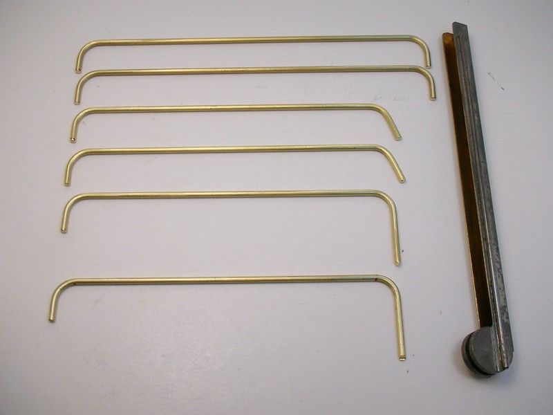
Fred's memories were of brass rod, not tube, so that's what I used. Here are the rails:
That gizmo on the right is a custom made tube bender made for me by the best scratch builder in the world.....thanks again Man!. I didn't need to use it on rod but I like the "big radius" look on these old R&C chassis.
Here's my Rick's Jig with the jig wheels, jig motor and bracket. All the jig's neato pin holes allow me to set up the angled main rails that Fred remembered:
The 3-tappered rails are in place along with the drop arm upward stop:
Next the "jumbo" outer rails were added. The chassis was pretty flexi until I added the "jumbos". They really stiffened things up. Instead of just bending the body mounting pin tube up to clear the "jumbo" rails I decided to notch them:
All the soldering is done and the chassis is ready to have the extra crap-O-la cut off and the "buff" put to it:
Next up....shiny brass .
Rick Thigpen
Check out Steve Okeefe's great web site at its new home here at Slotblog:
The Independent Scratchbuilder
There's much more to come...