
Jean-Michel,
nice! Those "P2" did not like their gearboxes and kept breaking them... 
They were OK for short races but were smoked by the lighter USRRC cars...

|

The Dokktor is IN


Posted 10 October 2013 - 06:33 PM
Jean-Michel,
nice! Those "P2" did not like their gearboxes and kept breaking them...
They were OK for short races but were smoked by the lighter USRRC cars...
Philippe de Lespinay
The Independent Scratchbuilder
Posted 14 October 2013 - 12:08 AM
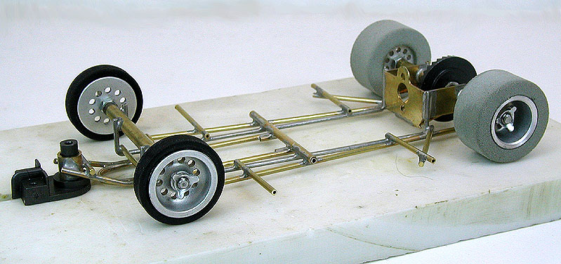
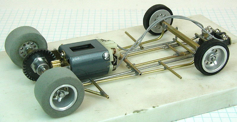
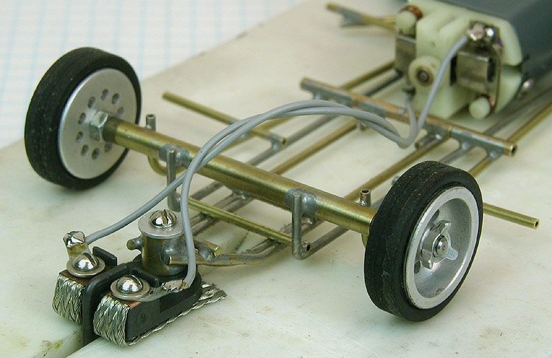
Chassis is now done; here are some photos:
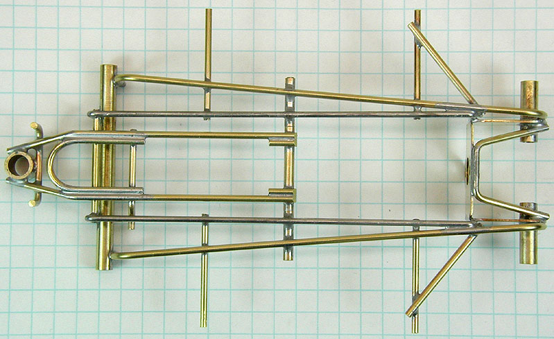
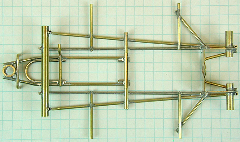
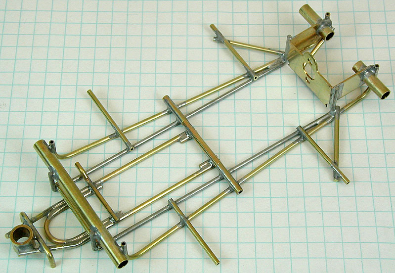
And, some technical details:
The motor bracket is a Russkit #795.
Inner rail is .055" piano wire, the outer rail is 1/16" brass tube.
Bracket brace, pin tube braces and drop arm are built with 1/16" brass rod.
The drop arm hinge pin is .065" hypodermic tubing (the same light-weight stuff the Russkit team is using for the main rails on some of their chassis), and the guide tube is thick (.032") wall brass tube (for a bit of extra weight where it does a great deal of good).
The bare chassis as shown weighs 21 grams.
The bare Team Russkit chassis, built mainly with .065" hypodermic tubing instead of brass tube, rod and piano wire, weighs only 15 grams. You can see a replica of this chassis here.
Team Russkit however may have realized 15 grams was actually too light for a chassis, because there is no mention in the race reports of hypodermic tubing being used after the first race.
Compare the chassis weight to a stock Russkit "23" motor which weighs 31 grams (with pinion and lead wires), and you can easily see why chosing can-drive over endbell drive will significantly shift the center of gravity toward the rear tires.
Next: Prepping the magnesium wheels, tires, axles and hardware.
Steve Okeefe
I build what I likes, and I likes what I build
Posting Leader

Posted 14 October 2013 - 12:20 AM
Wow Steve you have excelled yourself with the chassis! 

 Literally like it's just jumped out of your original chassis drawings!!!
Builder

Posted 14 October 2013 - 07:37 AM
X2 
Paul Wolcott
Posting Leader

Posted 14 October 2013 - 09:00 AM
Grand Champion Poster

Posted 14 October 2013 - 09:17 AM
Seeing the chassis you've built, it's like an archaeologist uncovering dinosaur bones. "This" is the way it was back then. It blows my mind that they raced such light chassis'. I've read the phrase before, but I guess this was "the dawn of time" with respect to "big time" competitive slot racing and they were just feeling their way along. I know other recreations have borne out that scratchbuilding and related philosophy changed rapidly as they progressed through those early days/months/years.
Posting Leader
Posted 14 October 2013 - 09:43 AM
The Independent Scratchbuilder
Posted 14 October 2013 - 10:27 AM
Paul and Pablo,
Thanks!
Don,
Thank you! I did spend some extra time on the design of the drop arm, wanting to concentrate what little weight there is toward the front where it will not only help keep the guide in the slot, but improve the electrical contact as well.
The extra bits of brass rod at the point where the drop arm attaches to its hinge tube are simply to enlarge (and thereby strengthen) the solder joint. It's amazing to think that builders back then used only two tiny solder joints to keep the drop arm attached to the chassis!
Richard,
Right you are! The term that comes to my mind is "flimsy contraption"; like some of the very earliest airplanes made of wood and fabric, that were little more than powered kites.
But there is some method in the madness. The whole idea behind the super-light weight construction was to improve the "power-to-weight" ratio. You may note that through 1966, as the motors became more powerful, the builders incrementally added more and more weight to the chassis to improve handling.
Steve Okeefe
I build what I likes, and I likes what I build
Mid-Pack Racer

Posted 16 October 2013 - 03:29 PM
Builder
Posted 16 October 2013 - 04:00 PM
Let me know if you need anything, Ken
Paul Wolcott
The Independent Scratchbuilder
Posted 19 October 2013 - 11:31 PM
Time to do the donuts! That would be tire donuts.
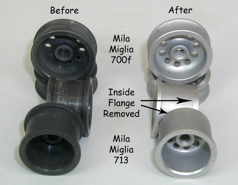
First I prep the wheels. Aside from cleaning, I've cut the rear wheel inner flange off to make it easier to seat the tires:
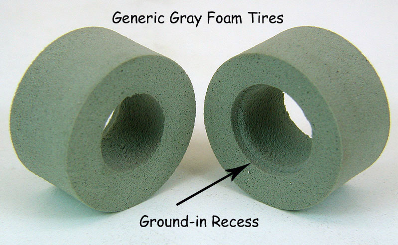
Next, I prep the donuts by cutting a recess into one side only. This recess will fit over the flange on the outsides of the rear wheels:
Next they get glued up (along with the front tires) and set aside to dry. While they are drying, I prep the axles and hex jam nuts. The hex jam nuts need some extra attention:

I picked generic .093" thick hex nuts over some .063" thick K&B #910 jam nuts I have. Why? Because I want to have at least three threads engaged in the threaded axle.
Here's the math: at 40 threads per inch (TPI), the pitch is .025" (the threads are 25 thousandths apart). So, if the hex nut is .093" thick, it will have about 3-3/4 threads. If the hex nut is .063" thick, it will only have 2-1/2 (bigger risk of stripping out).
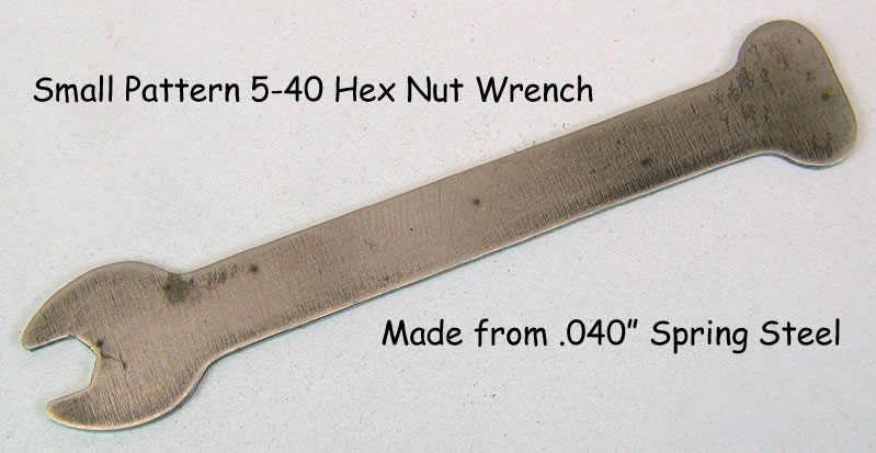
After the glued-up tires dry (overnight) and are cut to size, I am ready to begin basic assembly. I did not have a thin wrench for these small pattern hex nuts, so I had to make one:
I use various spacers to get the wheel track where I want it, and I'm ready to prep the knock-off nuts.
Why jam nuts AND knock-off nuts? The jam nuts are made of steel and are strong, so I use them to lock the wheels onto the axle solidly. The kock-off nuts are made of aluminum and not very strong, but are "wheel bling", so I use them.
Here's the prep on the knock-off nuts; the nuts to be used on the front wheels are reduced in thickness:
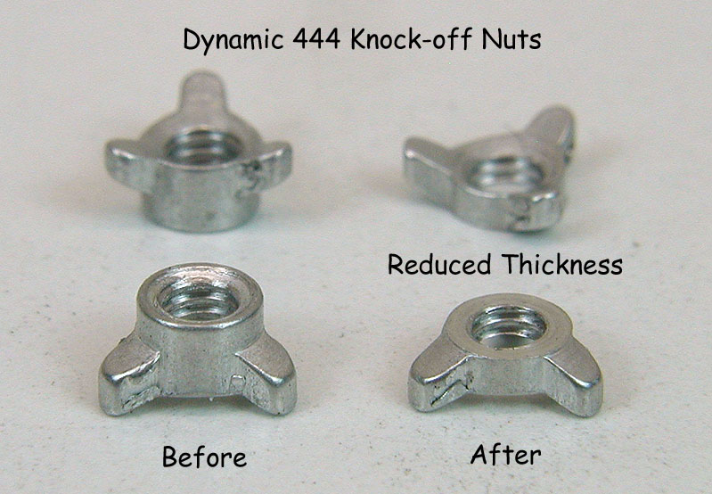
Again, why? Simple, so they fit inside the narrower front wheels:

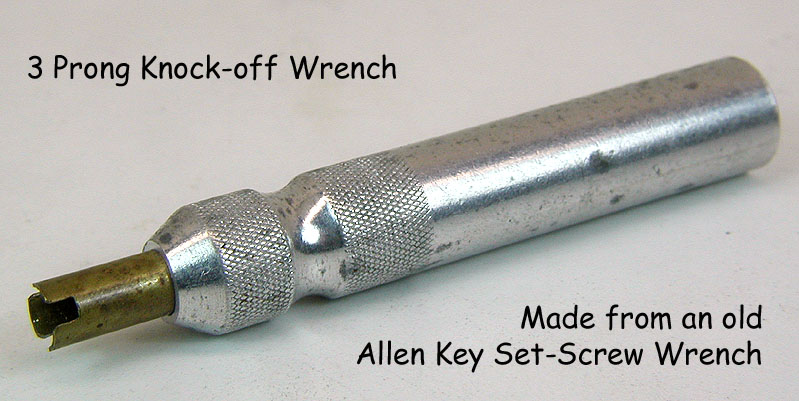
Tightening down the knock-offs (especially 3 prong) without mangling them requires a special wrench. I could have used the manufacturer's wrench:
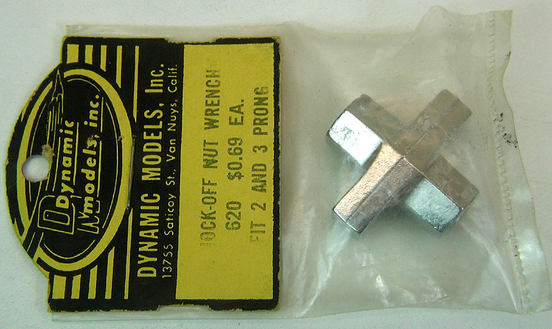
But chose instead to make my own:
Here's the chassis with the wheels and hardware (and bling) all installed:
Next up: Motor mayhem...
Steve Okeefe
I build what I likes, and I likes what I build
Builder
Posted 20 October 2013 - 12:45 AM
Paul Wolcott
Posting Leader
Posted 20 October 2013 - 07:25 AM
Age scrubs away speed!

Posted 20 October 2013 - 07:42 AM
Thanks for the trick of making a nest for the flange on the donuts <G>
I'd like to know if Steve made a special "gizmo" for cutting that groove into a doughnut. He's like that, you know. <LOL>

The Independent Scratchbuilder
Posted 20 October 2013 - 10:06 AM
Why Bill, how did you guess?
Yes, I made a "gizmo" to cut the recess in the donuts... after all, Gizmos - R - Us!
You want I should show the gizmo? It starts off with a 2x4 and a spade bit... 
Steve Okeefe
I build what I likes, and I likes what I build
Body Painter Extraordinaire

Posted 20 October 2013 - 10:19 AM
That's looking great!
Steve, did you coat those wheels with something to stop corrosion or going to allow them to grey with age?
Jairus H Watson - Artist
Need something painted, soldered, carved, or killed? - jairuswtsn@aol.com
www.slotcarsmag.com
www.jairuswatson.net
http://www.ratholecustoms.com
Check out some of the cool stuff on my Fotki!
Grand Champion Poster

Posted 20 October 2013 - 11:31 AM
Hi Steve,
Everything is looking great
I know you've always liked Milia Miglia wheels and I always wondered "why"? Now I know, with a few tweaks they look GREAT!
I'm inspired. I've got an idea for some "fancy lad" wheels for my GP car.
Thanks and build on!
Rick
Rick Thigpen
Check out Steve Okeefe's great web site at its new home here at Slotblog:
The Independent Scratchbuilder
There's much more to come...
The Independent Scratchbuilder
Posted 20 October 2013 - 12:29 PM
Paul E. & Jairus,
Cleaning and protecting magnesium wheels has been the subject of some discussion, it seems as though there are lots of different ways, with most proponents claiming their way is best.
Let's start by saying I am not an expert on the subject of chemistry, metallurgy or machining, but like most everyone else here I know their are at least two ways to manufacture slot car wheels; casting and machining. Cox magnesium wheels are cast, and Mila Miglia magnesium wheels are machined from stock.
This seems to make a difference in the way they react to their environment. While cast magnesium wheels (such as Cox) seem to corrode quickly and severely, machined magnesium wheels (such as Mila Miglia) are much slower to react.
The Mila Miglia wheels you see in the (before) photo in this thread are something like 48 years old and have never been used. Their surface is darkened considerably, but there is no evidence of the "fuzzy" corrosion so common on Cox cast magnesium wheels. This is not to say Cox wheels are "bad", only that they are different.
Anyway, to answer your questions, I threw the wheels in my tumbler with some water and laundry detergent intended for front loading washing machines (low sudsing) and ran it for 3 hours. I limited the tumbling to three hours so that I didn't "round-off" the edges of the wheel flanges too much.
When it was done the contents of the tumbler looked like a gray ice cream sundae! I did this tumbling to roughen the surface corrosion in preparation for the next step, which will take considerably longer if you don't tumble the wheels first. Ask me how I know.
Next step is to chemically reduce the corrosion. I placed the wheels in small (about 2 cups) plastic container and added about 1 cup (enough to cover them completey) of a mild acidic liquid (a 50:50 mixture of water and something called "CLR"). CLR is a Calcium / Lime / Rust (thus the name "CLR") remover commonly available at most local supermarkets, usually near the "Comet" cleanser and RIT dye.
There is nothing particulary magical about CLR. What is important is that is mildy acidic, somewhere between lemon juice and soldering acid.
Upon adding the CLR/water mixture to the wheels in the cup, it will foam up and appear to be eating the wheels alive, but not to worry, that is not actually happening!
Stir about once per minute to refresh the reaction (I use my finger - it's not that acidic folks!) After about three or four minutes, you may note that the liquid is getting warm from the chemical reaction. Add fresh water to stop the reaction and inspect the wheels. If they are not as bright as you want, repeat the process. Each batch is different; this batch of wheels took three baths in the liquid.
When you're happy with the wheels, just rinse them throughly (two or three minutes under clean running water) and dry them with a towel. That's it! You don't need to add or do anything else. How do I know this? As an experiment, I cleaned a half-dozen Mila Miglia wheels this way about three years ago, and did nothing else to them except put them back in their original packaging. They are still clean and bright today; no corrosion or even surface darkening.
Any questions, just ask!
Steve Okeefe
I build what I likes, and I likes what I build
Age scrubs away speed!
Posted 20 October 2013 - 01:51 PM
You want I should show the gizmo? It starts off with a 2x4 and a spade bit...
I might have used dowels & a forstner bit.
The Dokktor is IN
Posted 20 October 2013 - 02:59 PM
When you're happy with the wheels, just rinse them throughly (two or three minutes under clean running water) and dry them with a towel. That's it! You don't need to add or do anything else. How do I know this? As an experiment, I cleaned a half-dozen Mila Miglia wheels this way about three years ago, and did nothing else to them except put them back in their original packaging. They are still clean and bright today; no corrosion or even surface darkening.
This process on the Mila Miglia wheels as described works really well. I personally add one ingredient after I am sure that any water has dried up: I spray the wheels with Eagle One spray wax designed for the finish of automotive paint. Once dried, the wax is then polished with a cotton cloth. No issues with corrosion or discoloration ever since.
I also reviewed Cox magnesium chassis and wheels cleaned and protected following my personal method published nearly 15 years ago, and noted than no signs of new corrosion have appeared.
Philippe de Lespinay
The Independent Scratchbuilder
Posted 20 October 2013 - 03:32 PM
Eagle One spray wax - got it.
Thanks!
Steve Okeefe
I build what I likes, and I likes what I build
Builder
Posted 20 October 2013 - 07:37 PM
Paul Wolcott
The Independent Scratchbuilder
Posted 27 November 2013 - 02:11 PM
Time to build... the motor.
This will be a full-boat early 1966 racing motor, with OEM parts made by Mabuchi and Igarashi, and marketed by Revell, Monogram, Strombecker and Tradeship. An eclectic mix to be sure!
The only parts that will remain completely stock are the motor brushes and springs; everything else gets some sort of treatment to make it work better or be more reliable.
It's been a long time since I've built up a racing motor from individual components, so let's see how I do...
I'll start with the can, and I've picked a pitiful example of a Revell - Mabuchi FT-16:
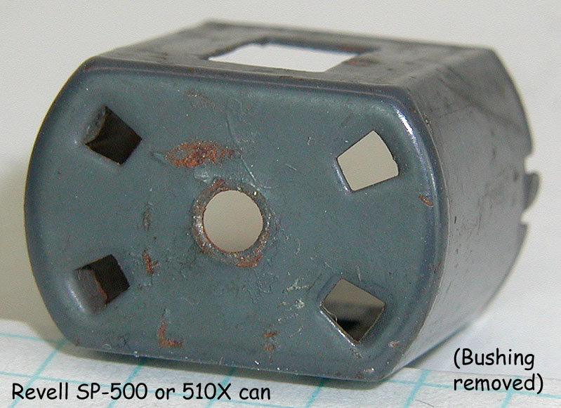
Corroded inside and out:
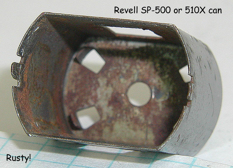
This can gets a bath in Zip-Strip to soften the 50 year old paint, then a stiff wire brushing to remove every trace of paint and corrosion on the outside and as much as I can reach on the inside. Next another bath, this time in Naval Jelly to reduce the corrosion I can't reach with the wire brush.
Then I enlarge and center the bushing hole in preparation for the endbell bushing I will install later.
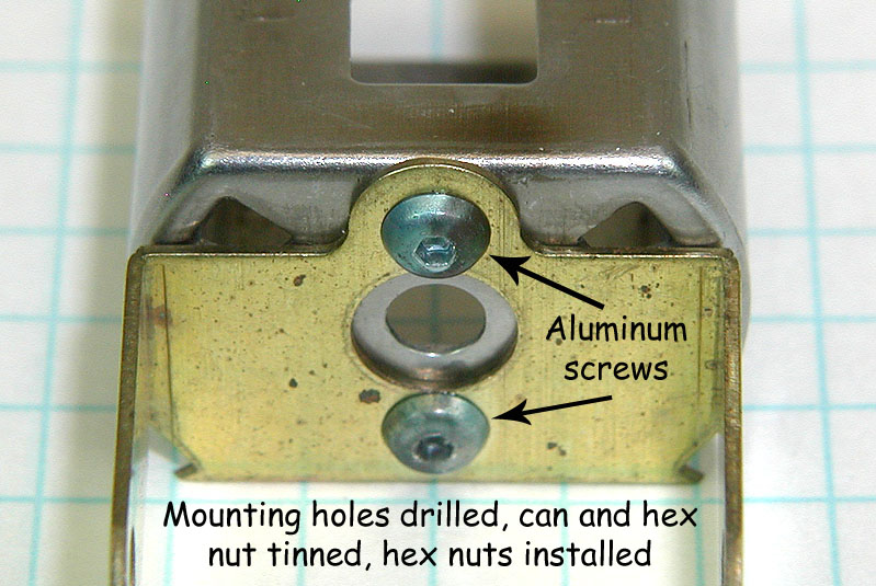
Next I drill the motor mount holes (this will be a can-drive motor) to match the bracket I'm using, and tin the inside of the can (just the bottom, where the can bushing and mounting hex nuts will go).
Now I need to tin the hex nuts. Have you ever tried to tin something as small as a 2-56 nut without getting solder in the threads? Here's one way to do it:

The trick is to use aluminum screws to prevent the solder from getting in, and also to hold the nuts so you can tin them:

Note how the spacer washer is used to make the screw end come up flush with the face of the nut - makes tinning a bit easier.
Once you've got both hex nuts tinned and cleaned up, assemble the can and motor bracket using the aluminum screws and tinned hex nuts:
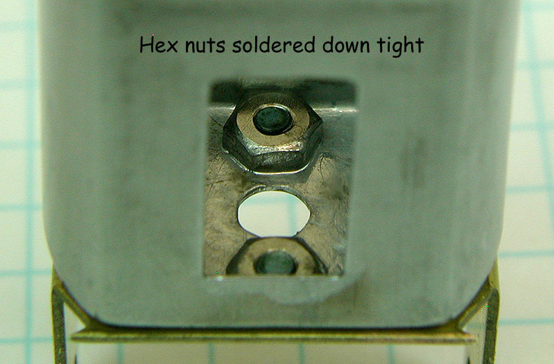
If you're nervous about soldering the motor bracket to the can, wipe the face of the bracket with a little motor oil. Place a dab of paste flux around each hex nut and hit it with a hot iron. The result should look something like this:
Clean everything up and stick the endbell on temporarily. Mark and drill holes for 2-56 endbell to can mounting screws. I located them on the sides rather than the top and bottom because this is a can drive motor; the endbell end is forward and close to flush with the bottom of the chassis. I could have used 0-80 screws, but this is supposed to be a primitive early 1966 motor build. Now I'm ready for paint:

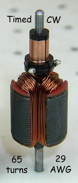
While the paint is drying, I'm on to the armature. No wimpy stock or machine-wound arm for me; this is a race motor. Here's the parts I'm starting with:
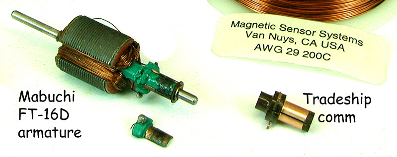
A sorry-looking Mabuchi FT-16D armature from a Monogram X-110, a replacement Tradeship clockwise timed commutator and some 29 gauge magnet wire. That should do it.
Check the reported winds for the first race (this is just supposed to be an example of what builders were doing in early 1966):
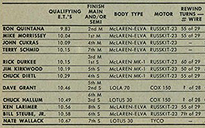
A lot of 29 gauge arms here! The number of turns range from 50 to 60 per pole, except the Steube entry says "7 ft of 29". Seven feet of 29 works out to about 60 turns, except if they're wound tight and neat, then it would be more than 60 turns. This is a Steube wind, what do you think? I think I'll wind 65 turns and enjoy the insurance.
I'll refrain from explaining how I wound this armature because an accurate expanation has already been posted. Regardless of the arm size (16D or 36D), this is pretty much how I did it.
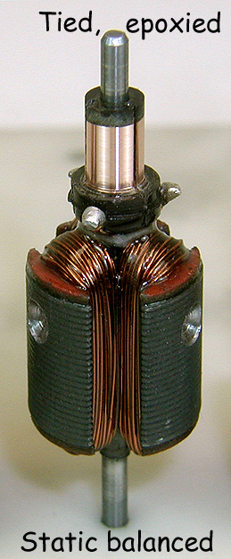
At any rate, here's the finished product:
Here are the major components ready to assemble into a motor:
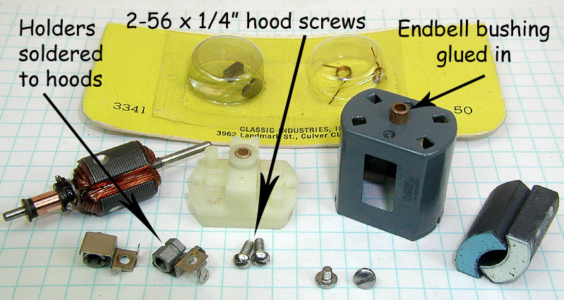
I've noted the can bushing has been glued in (with J-B Weld), the brush holders have been soldered to the brush hoods, and the hoods will be attached to the endbell with 2-56 x 1/4" machine screws.
Soldering the holders to the hoods is very important when building a race motor using a white Mabuchi endbell. Rick Thigpen has explained how and why he does it, and I have added an explanation of my own how and why here.
The reasoning behind why I've chosen long machine screws to mount the brush hoods should be clearer once you've read the explanations.
You might also notice I've glued a bakelite oil slinger to the end of the commutator (with J-B Weld).
Once all the parts are tweaked, assembly goes quick enough, and the finished motor is mounted in the chassis:
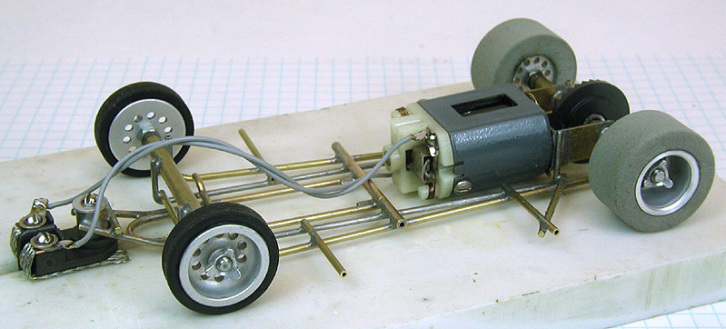
Next up, the body.
Steve Okeefe
I build what I likes, and I likes what I build
Posting Leader
Posted 27 November 2013 - 03:56 PM
the finished roller looks superb
Builder
Posted 27 November 2013 - 04:50 PM
I'm loving it Steve.
Paul Wolcott


