

Okay, it'll be coming your way tomorrow, after the monsoon ends.

NASCAR 'Cheerios' Johnny Benson 4.5" hardbody
Started by
Pablo
, Jun 12 2021 12:00 PM
127 replies to this topic
#51

Bill from NH
-

- Full Member
-

- 14,854 posts Joined: 02-August 07
Age scrubs away speed!
- Gender:Male
- Location:New Boston, NH
Posted 09 July 2021 - 08:27 AM
Bill Fernald
I intend to live forever! So far, so good.
I intend to live forever! So far, so good.
#52
Pablo
-
- Administrator
-
- 18,466 posts Joined: 20-February 06
Builder
- Gender:Male
- Location:Cleveland, Tennessee
Posted 09 July 2021 - 08:56 AM

- Bill from NH likes this
Paul Wolcott
#53
Sloter
-

- Full Member
-
- 159 posts Joined: 27-May 21
Mid-Pack Racer
- Gender:Male
- Location:Venice, FL
Posted 09 July 2021 - 09:11 AM
In the end, a combination of Super Glue, wing and filament tape, all worked well (never did get around to trying the Shoe Goo). Was it all worth it? With all that stuff up high, how much weight did I save? If I had weighed the kit before butchering I could answer to that

Keith Tanaka verified the 2 front side windows don't need to be installed. Just the windshield, rear window, and rear side windows.
I won't apologize for the end result, I don't think they will fail and they look better than I expected. Would I do it again? Probably not. I'd probably just slap the kit windows in there and add some more lead down low to the chassis to compensate

Yes it is worth it, it gets the weight out of a top heavy car. You will have saved 4/5 grams and that is huge in the handling of the car. I do that to all of my Hardbody Racers! Nice work!
Bob
- John Luongo likes this
Bob Roberts
#54
Pablo
-
- Administrator
-
- 18,466 posts Joined: 20-February 06
Builder
- Gender:Male
- Location:Cleveland, Tennessee
Posted 10 July 2021 - 01:11 PM
Thanks Bob, I'm happy to hear that!
Chassis will be sidewinder with 10/50 gears. Center of left/right balance on the jig motor marked - not an exact science, but it's better than guessing IMO. Center of tube (with spur installed) marked for alignment. Also helps me see where to carve meat out of the tube to let the motor snuggle in close as possible
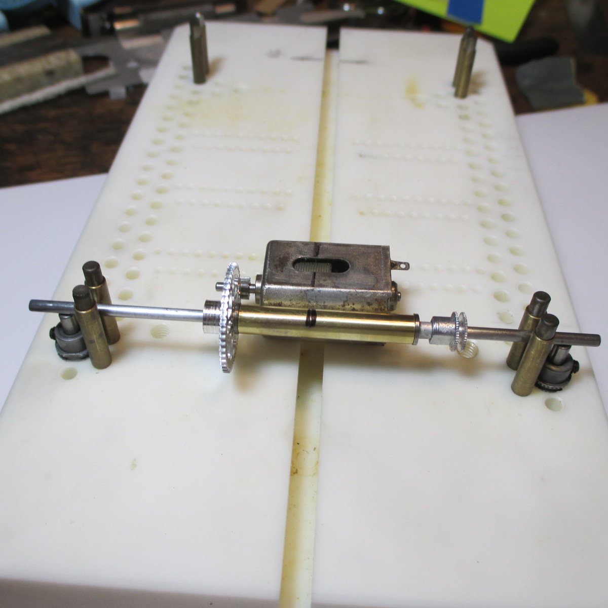
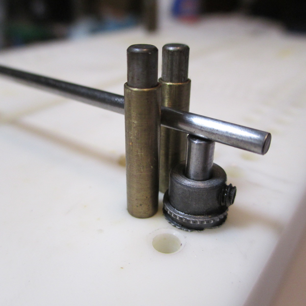
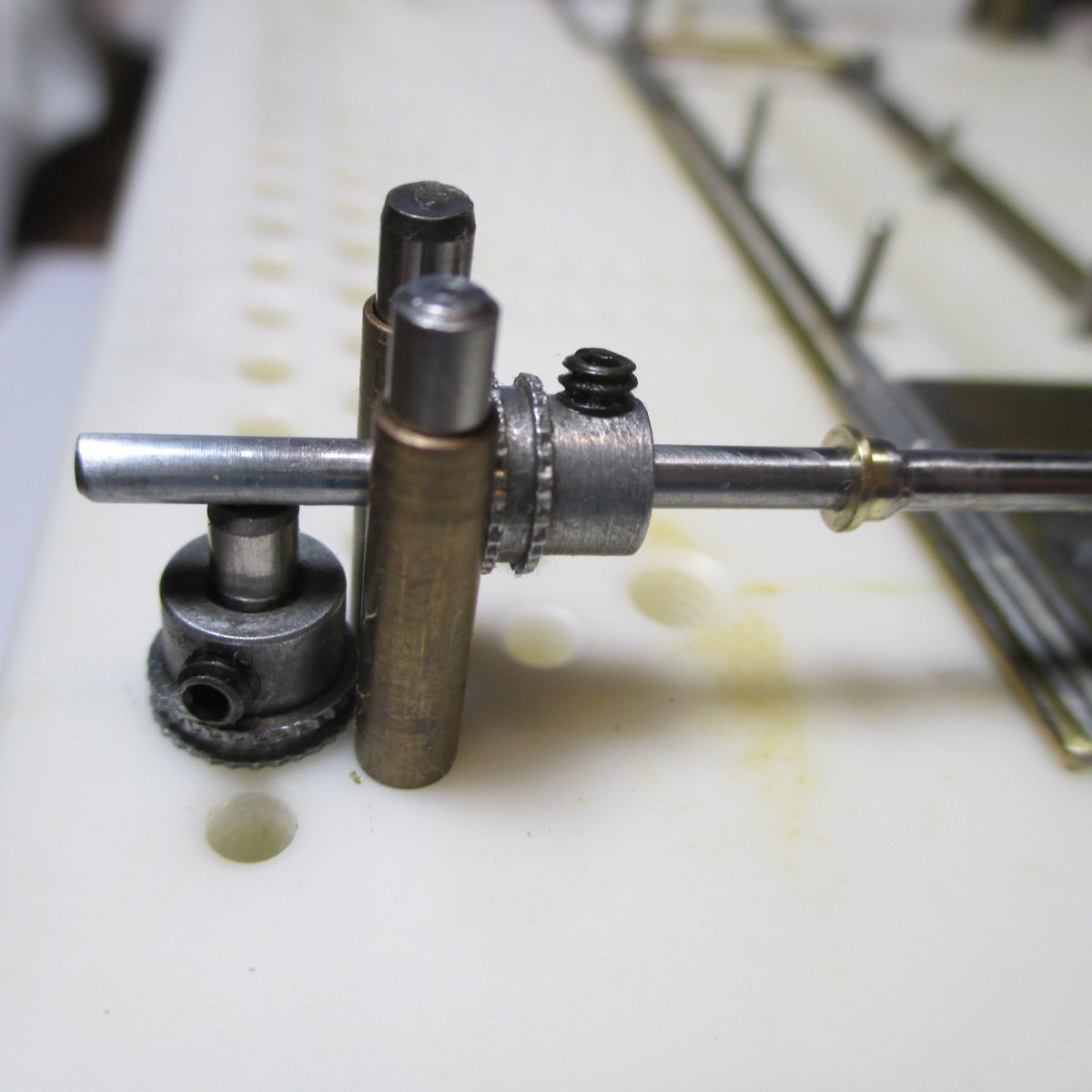
I don't have a jig wheel or block for .050 clearance on a 1+" OD wheel, so I improvised. Made a pair of short jig pins with 1/8 axle hubs to fine-tune the heights. My math says the bottoms of the axles need to be elevated .418" above ground zero to give .050 clearance with 1.03" OD wheels
- Slot Car Rod, Peter Horvath, John Luongo and 1 other like this
Paul Wolcott
#55
John Luongo
-

- Full Member
-
- 694 posts Joined: 01-August 16
Race Leader
- Gender:Male
- Location:Haverhill, MA
Posted 10 July 2021 - 02:39 PM
some years ago we raced hard bodies with factory 4.5" steel chassis in rochester nh. hill climb track. min weight was 158gr. most everyone had great difficulty making them that light. except for one intrepid racer. he made the min weight AFTER he added weight to the car. the genius in that was his car was so light he added the extra weight where he needed it and still made spec. that plastic nascar body he ran was as thin as a lexan one. best regards
- Bud Greene likes this
#56
Bill from NH
-
- Full Member
-
- 14,854 posts Joined: 02-August 07
Age scrubs away speed!
- Gender:Male
- Location:New Boston, NH
Posted 10 July 2021 - 04:57 PM
"In transit."
- John Luongo likes this
Bill Fernald
I intend to live forever! So far, so good.
I intend to live forever! So far, so good.
#57
Pablo
-
- Administrator
-
- 18,466 posts Joined: 20-February 06
Builder
- Gender:Male
- Location:Cleveland, Tennessee
Posted 11 July 2021 - 10:44 PM
Thanks Bill 
Lots of stuff going on in this photo:
-Rear axle tube trimmed for length and motor clearance
-Dummy BB's are same exact size as the final BB's
-Jig alignment, jig motor, and tube all set
-Jig motor tacked to tube with gears in perfect mesh
-One 20 thou alum spacer between spur and BB
-My oiler needle mikes at .043 so I used a piece of .050 tube to space the jig pinion
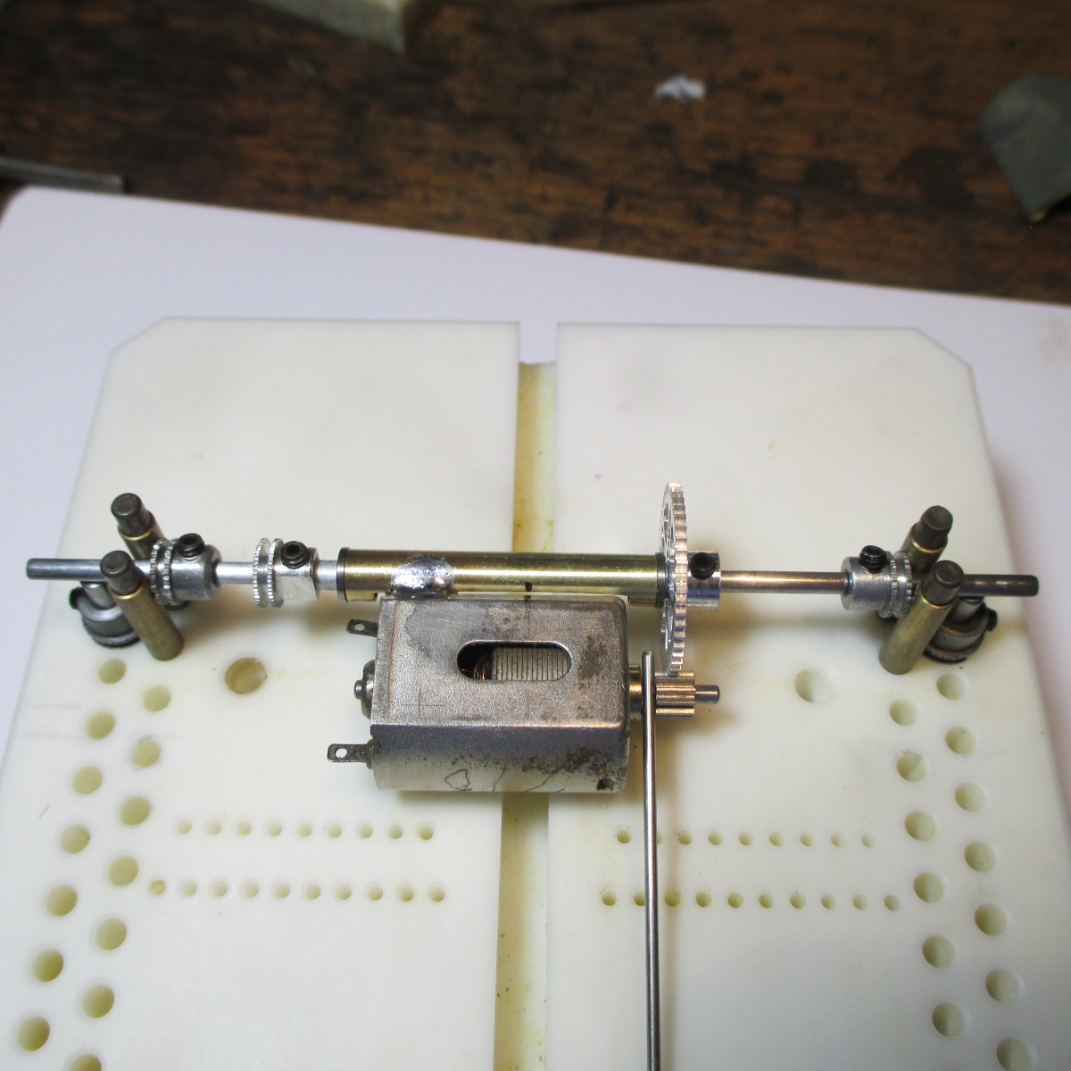
Gears removed and set aside. Everything scrubbed/bathed in Dawn liquid soap and baking soda

- Peter Horvath likes this
Paul Wolcott
#58
Eddie Fleming
-

- Subscriber
-
- 2,954 posts Joined: 27-April 14
Posting Leader
- Gender:Male
- Location:Fayetteville, GA USA
Posted 12 July 2021 - 06:30 AM
What brand and tooth count spur gear is that you are using?
Eddie Fleming
#59
Pablo
-
- Administrator
-
- 18,466 posts Joined: 20-February 06
Builder
- Gender:Male
- Location:Cleveland, Tennessee
Posted 12 July 2021 - 07:19 AM
Sonic 50
- Eddie Fleming likes this
Paul Wolcott
#60
Pablo
-
- Administrator
-
- 18,466 posts Joined: 20-February 06
Builder
- Gender:Male
- Location:Cleveland, Tennessee
Posted 13 July 2021 - 01:35 PM
Jig planning - left inner rail goes straight from the motor edge forward. 1/32 jig pins with 3/32 tube extenders are a perfect match. I didn't plan it - just got lucky. Inner rail set will be 25/32 (.78) wide
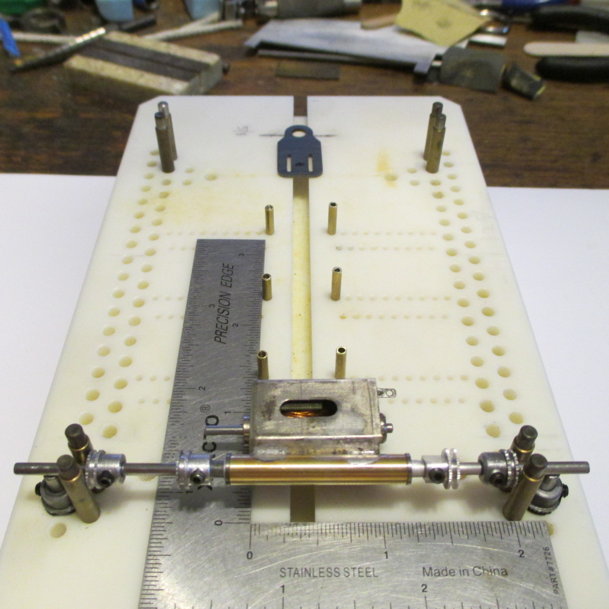
Right side inner rail is the tricky one, and I could go several ways about it. I've thought about ways I could get freaky, including using the (disposable) motor as a stressed member. Also considered a more standard design, snaking the rail around the motor then going forward. We shall see.
Each idea has advantages and disadvantages. Too many bends in wires and rods is never good. Simplicity is always good. It's going to be a top-heavy car, so the chassis needs to be hefty. Lots of things to consider
The Chicagoland Raceway 2 degree tilted steel tongue will be the chassis figurehead for sure 
- Peter Horvath likes this
Paul Wolcott
#61
Pablo
-
- Administrator
-
- 18,466 posts Joined: 20-February 06
Builder
- Gender:Male
- Location:Cleveland, Tennessee
Posted 13 July 2021 - 10:15 PM
I've decided to go "freaky" with the right side rail set - it will attach directly to the motor. The disposable can is stout enough to transfer the power, and I'll design the rails so the connection can easily be broken and re-attached if the motor needs to come out
- Peter Horvath likes this
Paul Wolcott
#62
Pablo
-
- Administrator
-
- 18,466 posts Joined: 20-February 06
Builder
- Gender:Male
- Location:Cleveland, Tennessee
Posted 14 July 2021 - 11:31 AM
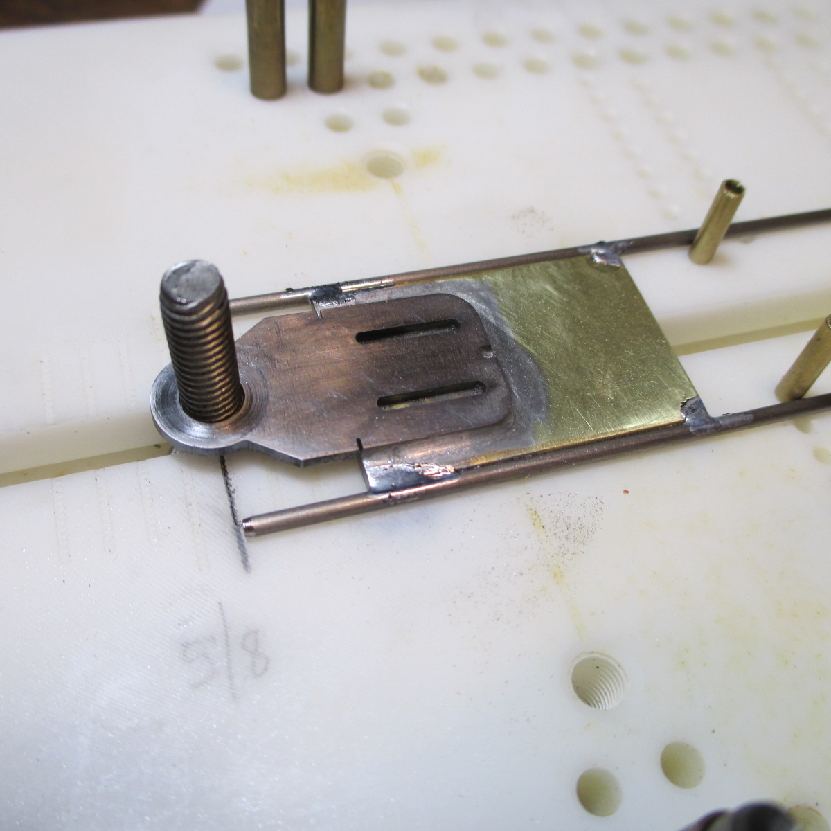
C/R tilted tongue attached to 1/16" thick, .78" wide, 1 1/8" + long brass chunk with Koford silver solder. Everything about the design of this tongue makes alignment easy and guarantees perfect flag angle for a 15/50 thou clearance slope

Rotating surfaces faced with Magnehone, of course
- Slot Car Rod, Peter Horvath and Bud Greene like this
Paul Wolcott
#63
Pablo
-
- Administrator
-
- 18,466 posts Joined: 20-February 06
Builder
- Gender:Male
- Location:Cleveland, Tennessee
Posted 14 July 2021 - 12:05 PM
Now I can plan the rails - haven't decided on brass or wire or how many, yet. But I am committed to the "right side soldered straight to the motor can" plan
- Peter Horvath likes this
Paul Wolcott
#64
Pablo
-
- Administrator
-
- 18,466 posts Joined: 20-February 06
Builder
- Gender:Male
- Location:Cleveland, Tennessee
Posted 14 July 2021 - 09:41 PM
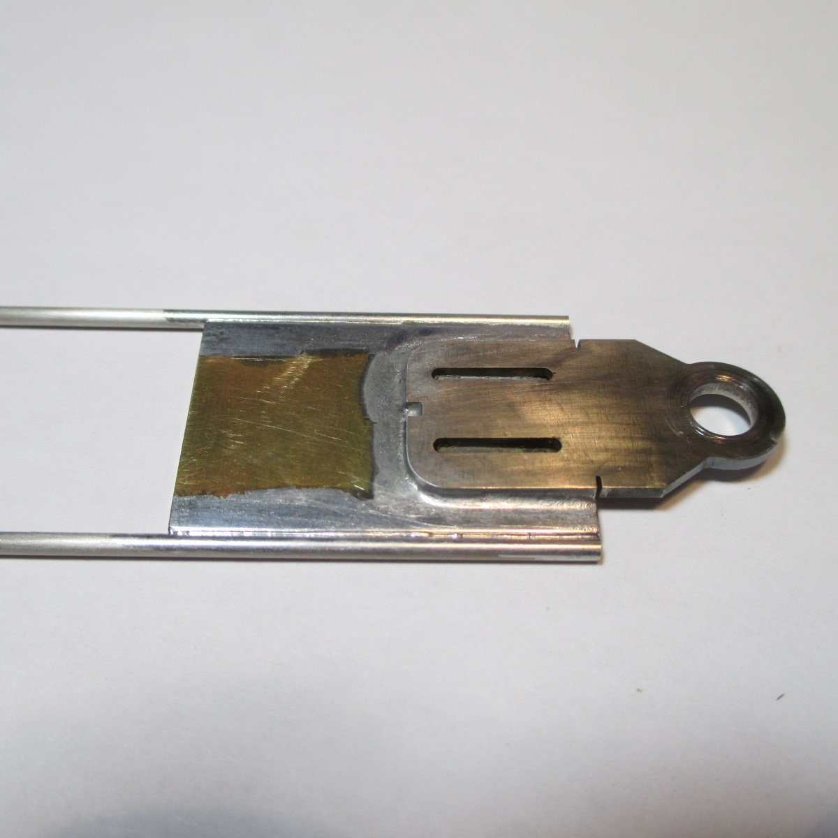
Right side inner rail tacked straight to the (jig) can. The architecture will get stronger as I progress.
.063 C/R plated wire tacked to the chunk
- Peter Horvath likes this
Paul Wolcott
#65
Pablo
-
- Administrator
-
- 18,466 posts Joined: 20-February 06
Builder
- Gender:Male
- Location:Cleveland, Tennessee
Posted 15 July 2021 - 08:23 PM
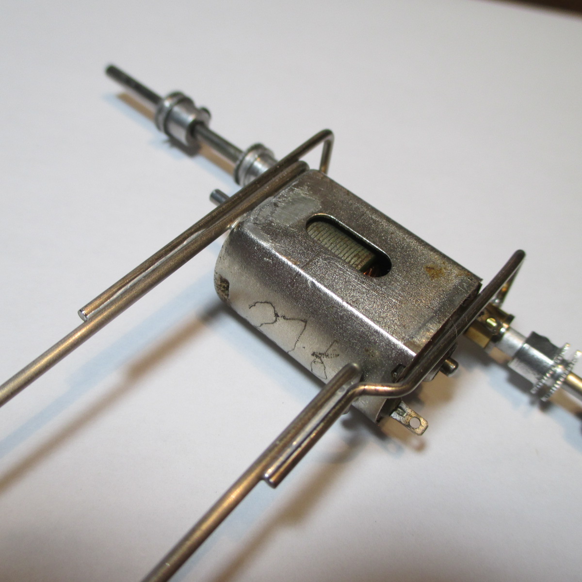
Chunk, tongue, and inner main rail done
Jig motor will be removed soon after this photo before it gets too "attached" to the works LOL Outer supports are .055. I like a strong motor box, but at some point the main rails need to flex and let the tires grip
- Peter Horvath and Bud Greene like this
Paul Wolcott
#66
Pablo
-
- Administrator
-
- 18,466 posts Joined: 20-February 06
Builder
- Gender:Male
- Location:Cleveland, Tennessee
Posted 17 July 2021 - 08:49 PM
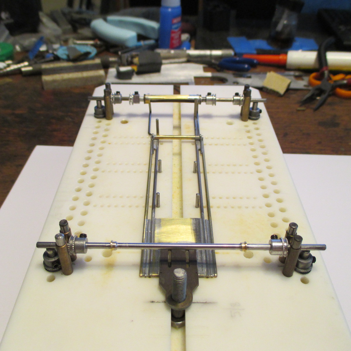
This car's purpose is to race competitively. Top heavy body needs a heavy chassis with lots of de-coupling and a decent amount of flex. Not easy to do. A big priority is to make the huge (>7/8") front wheels help the handling, not hinder it.
I spent a lot of time pondering front axle/wheel management for the Pro-Tracks. It came down to a choice between hard mounting on the main rails/front chunk with "L" uprights, or Iso rails governing a 3/32 wire front axle. I chose Iso.
Twin .063 rails - inner is wire, outer is brass. 3/32 Iso tube braced with .032 wire pieces. I like strong rear ends and I like the hips to have some flex

Whoops, wrong photo, sorry

- Peter Horvath and John Luongo like this
Paul Wolcott
#67
John Luongo
-
- Full Member
-
- 694 posts Joined: 01-August 16
Race Leader
- Gender:Male
- Location:Haverhill, MA
Posted 18 July 2021 - 12:54 AM
not the wrong photo at all. i can clearly see the advantages of flexible hips and a firm rear end. i bet she handles great on a blue king.
- Pablo likes this
#68
Pablo
-
- Administrator
-
- 18,466 posts Joined: 20-February 06
Builder
- Gender:Male
- Location:Cleveland, Tennessee
Posted 18 July 2021 - 08:09 PM
Thanks John Tony P. teaches us, a chassis needs to have flex to provide grip 
.055 Iso hinge wire bits; twin .063 wire rails each side will be uprights for a tinned 3/32 front axle.
Pro-Track fronts trimmed and trued down to .890 OD with edges slightly rounded. They will rotate independently
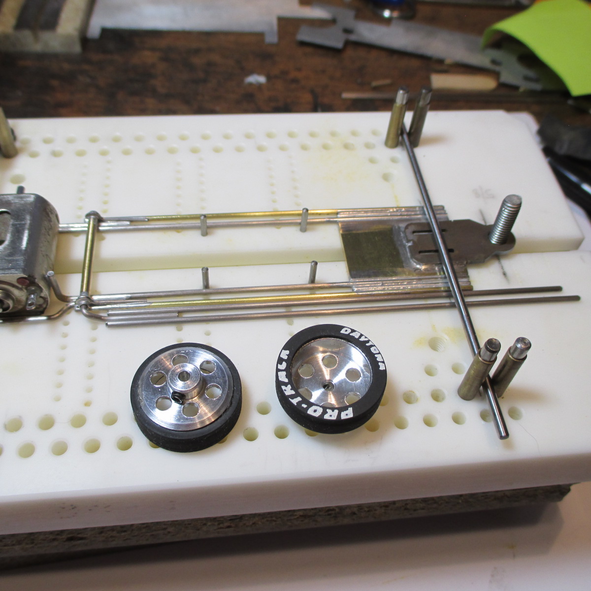
Now I need to heat up the Hakko, get that jig motor out of there, and tin the front axle 
- Peter Horvath, olescratch and John Luongo like this
Paul Wolcott
#69
Pablo
-
- Administrator
-
- 18,466 posts Joined: 20-February 06
Builder
- Gender:Male
- Location:Cleveland, Tennessee
Posted 20 July 2021 - 02:25 AM
My new method of jig axle height setup worked well on the rear, so I did the same on the front.
Elevating the bottom of the axle .378" gives about .020 clearance to a .890 wheel
- Peter Horvath, Eddie Fleming, John Luongo and 1 other like this
Paul Wolcott
#70
Bill from NH
-
- Full Member
-
- 14,854 posts Joined: 02-August 07
Age scrubs away speed!
- Gender:Male
- Location:New Boston, NH
Posted 20 July 2021 - 07:50 AM
A 1/32 scratch builder made wooden jig squares with two vertical screws threw the middle used for adjusting various clearances & wheel diameters. You accomplished the same thing using a different method.
- Pablo likes this
Bill Fernald
I intend to live forever! So far, so good.
I intend to live forever! So far, so good.
#71
John Luongo
-
- Full Member
-
- 694 posts Joined: 01-August 16
Race Leader
- Gender:Male
- Location:Haverhill, MA
Posted 20 July 2021 - 08:54 AM
and pablo, if painted yellow, your design would double as an osha approved axel safety stand. very important when we are working underneath these axels.
- Pablo likes this
#72
Pablo
-
- Administrator
-
- 18,466 posts Joined: 20-February 06
Builder
- Gender:Male
- Location:Cleveland, Tennessee
Posted 20 July 2021 - 01:46 PM
John, funny - OSHA knocked on my door, looked in my apartment, smelled crock pot chicken, looked at my Rat Terrier, said "have a nice day, sir", and left LOL
Seriously, jig motor has been removed and chassis is ready for Iso twin front axle sets
- John Luongo likes this
Paul Wolcott
#73
John Luongo
-
- Full Member
-
- 694 posts Joined: 01-August 16
Race Leader
- Gender:Male
- Location:Haverhill, MA
Posted 20 July 2021 - 03:54 PM
ha ha. pablo, the genius of your "axel stands" is the repeatability of your construction techniques. any tire size, axel height or frame build can be duplicated easily. great idea. AND, your making use of parts that otherwise would have been discarded - repurposing them. i love it!
#74
Bill from NH
-
- Full Member
-
- 14,854 posts Joined: 02-August 07
Age scrubs away speed!
- Gender:Male
- Location:New Boston, NH
Posted 20 July 2021 - 07:20 PM
John, don't forget the RGEO jig.
Bill Fernald
I intend to live forever! So far, so good.
I intend to live forever! So far, so good.
#75
John Luongo
-
- Full Member
-
- 694 posts Joined: 01-August 16
Race Leader
- Gender:Male
- Location:Haverhill, MA
Posted 20 July 2021 - 07:34 PM
thats true, bill. far superior to my line-of-sight string method.


