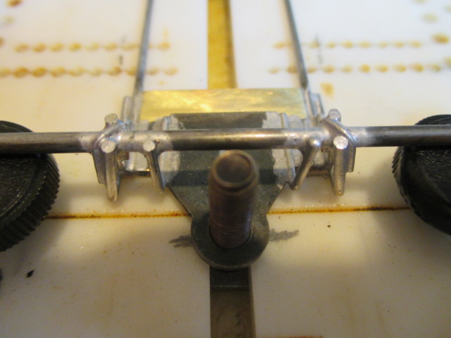
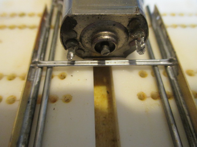
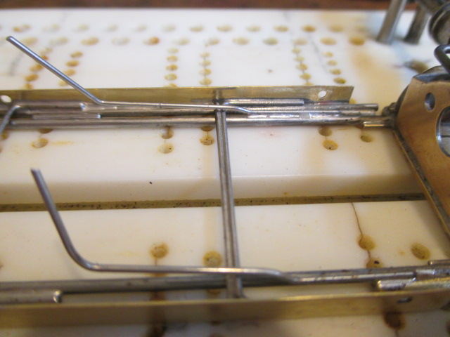
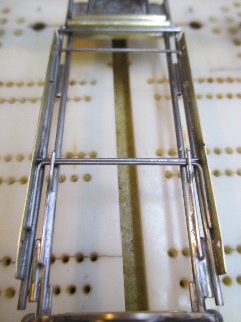
There are a lot of things going on in this photo, Jaaaaaaaaaaaak. 

Everything before this was pretty much standard procedure - build right, build strong, keep the weight low, let the chassis flex but make the motor box rigid, balance the weight, make every part as perfect as possible, don't let the chassis hinder body movement, etc. etc. I think you have learned all that. Now, the plumber rails - this is where the little speed secrets are. It's just plain ol' hard work.
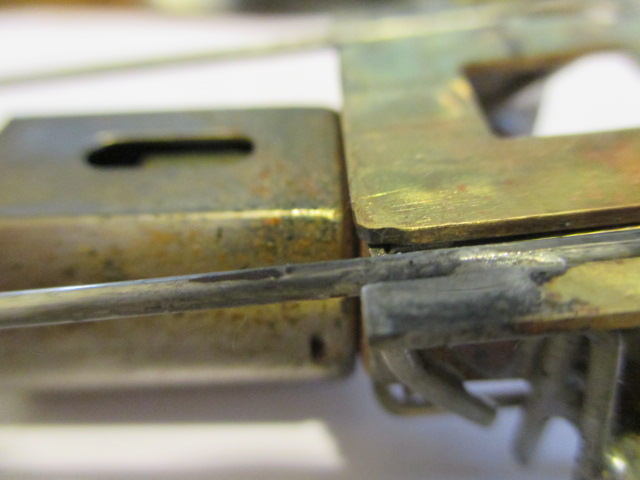
1) I made the wire uprights for the front axle run back down the main rail as far as possible - almost all the way to the rear of the chunk - for a good reason - it's easier to solder wire to wire in at least 1/2" lengths - that way you can let the solder flow halfway, stop, re-flux, solder the other half, etc. You'll get it once you see the Steube video. Having said that, I had to place the plumber hinge (3/32 tubing) near the back of the chunk. This is the way I planned it all along. A piece of 3/32 tube spaces it back the correct distance from the back of the tongue to ensure the .055 plumber wire rails don't get snagged on those uprights. Hope that makes sense  At this point, the 3/32 dummy piece is soldered home to the steel tongue and the chunk - it serves as both a spacer and a brace.
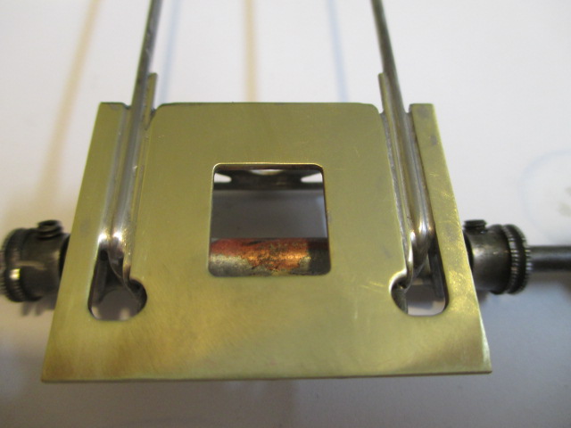
2) The plumber rails are bent and angled down immediately after exiting the hinge - this bend is critical - the rails must lay absolutely flat - this takes some doing to get it right. First, make about 1/4" 90 degree bends in the wire - don't waste time trying to make the angle perfect yet - then make the down angles. The goal is to make those angles so the 90 degree 1/4" bends enter the 3/32 tubes at the bottom of the holes. .055 wires inside .063 holes leaves some room for slop - you want the wires to sit at the bottom of that slop - that way the plumbers can lift, not droop. If you look at the photo closely, you will see mine are perfect. Once you have the little bend perfect, now go back and make the 90 degree angles perfect - then re-check them. You will only get one chance at this, Bunky - make it right first time, or else it just gets more painful. 

3) Not only are the wires at the bottoms of the hinge hole, they need to be centered fore and aft - that way the body mounts can go forward a hair, and back a hair, from your final placement.
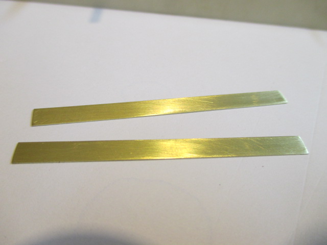
4) The wire studs in the jig are set at 1.400" but I need to remember I'm going to install .015" thick brass strips outside the rails as body mounts. When I finalize the width of the rails I'll set a piece of dummy .015 strip between rail and jig studs.
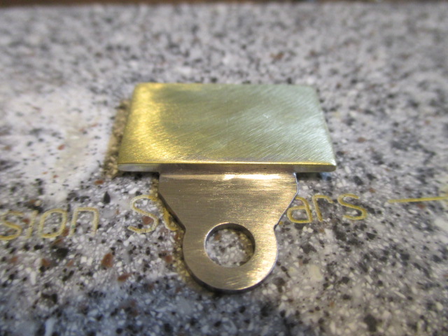
I cut the back ends of the plumber rails slightly ahead of the brackagra ears. The JK Indy 2" body clip holes will be positioned 15/16" and 2 15/16", respectively, behind the center of the front axle. The .015 brass strip body mounts will extend 3/16" past the holes on both ends. Some guys use computer programs to plan all this stuff, Jaak. I just make rough notes, sketches, and calculate rail widths.

![]() :
:


