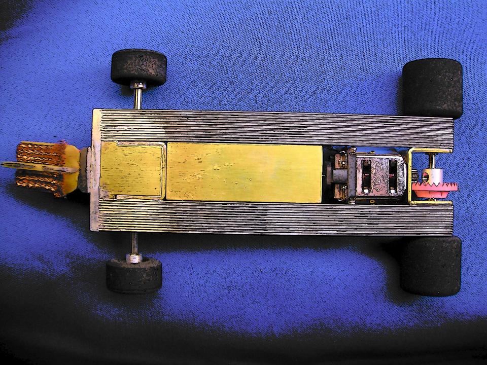
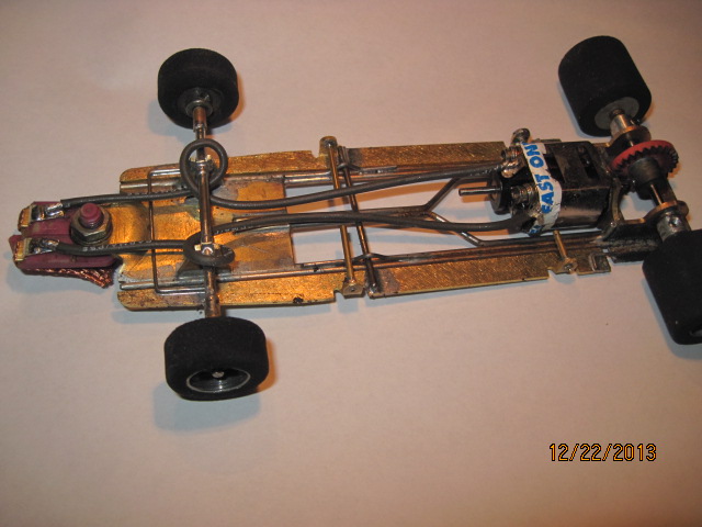
This is my first time posting in this thread. This is the car that won the latest RMRRA race, run on a whim before being tried in a real race first.There are two more images in the RMRRA thread.

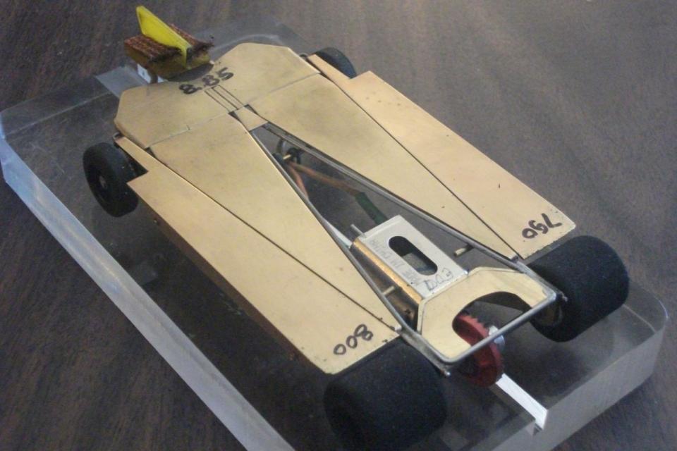
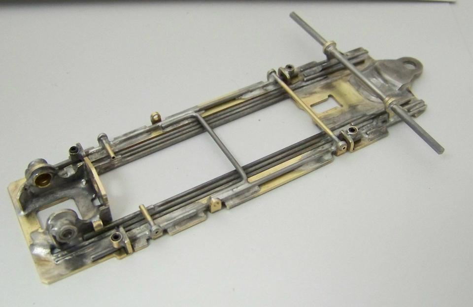
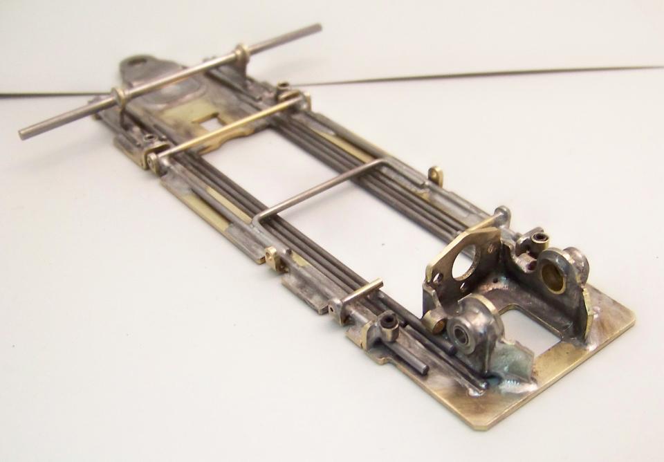
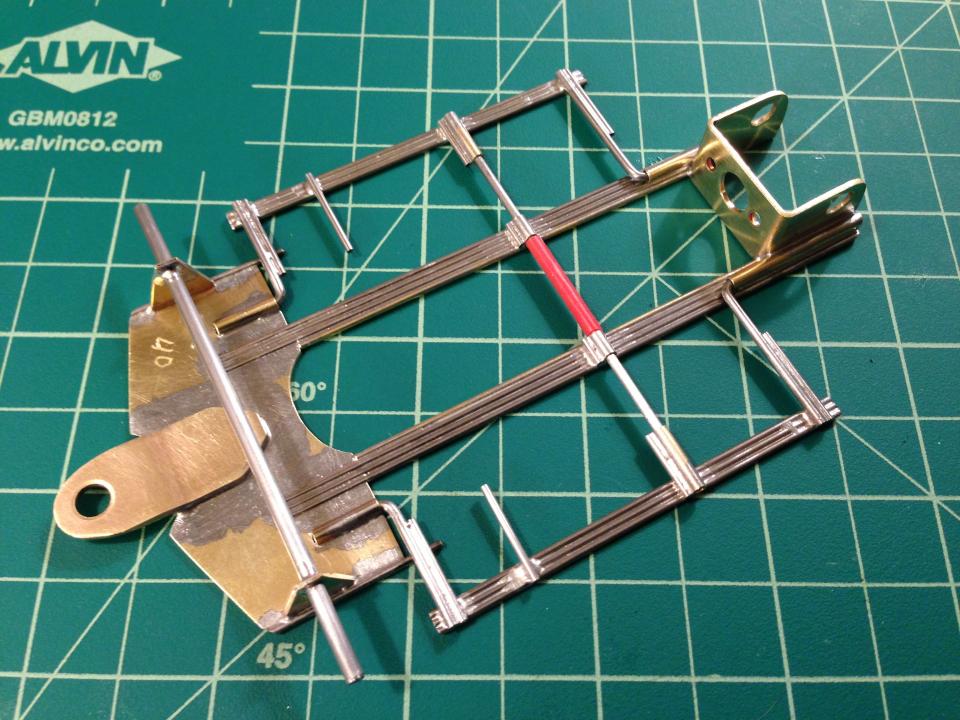
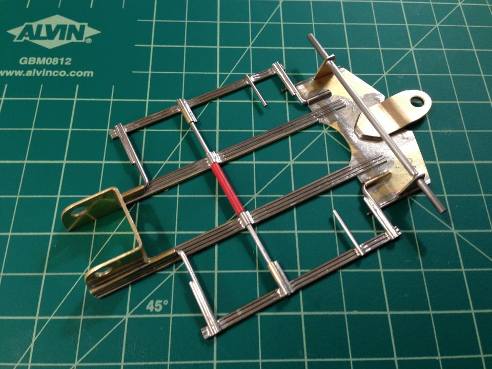
The "main rail" is a single piece of .055 steel starting in the square tube in front, avoiding all of the 90 degree shenanigans of the "tuning fork" (this mechanical engineer can't figure out what that could possibly do) in favor of a "direct" diagonal around the sides of the rear motor bracket, behind the crown gear and back to the front. The main rail is tied together with a small .015 brass gusset near the pivots in front.
The two "mid pans" are, in the F1 cars, the side pans. They are wider here (at the front) and are attached to the front pan (.031 with formed front axle uprights, guide tongue) with a single piece of fore-aft .039 steel wire (for strength and spring) to the outsides and a single piece of fore-aft .047 brass rod (for strong brass-to-brass solder joint and damping) to the inside, alongside the guide tongue. My next version will make the front pan and the side pans all from one piece of .031 brass sheet. So far, I like the modularity of this design, all made from 1" wide strips of K&S .031.
The bat pans are hinged in the back with a piece of .031 wire acting as the down stop. In front, the .031 steel wire snakes through a very tight hole in the front axle upright and through another tight hole in the bent-up tab at the front of the bat pan through a series of 90 degree bends soldered only at the ends inboard of the thru holes. (I am not averse to 90 degree bends, they just have to do something.) These allow a flexing "plumber" motion from in front of the front axle and a flexing bat pan swing supported by the inboard hinge at the rear of the pan, which allows some lateral movement up to the 3.125 maximum width allowed.
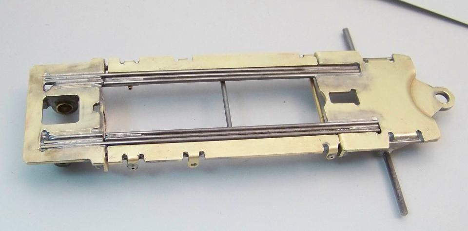
The side pans have a similar bent-up tab with a small hole to pass a piece of .031 wire as the fore-aft locators inside square tube so there is some lateral and up/down freedom but no fore-aft as a cap is soldered on the end. There is a slight pre-load holding the outside of bat pan down.
The .015 side fences have 2mm drilled holes to allow the body pins to float just a little bit. I have been doing this for about 3 years now.
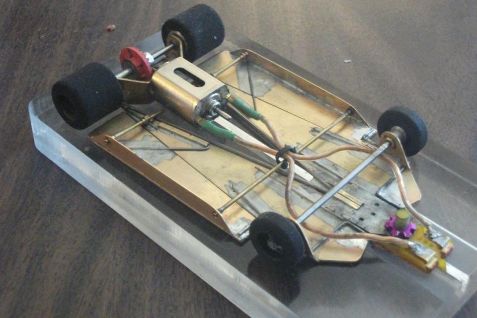
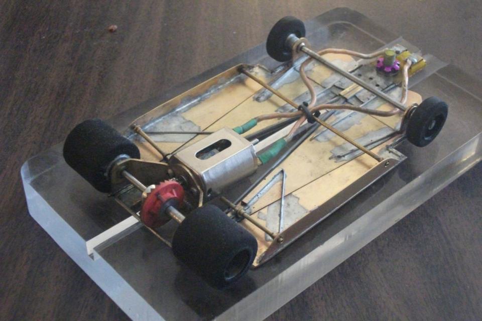
There is a lot of hinge freedom in the aft hinges (alongside the motor bracket). The twist articulation between the front and rear axles is "severe", about 10 degrees or more before any resistance is felt; it will ALWAYS pass the 4 tires in contact tech test! Others likened it to a "rock crawler competition" vehicle suspension. Others have said that it looks like it should really scream on a flat track. I built if for our local King track and it went a full quarter second faster than my previous best Can Am car with no development yet.
I used a Chicagoland steel guide tongue, JK firm fronts in "floating" Slick 7 bushings (the axle rotates, not the tires on the axle, but one tire is not set-screwed down and is free to "differential rotate" on the axle - semi-independent fronts), rear ball bearings, Red Fox guide and a JK Retro Hawk motor.
Nelson Swanberg called me while I was posting and talked me into posting a CAD image of the car, essential to facilitate packaging and getting the fabrication done quickly.

Not revolutionary but evolutionary - an F1 articulation with bat pans added.
Keep it in the slot,
AJ
Sorry about the nerf. "Sorry? Sorry? There's no apologizing in slot car racing!"
Besides, where would I even begin? I should probably start with my wife ...
"I don't often get very many "fast laps" but I very often get many laps quickly." ™
The only thing I know about slot cars is if I had a good time when I leave the building! I can count the times I didn't on one two three hands!
Former Home Track - Slot Car Speedway and Hobbies, Longmont, CO (now at Duffy's Raceway), Noteworthy for the 155' Hillclimb track featuring the THUNDER-DONUT - "Two men enter; one man leaves!"