Hi John,
Excellent with the clamp pics.
I must ask since I been wondering a long time.
Whats is 16D, 26D, 36D?
The difference?
What then is a C-Motor? D-Motor? A????
Measurements?
Regards
Jens

#1176

Posted 09 February 2010 - 12:08 AM
#1177

Posted 09 February 2010 - 01:23 AM
"We offer prompt service... no matter how long it takes!"
"We're not happy unless you're not happy"
"You want it when?"
#1178

Posted 09 February 2010 - 01:30 AM
Please read both of these excellent articles by our buddy the Dokktor. It should answer most if not all your questions
1. http://www.electricd...ess-or-failure/
2. http://www.electricd...mpion-story.htm
Also check this out from the 1967 Auto World catalog:
http://theindependen....... pg 109.jpg
If you don't get the answers you wanted, please ask again.
"We offer prompt service... no matter how long it takes!"
"We're not happy unless you're not happy"
"You want it when?"
#1179

Posted 09 February 2010 - 05:32 AM
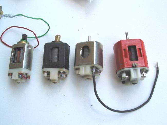
A quick pictoral reference, from left to right: 13D, 16D, 26D, 36D
These were all available in different versions too; all except the 13D first come out with endbell drive, as opposed to the "can" drive shown here (pinion on the can end, instead of the endbell end).
Don
#1180

Posted 09 February 2010 - 06:49 AM
What then is a C-Motor? D-Motor? A????
Hi Jens,
Don's picture pretty much sums up the Mabuchi motors, although there are variations in winds, endbell hardware etc. The various Mura motors are all over the map, as there are subtypes even among the types A,B,C etc. Philippe has shown the various types and posted links to descriptive explanations as well. Also, if you follow Rick T's builds, there's a wealth of information on this... beautifully photographed and documented. There's way more in the Mura, Champion and Mabuchi motors category than I have a clue about, and I think most people really only know the general/basic info.
Interesting reading John. Sometime can you post a photo of your minature "arc welder?"
Yes! Yes please?! I second Bills request of a photo - please?!
Hi Bill and Ernie,
OK, I'll do that when I get home from work, keeping the above disclaimer in mind
-john
#1181

Posted 09 February 2010 - 03:01 PM
Mike Boemker
#1182

Posted 09 February 2010 - 03:37 PM
That was one of the first things I tried when doing this stuff again. It doesn't work nearly as well (with armatures anyway) as razor blades from my experience. I quickly went back to razor blades.
-john
#1183

Posted 09 February 2010 - 04:25 PM
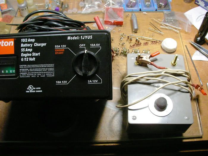
On the left is the car starter/battery charger I got for this from Graingers. I use the 55 amp/12 volt setting. I tried to find something that would do 50-ish amps at low voltage (like 3 or 6 volts), but came up empty. This works fine even though it's less than ideal. On the right is the footswitch I made using a boat starter switch (momentary/normally open). I just ran each side of the switch to a couple of brass terminals on top of the enclosure. One terminal gets hooked up to the starter and the other gets hooked up to a carbon rod from a C cell battery (the old zinc/carbon type) that acts as the "heater". The neg terminal of the starter goes to the com of the arm being brazed.
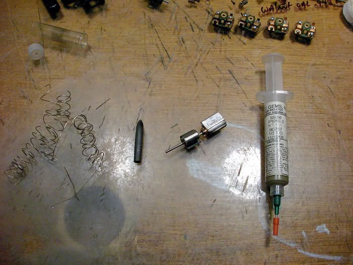
Here are the bits needed to do the brazing. On the left is jeweler's silver (extra easy type...low melting point of around 1150-1200 degrees F I think). I have a draw plate that , by having graduated holes, lets you draw the silver wire down very thin. The silver wire gets work-hardened after a few passes and at that point it needs to be annealed before you draw it down further. Shown is a lifetime supply since you use so little. Not shown is the brazing flux you need to use with this. Just to the right of the coiled silver wire is the sharpened carbon rod I use as my "heater". Just to the right of the carbon rod is an arm with a heatsink/clamp terminal I made you attach the neg from the starter to. I actually don't use this anymore since attaching the neg clamp directly to the com gives a better connection and doesn't seem to hurt it. I always cut the coms after the arms are done so any small marring the clamp leaves on the com plates is removed then. Just to the right of the arm with the heatsink is the jeweler's silver/brazing flux paste syringe I use. This is also "extra easy" alloy that melts at the lower 1150-1200 degree F temp. The syringe should last for a couple of years at least. I squeeze a bit onto the com tab with the stripped magnet wire laying there and then crimpo the tab closed. This gives a good mechanical connection (crimping and brazing) as well as a solid electrical connection (silver). That's all there is to it. I wanted to put a relay in the footswitch box and be able to automatically control how long the connection lasts, but never got around to it. In my usual caveman fashion, I simply count and then take my foot off the switch.
-john
#1184

Posted 09 February 2010 - 05:31 PM
WOW.... How thin do you have to make the silver wire? Is this kinda how most, for sale, arm winders do it?
Or do some depend on the crimp method?
PHIL I.
#1185

Posted 09 February 2010 - 06:02 PM
From what I can tell from taking these things apart, the manufacturers are using some form of resistance spot welding. In other words, there's no additional metal/flux involved and they're using an electric current to fuse the brass com tabs with the copper magnet wire. The setup I'm using will doi thatr if I leave it in contact for a couple of extra seconds, but without a timing relay to precisely control the length of time the circuit is closed I'm as likely to blow right through the com tab and magnet wire as I am to make a good weld. Brazing with silver jeweler's wire allows a bit more leeway as the silver melts at a significantly lower temp than the brass and copper, but still much higher than whatever else might fail in a high-temp situation (usually the magnet wire insulation or something on the endbell).
-john
#1186

Posted 09 February 2010 - 07:49 PM
I intend to live forever! So far, so good.
#1187

Posted 09 February 2010 - 09:22 PM
I haven't tried it on a big wire road course arm but I haven't had any failures with my drag arms. I want to do more testing to see if it will hold up under continuous run situations, but simply do not have time to do that now.
The good news is that the local track may open up under new ownership and in a different location at the end of March or early April. The bad news is that I'll have to drive .7 mile farther. The new location will be 2 miles from the house, not 1.3 miles as the old location was. It's supposed to have a Ogilvie Blue King, Gerding tri-oval and a Hasse drag strip. For the past 2 years I've had to drive about 110 miles one way to the closest track.
"We offer prompt service... no matter how long it takes!"
"We're not happy unless you're not happy"
"You want it when?"
#1188

Posted 09 February 2010 - 09:29 PM
I intend to live forever! So far, so good.
#1189

Posted 09 February 2010 - 10:17 PM
10-4 on the lead. That has been pointed out here (somewhere in this thread) a few times and I've tried it. It seems to take quite a bit of heat to get lead to flow and it's not as easy as solder to get a nice joint. Maybe there's a non-corrosive flux made for pure lead, but I had to stay in contact with the com tabs for a while to get them hot enough to flow lead. Could be my Weller iron too
-john
#1190

Posted 09 February 2010 - 11:29 PM
Thanks for taking the time to post those pix. Which I could see how it's done - video?! LOL!!
Appreciate your time John!!
Ernie
#1191

Posted 10 February 2010 - 08:02 AM
You're welcome of course. I think the video thing isn't going to happen though as I'd have to corral someone into shooting it while I did the deed. It's really not complicated though:
1) Scrape the insulation off the magnet wire where it passes over a com tab. The heat of the brazing is so intense that this step isn't so critical...but you still don't want any carbonized insulation in there. With soldering...even with pure lead, you do have to be sure that the tab and the wire are both clean.
2) Shoot a little of the jeweler's silver paste into the com tab and crimp it closed. I use a small pair of needle nosed pliers and protect the back of the com with a rag folded several times so the pressure doesn't mess up the com.
3) Place the carbon in the positive lead coming off the footswitch and clamp the negative to the com segment you're working on.
4) Turn on the car starter at the 12V/55 amp position & touch the carbon to the front of the crimped tab solidly to be sure of good contact. It's also important that the front of the tab be bright, clean and free of corrosion or old epoxy if it's a recycled com so that it conducts well.
5) Step on the footswitch for 2 seconds to complete the circuit and heat the tab.
The carbon goes from cold to yellow hot instantly and even produces a small flame at the point of contact
After it's all done, I go around each tab with a small brass brush to clean off any residue and be sure the connections are all good. A final check with a multimeter and the arm is ready for tieing and epoxying. These connections are impossible to undo, so it's important to practice practice practice. Wasting a very limited resource like armature parts (commutators) is a real bummer. The good news is that this process adds so much heat so quickly to such a tiny spot, that it seems to be less destructive to coms (especially old ones) than even soldering.
Is this kinda how most, for sale, arm winders do it?
Or do some depend on the crimp method?
Phil, I should add that some of the milder arms from at least some manufacturers seem to be ONLY crimped. I can't comment on how well these hold up from personal experience, but it sure does make taking them apart for reuse easy...so I like those ones
-john
#1192

Posted 10 February 2010 - 10:11 AM
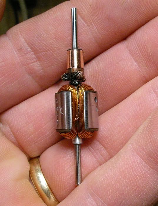
The motor was in fine shape except for the paint being a bit messed up. I stripped it and repainted it, reassembled it with the arm centered in the field and installed the arm with very little endplay. That was about all the motor needed to be up to snuff. It runs really nicely...very smooth and torquey drawing less than 2 amps at full rev after a 3 minute quickie break-in. I jazzed it up a little with a cobalt blue mettalic paint job, just because
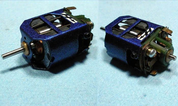
-john
#1193

Posted 10 February 2010 - 10:35 AM
Jeff Easterly
Jeff Easterly - Capt., Team Wheezer...
Asst. Mechanic, Team Zombie...
Power is coming on... NOW!!!
#1194

Posted 10 February 2010 - 12:18 PM
Slots-4-Ever
Brian McPherson
REM Raceway
"We didn't realize we were making memories, we just knew we were having FUN!"
#1195

Posted 10 February 2010 - 12:52 PM
#1196

Posted 10 February 2010 - 01:03 PM
Thanks for that.
-john
#1197

Posted 10 February 2010 - 03:46 PM
Wow - wow - wow!!! Interesting that you should paint it the exact color I had in mind - without my telling you! Ahhh, the power of thought. My wife say's "its beautiful" for a motor - LOL!! That's because it looks close to her favorite color "chinese blue".
Your workmanship is highly valued my friend - Thank you!
Ernie
#1198

Posted 10 February 2010 - 03:52 PM
Did I mention that I really really like the color!
John, What brand of aerosol paint is it from and is it called "cobalt blue" please?
Thank you.
Ernie
#1199

Posted 10 February 2010 - 04:06 PM
I'm stoked that you (and Mrs L too!) like the motor. It's a sweet runner, and as pretty much a G20 motor now will be fast but not stoopid and should hold up well. Speaking of stoopid fast, I'm working on something else for you as well
-john
#1200

Posted 11 February 2010 - 06:43 PM
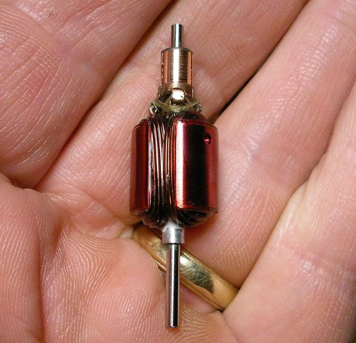
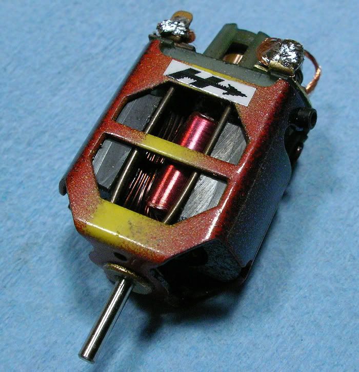
Well, I then had to do a little work on the motor as these came with the "one-up/one down" tabs and hardware and I figured there's no way that bottom lead wire tab isn't going to be in the way of something. So I made up a brush plate with a lead tab on top and left it a little tall so it wouldn't interfere with the brush spring. I centered the arm in the field of the multicolored can...fired it up...and had to close my eyes for fear of something blowing up, but it all held together pretty well
-john
- Geary Carrier likes this


 This topic is locked


