Jump to content


Photo

Arm winding #1

Closed due to length

  • This topic is locked This topic is locked
3573 replies to this topic

#2051 havlicek

havlicek

    OCD Rewinder

  • Subscriber
  • PipPipPipPipPipPipPipPip
  • 11,198 posts
  • Joined: 20-August 07
  • Gender:Male
  • Location:NY

Posted 08 November 2010 - 01:55 PM

Hi Again Mike,

Interesting. We always scraped too. Recently, I tried sandpaper without much success. Either way there's a fine line between getting the coating off and going too far and weakening the wire


I always use an X-Acto knife with a new/sharp #11 blade and it does a wonderful job. You do have to be more careful when scraping lighter-gauge wire, but then again you also have to be more careful when tensioning lighter wire when winding, so the two are alike in that way.

I'm gonna try rewinding again sometime soon. We are running "open" classes now in the club so, I have the perfect opportunity to test.


That's great and if there's any other info I might be able to help with, by all means ask! Running in an open class (unless I don't understand any specifics) might be putting you behind the 8 ball a little since there will no doubt be some people running very expensive and very fast motors. It would be cool for some track(s) to devise a "limited open" (or whatever you want to call it) class that could encourage rewinders to participate and yet still not close the door to others who might want to build motors without rewinding. I look forward to seeing your motor projects :)

-john
John Havlicek


#2052 GearBear

GearBear

    On The Lead Lap

  • Full Member
  • PipPipPipPip
  • 363 posts
  • Joined: 04-February 10
  • Gender:Male

Posted 08 November 2010 - 04:53 PM

John,

I know back in the thread somewhere you talked a little bit about how you brazed the stacks. Can you go into more detail on that? I have a couple of Bill's blanks and comms and would like to wind up something, but I'm concerned about how you go about brazing the comm connection.
Gary Johnson

#2053 32Deuce

32Deuce

    non-recovering slotaholic

  • Full Member
  • PipPipPipPip
  • 227 posts
  • Joined: 25-February 06
  • Gender:Male
  • Location:USA

Posted 08 November 2010 - 05:00 PM

might be putting you behind the 8 ball a little since there will no doubt be some people running very expensive and very fast motors


Our tracks are smaller than the commercial tracks and therefore tighter turns requiring a very seasoned driver and a great handling chassis if you choose to run a "27" or "7" or something similar so that kind of polices itself. This season it's 1/32 cars so that's a max. 2.5" wide. Next season we are talking about an open 1/24 so that may open things up a bit. The tracks are routed, with braid. I doubt you could run anything like this on plastic. It's a blast just to challenge yourself much less compete and win which at our stage of the game winning is just a bonus. It's not a necessity. I like the open format because you can do anything you wish and innovate & create to your heart's desire. I've run a different car each of the 5 races so far, all scratchbuilt except one. Different motors, chassis & setups picking the best one for that particular track. The one that wasn't scratchbuilt was a JK HC1132 or "X32." Let me tell you it was very impressive. They've done their homework on that piece. Most of the guys are running these or other lazer cut JK chassis. Only two of us are running scratch built.

You've inspired me to try rewinding again. Just something else I can try and see what happens.

Z
Mike Zimmerman
Posted Image

#2054 havlicek

havlicek

    OCD Rewinder

  • Subscriber
  • PipPipPipPipPipPipPipPip
  • 11,198 posts
  • Joined: 20-August 07
  • Gender:Male
  • Location:NY

Posted 08 November 2010 - 05:59 PM

That sounds great Mike, and if I've helped at all...I'm stoked.

-john
John Havlicek

#2055 havlicek

havlicek

    OCD Rewinder

  • Subscriber
  • PipPipPipPipPipPipPipPip
  • 11,198 posts
  • Joined: 20-August 07
  • Gender:Male
  • Location:NY

Posted 08 November 2010 - 06:03 PM

John,

I know back in the thread somewhere you talked a little bit about how you brazed the stacks. Can you go into more detail on that? I have a couple of Bill's blanks and comms and would like to wind up something, but I'm concerned about how you go about brazing the comm connection.

Hi Gary,

This is something that is a little tricky and of course (risk-avoidance mode="on") I NEVER recommend that people do what I do. So here's the basic idea, instead of using "solder" which melts at a relatively low temperature, I use a brazing process. Brazing is basically just high-temperature soldering, but the filler metal melts at a much higher temperature. I use a jeweler's silver compound that comes in a syringe with a fine metal tip...the silver is powdered and suspended in a brazing flux. I bought one small syringe like those available here and there's enough in there for probably a thousand connections (?):

jeweler's silver paste


You'll notice that it comes in different alloys labelled as "easy", "medium" and "hard". The "easy" stuff is what I use and it melts at over 1100 degrees F, plenty high enough to not have to worry about it, but safely below the melting point of brass. The other thing here is that silver is an excellent conductor of electricity, one of the best so it's well suited to electrical connections.

Now you need a power supply that can deliver beaucoup amperage at as low a voltage as you can manage (we're dealing with DC). The current will provide the "heat", the voltage really only serves to give you a spark and you don't need that here since we're not dealing with a "gap" as in arc-welding. Anyway, for a power source, I use a car-starter/battery charger. It's important to not get a regular battery charger since they won't necessarily be able to supply a lot of cranking amps. The one I got will do 55 amps @ 6V, because supplies that will do a bunch of amps at around 3V DC are expensive. The thing I got and is like this one but has the "Dayton" name (rebadged?) and is sold by Grainger:

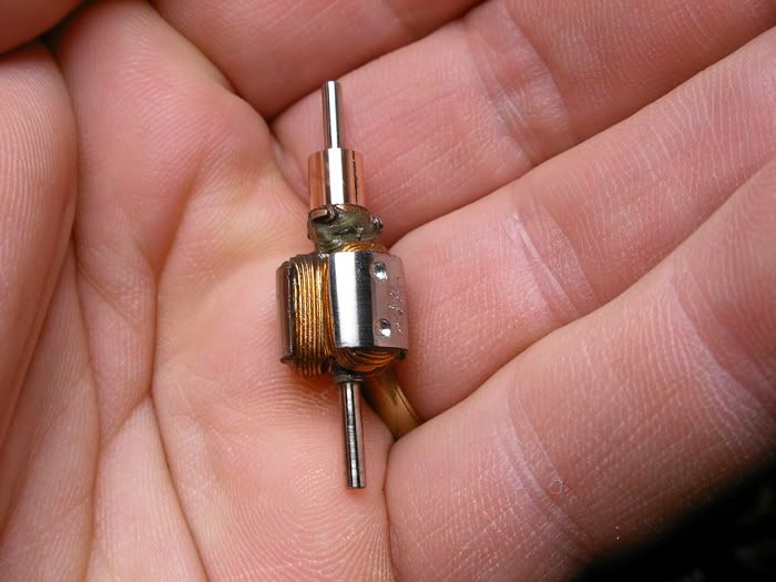
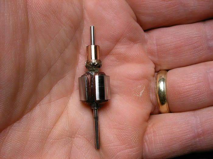
Car Starter/Charger


So now you need to be able to transfer all that current to a small spot...a commutator tab, as well as generate heat at that spot. I take the carbon core out of an old style zinc/carbon C-cell battery (it's about the right size...D cell seems too large and I haven't tried a AA) and sharpen one end to a narrow/flat "chisel point". about the width of a com tab and maybe 1/16th tall. The carbon has a lot of resistance but will pass current, exactly what you need here since when the circuit is closed the carbon rod will get hot enough to fuse the jeweler's silver in a second or two. The first few times you use the carbon, it will "boil-off" any remaining goop from the battery it came out of and thereafter heat up cleanly. Still, once you get the carbon...clean it well with a strong solvent like acetone and let it dry thoroughly...heating it up for short bursts with the car starter to burn out any remaining solvent. If there's still solvent in there when you heat it full out, it can crack, burst or even explode from the expanding solvent. For a straight tabbed com without the "hook", I shape a little groove right on the tip so it sits on the com tab without slipping off.

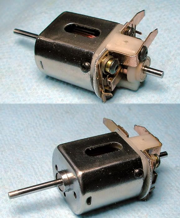
Next thing you need to do is be able to contact the carbon tip to the com tab and only after that close the circuit so the carbon heats up when you are ready for it to. To handle that much potential current, I got a 50 amp boat ignition momentary switch and mounted it in a PVC box with two brass terminals coming from each side of the switch to the top. That switch can be tripped with your foot so your hands are free. The plus side of the car starter goes to one terminal of the switch box, the other terminal goes to a piece of heavy gauge stranded wire that will carry sufficient current and has a small "battery clamp" on it's other end to hold the carbon. So the complete path from the (+) terminal of the car starter goes through the switch (single pole momentary) to the carbon brazing tip. The negative side of the car starter goes to the com segment you're brazing and to prevent the clamp from marring the com, I just fashioned a round "strap" that I slip over the com and clamp the negative from the starter over that. It's important that the com, the strap and the com tab are clean and free of corrosion so they pass current well and that the brazing bonds well.

Those are the basic components...the power supply, the "heater" (carbon) and the silver brazing metal. I'm not too comfortable going into greater detail in case someone gets hurt doing this. If any or all of the above sounds dicey, I don 't recommend you go any further. A good high-temperature solder will work on winds that aren't too crazy. The above is for entertainment purposes only!

-john
John Havlicek

#2056 GearBear

GearBear

    On The Lead Lap

  • Full Member
  • PipPipPipPip
  • 363 posts
  • Joined: 04-February 10
  • Gender:Male

Posted 08 November 2010 - 09:05 PM

John,

Excellent post! That clears up a lot of what I wanted to know. Do you think the tip for a tig welder would work in the place of your carbon rod out of the battery? Pulling a battery apart just doesn't sound like fun! :)

I actually have everything else I would need to do this but the solder paste.
Gary Johnson

#2057 havlicek

havlicek

    OCD Rewinder

  • Subscriber
  • PipPipPipPipPipPipPipPip
  • 11,198 posts
  • Joined: 20-August 07
  • Gender:Male
  • Location:NY

Posted 08 November 2010 - 09:32 PM

Hi Gary,

I don't know about the tig tip, maybe others can help in that regard. Actually, the battery thing is easy; you just cut around the battery in a circle near the end with a Dremel and after pulling it apart (like opening a can), the carbon will slip out of the goop in there. I don't know if the stuff in there is toxic, but I work from the assumption that everything I don't know about IS toxic and used disposeable gloves. It is an easy job though...easier than finding zinc/carbon batteries at this point. :) If you are going to do this, spend some time testing it all out on some scrap materials. There is some "feel" involved in knowing how long to keep the tip heating up and in contact with the tab (around 2 seconds seems about right with my setup). Also, don't twitch or you'll cause an arc to form and blow right through the com tab and the magnet wire...adios commutator.

-john
John Havlicek

#2058 Alchemist

Alchemist

    Posting Leader

  • Full Member
  • PipPipPipPipPipPipPip
  • 2,704 posts
  • Joined: 11-November 09
  • Gender:Male
  • Location:Far, far away

Posted 09 November 2010 - 08:31 PM

Hi John,

Great info again!!

If I may ask you about timing please. You had mentioned you "backed off" on the timing of my HAWK motor. How do you do that please? The next time you get to that part of the rewind, would you please consider posting photos and the steps required to "time" the motor.

I did a search on this thread but did not come across any detailed "how to" on the timing.

As always, thank you for your time John!

Ernie
Ernie Layacan

#2059 Kim Lander

Kim Lander

    Race Leader

  • Full Member
  • PipPipPipPipPip
  • 601 posts
  • Joined: 06-June 09
  • Gender:Male
  • Location:Macon, GA

Posted 09 November 2010 - 09:41 PM

John,
I have failed to ask you (cause CRS has set in), have you found that the timeing gauge I sent you is any use? Just wondered ............Kim

#2060 Bill from NH

Bill from NH

    Age scrubs away speed!

  • Full Member
  • PipPipPipPipPipPipPipPip
  • 14,806 posts
  • Joined: 02-August 07
  • Gender:Male
  • Location:New Boston, NH

Posted 09 November 2010 - 10:35 PM

Okay Kim, what did you send him? :scratch_one-s_head: I've got 3 different older timing gages, & they all work, some better than others. If in the market today for a timing gage, I'd spring for one of those sold by PRI.
Bill Fernald
 
I intend to live forever!  So far, so good.  :laugh2:  :laugh2: 

#2061 GearBear

GearBear

    On The Lead Lap

  • Full Member
  • PipPipPipPip
  • 363 posts
  • Joined: 04-February 10
  • Gender:Male

Posted 09 November 2010 - 10:47 PM

Here is the best explanation of how to time an arm and how to build your own fixture with a plain old protractor I have ever seen.
Gary Johnson

#2062 zipper

zipper

    Checkered Flag in Hand

  • Full Member
  • PipPipPipPipPipPip
  • 1,095 posts
  • Joined: 11-August 10
  • Gender:Male
  • Location:Finland

Posted 10 November 2010 - 12:07 AM

Sheesh - just like mine except my pointer is way thinner :D (and with a mirror on the back of the scale I had to diamond drill thru the glass...)
Pekka Sippola

#2063 havlicek

havlicek

    OCD Rewinder

  • Subscriber
  • PipPipPipPipPipPipPipPip
  • 11,198 posts
  • Joined: 20-August 07
  • Gender:Male
  • Location:NY

Posted 10 November 2010 - 06:23 AM

Hi Ernie,

The above protractor setup is both a good way to determine timing as well as illustrate what's going on. Basically, timing sets what the position of the poles/coils will be in the field of the permanent magnets when they are energized. Here's an illustration I did a while back to show how you can tell pretty much what the timing is of a particular armature...in this case, the arm is "neutral timed" and should spin about as fast in either direction:

Posted Image


The com tabs are centered between the pole "gap".

Here's an illustration of "advanced timing" where the com tab is no longer centered and the arm will spin faster in the direction the tab is advanced towards. The timing in the illustration will have the arm spin faster CCW when viewed from the endbell as is "standard practice" today so that a motor mounted either sidewinder or anglewinder and can drive will be spinning best in the direction you would need it to.

Posted Image


John,
I have failed to ask you (cause CRS has set in), have you found that the timeing gauge I sent you is any use? Just wondered ............Kim


Hi Kim,

Sure it's fine and is pretty much the "protractor method" and those are as accurate as anything else you're likely to use as a hobbyist. It's probably more accurate than the little timing gauges you see because the scale is bigger, so errors due to misreading the scale are reduced.

-john
John Havlicek

#2064 Alchemist

Alchemist

    Posting Leader

  • Full Member
  • PipPipPipPipPipPipPip
  • 2,704 posts
  • Joined: 11-November 09
  • Gender:Male
  • Location:Far, far away

Posted 10 November 2010 - 07:27 AM

HI,

Thanks for the link Gary. John, thanks for the explanation.

Ernie
Ernie Layacan

#2065 Afterburner Boyz

Afterburner Boyz

    Rookie Keyboard Racer

  • Full Member
  • Pip
  • 37 posts
  • Joined: 11-May 10
  • Gender:Male
  • Location:NY

Posted 10 November 2010 - 09:28 PM

So now you need to be able to transfer all that current to a small spot...a commutator tab, as well as generate heat at that spot. I take the carbon core out of an old style zinc/carbon C-cell battery (it's about the right size...D cell seems too large and I haven't tried a AA) and sharpen one end to a narrow/flat "chisel point". about the width of a com tab and maybe 1/16th tall. The carbon has a lot of resistance but will pass current, exactly what you need here since when the circuit is closed the carbon rod will get hot enough to fuse the jeweler's silver in a second or two. The first few times you use the carbon, it will "boil-off" any remaining goop from the battery it came out of and thereafter heat up cleanly. Still, once you get the carbon...clean it well with a strong solvent like acetone and let it dry thoroughly...heating it up for short bursts with the car starter to burn out any remaining solvent. If there's still solvent in there when you heat it full out, it can crack, burst or even explode from the expanding solvent. For a straight tabbed com without the "hook", I shape a little groove right on the tip so it sits on the com tab without slipping off.


I use pretty much the same setup except I use a carbon arc rod from an arc welder. They are available from any welding supply but you may have to buy a whole box which would probably last you about 10,000 or so years! You can get them individualy if you know a welder or stop by a welding shop and ask if they will sell you 1 or 2 loose ones. They have a thin copper coating on the outside of them that you can solder the high amp wire to. I bored out the inside of the metal part of an old soldering iron on my lathe to accept the carbon rod and held it in with a set screw. Then I put it back in the handle so it's real easy to hold.
John, PM me with your address and I will send you one.

-Andrew
Andrew De Santis

I AM the man from Nantucket.

#2066 havlicek

havlicek

    OCD Rewinder

  • Subscriber
  • PipPipPipPipPipPipPipPip
  • 11,198 posts
  • Joined: 20-August 07
  • Gender:Male
  • Location:NY

Posted 11 November 2010 - 07:15 AM

Hi Andrew,

I had looked at those after someone else suggested them but, as you said, I would have had to have bought a ridiculous amount for what I need. Thanks for the offer, PM sent!

-john
John Havlicek

#2067 havlicek

havlicek

    OCD Rewinder

  • Subscriber
  • PipPipPipPipPipPipPipPip
  • 11,198 posts
  • Joined: 20-August 07
  • Gender:Male
  • Location:NY

Posted 11 November 2010 - 11:55 AM

Going through the stuff that Barney sent me, I found another one of those cool little mystery cans, so I built another walnut motor...actually this one is too small to rightfully call a "walnut"...so this one is a "filbert" :) This one is almost completely made out of salvaged parts in addition to the can, the magnets are salvaged (and cut down from) a S7 mini motor, the endbell is salvaged from (and trimmed to fit) a JK Hawk, the lams are salvaged from some .480" arms I took apart earlier this week, and even the shaft has been recovered from some arms and reused here. The salvaged lams, once assembled, were polished down to get them even so the arm would up being .475" diameter when done...teensy weensy. Winding the thing meant shimming my crank with aluminum foil so I could clamp it in there. The com is one of those great Bill Bugenis pieces and I like them more and more every time I use them!...it also had to be cut down because the Hawk endbell is very short. Anyway, I did #27 wind on this one to keep it this side of ridiculous, and the stack is just a hair over .300" long :)

Posted Image


I had to cut down the motor brushes as they were interfering with the springs. The whole thing is ridiculously small for a can motor, it's really small for any motor for that matter. I again opened up the "louvred" slots it had top and bottom and also soldered in a nice tight can bushing...finishing up the setup by polishing the can and radiusing-out the inside of the brush hardware to clear the com. Oh yeah, besides cutting the length of the magnets, I also had to shim them .007" each side to tighten up the air gap. Shown here with a Mabuchi FT16D for a sense of scale:

Posted Image


While it's completely experimental and uses almost all recycled parts...and is definitely the smallest of my "mixed nuts" series :) , it surprisingly runs like a champ!

-john
  • MarcusPHagen likes this
John Havlicek

#2068 Robert V.

Robert V.

    On The Lead Lap

  • Full Member
  • PipPipPipPip
  • 350 posts
  • Joined: 14-November 09

Posted 11 November 2010 - 05:09 PM

Hi John
Wow that is small very small, i bet the drag guys would love this little motor plenty of power in a light weight package, i am curious how much does the complete motor weigh.
Robert Vaglio

#2069 havlicek

havlicek

    OCD Rewinder

  • Subscriber
  • PipPipPipPipPipPipPipPip
  • 11,198 posts
  • Joined: 20-August 07
  • Gender:Male
  • Location:NY

Posted 11 November 2010 - 05:52 PM

Hi Robert,

I don't have a scale, but the motor is extremely light. I guess it might be good for a drag car, I don't know what those guys use (I would have thought C cans) but in a light chassis it should go really well. It's going out tomorrow to be used in the future, but I don't think it'll be going in a drag car. Whatever the owner decides to put it in, it's going to be a beauty knowing his work! Posted Image

-john
John Havlicek

#2070 scolari

scolari

    Rookie Keyboard Racer

  • Full Member
  • Pip
  • 1 posts
  • Joined: 23-July 10
  • Gender:Male
  • Location:SÃO PAULO

Posted 13 November 2010 - 06:36 AM

INFORMATION

WHO it could INFORM WHICH it is THAT CEMENT BLACK WHO John RAISIN IN ARMATURE BEFORE WINDING, MARK And MANUFACTURER

THANKFUL

SCOLARI

scolari47@yahoo.com.br
Ernesto Scolari

#2071 havlicek

havlicek

    OCD Rewinder

  • Subscriber
  • PipPipPipPipPipPipPipPip
  • 11,198 posts
  • Joined: 20-August 07
  • Gender:Male
  • Location:NY

Posted 13 November 2010 - 08:14 AM

Posted Image

Hola Amigo!

The material I use is called "furnace cement" and is made by a company named "Rutland". Rutland furnace cement is available in the US tubes for around $3 or in quarts for around $10 and either is enough for thousands of armatures, but you can not buy smaller amounts. As an insulator coating for the armature it works well, but is a little fragile and can chip off if you're not careful. After epoxying, it becomes much stronger and will hold up just fine. It is verfy important that the metal is clean and has no other coatings on it when you apply the cement and to get it on evenly and neatly it should be thinned out a little with water. I use a small artist's brush to apply it, but I also round off all the sharp edges on both ends of the armature before applying the cement to make sure that you do not get any places where the armature will cut through the insulation of the wire.

Any material that will not conduct electricity, can be applied evenly to metal and will stand up to high temperatures will work fine. Maybe there is another material that you can find that will also work. I have tried different kinds of high-temperature paint and those need to be applied several times to get a thick enough coating to protect the wire. People have said also that there is a low-temperature glaze that can be used such as you put on ceramic pottery, but I could not find any that were suitable as these need to be "fired" (heated) to high temperatures in an oven to "cure". There may also be materials used in dentistry that can work, so if you're creative and look around, there may be other things out there. None of these things are as good as the coatings used by slot car motor manufacturers, but doing it that way is costly and more complicated for a hobbyist.

-john

John Havlicek

#2072 havlicek

havlicek

    OCD Rewinder

  • Subscriber
  • PipPipPipPipPipPipPipPip
  • 11,198 posts
  • Joined: 20-August 07
  • Gender:Male
  • Location:NY

Posted 13 November 2010 - 06:55 PM

Just finished-off another in my "mixed nut" series. This one is a little longer and larger (based on a Falcon mini motor)...so I guess it's a brazil nut :) I think this is something like the "Frankenmotors" that were raced, but instead of what ever arm those used , I did up a "special" #26 wind on a Mura arm assembled from salvaged .007" lams and with a new Mura com. There's no balance holes drilled in it because I couldn't balance it. It's more "balanced" than I can improve upon with static balancing. Any balancing would have to be done by sending it out for dynamic balancing, but it's really really close right as it is. That seems to happen more frequently lately for some odd reason...a run of good luck maybe.

Posted Image


Can is a cut down Falcon, and I notched the back of the magnets to move them slightly back and be able to center the arm in the field. After that, I drilled the can for retaining screws and polished it up because...well...shiny stuff just goes faster. I used an older (but mint) Mura endbell because the little bit of extra length for a full length com seemed like a good idea on such a stout wind. Trimming down the endbell to fit the Falcon can worked out really well here and it's a nice tight (but not too tight) setup for the arm:

Posted Image


Thanks to the strong magnets in these things and the seemingly really nice cans on these little motors (one piece, nice and straight and nice thick-ish metal), the field is pretty impressive and I think this wind is appropriate...although I don't think for heavy racing (?) It absolutely whistles and runs awfully smoothly proving that the balance condition is pretty danged close. This is one of the fastest of these little hot rods I've done, and definitely lighter and smaller than C-can based hot rods. I think the extra added insurance of using the Vintage Mura endbell will have been worth it! Posted Image

-john
John Havlicek

#2073 GearBear

GearBear

    On The Lead Lap

  • Full Member
  • PipPipPipPip
  • 363 posts
  • Joined: 04-February 10
  • Gender:Male

Posted 15 November 2010 - 06:46 PM

John,

You should take one of your "Nut" motors and drop it in a eurosport chassis and gear it about 7:1. Put an LMP body on it, and let'er rip!

I still haven't had a chance to do that with mine on that arm you gave me. The motor sings though! It draws about 7 amps on my power supply! I just need to grind the shaft down to 1.5mm and put it in my old Mossetti 1/24 Euro. It should be a great practice car!
Gary Johnson

#2074 havlicek

havlicek

    OCD Rewinder

  • Subscriber
  • PipPipPipPipPipPipPipPip
  • 11,198 posts
  • Joined: 20-August 07
  • Gender:Male
  • Location:NY

Posted 15 November 2010 - 07:25 PM

Hi Gary,

Funny you should mention the eurosports thing as I have had the opportunity to experiment with those lately thanks to the patience of a guy that is all about quality. The whole thing has been a real eye-opener in many ways, but it has forced me to look at how I do things more critically and I've learned some in the process. If for nothing else, I've made the first noticeable improvements in my techniques and results in probably over a year because of all this. Those eurosports motors seem completely ridiculous, like they shouldn't work at all, but they do! I forget what arm I sent you, but 7 amps sounds pretty crazy alright! These "nut" motors of course don't have the high-zoot setups and these are still using only neos from disposable mini motors, but I think they'll run OK. I think even the ones I've done in the last month or so will run better and last longer, so I'm encouraged :)

-john
John Havlicek

#2075 Victor Poulin

Victor Poulin

    Posting Leader

  • Full Member
  • PipPipPipPipPipPipPip
  • 2,097 posts
  • Joined: 04-March 08
  • Gender:Male
  • Location:Raymond, NH

Posted 15 November 2010 - 08:05 PM

Great stuff going on here as always John. You've been giving me some great ideas lol ;) But I'm not sure how you cut down the endbells and keep everything even? Is it just a matter of scribing it to the can? And once you cut it down how do you mount it, because I'm assuming you loose the mount tabs?
Inquiring minds need to know :D

Vic
Alright, who cut the cheese?


Electric Dreams Online Shop