Jump to content


Photo

Not your typical scratchbuilt chassis - a Retro mod


  • Please log in to reply
67 replies to this topic

#26 Geary Carrier

Geary Carrier

    Race Leader

  • Full Member
  • PipPipPipPipPip
  • 614 posts
  • Joined: 23-April 16
  • Gender:Not Telling
  • Location:CT

Posted 03 June 2019 - 11:23 PM

I had never posted any of my slot car projects, because I was too ashamed that my skill level would not  even register on a scale!


It's been over 10 years now, and here I am, finally coming close to completing a project, wanting to share it;  in the hopes that I would  not be too ridiculed/criticized, because of the different path of my project and workmanship.


Different paths can sometimes lead to just where you should be...


Yes, to be sure, this is it...


#27 Dave Crevie

Dave Crevie

    Grand Champion Poster

  • Full Member
  • PipPipPipPipPipPipPipPip
  • 5,096 posts
  • Joined: 16-February 09

Posted 04 June 2019 - 09:27 AM

Wow! A lot of discussion on different materials that could be used to make slot car chassis. Carbon fiber and phenolic substrates

are certainly a possibility. And with so many local libraries setting up MakerSpace departments, the availability of good CNC

router equipment, and full solid modelling software in their computer labs, this is getting to be a reality for many inventive slot

racers. Could be the future.


Incidentally, I obtained the RAM when I was working for a sub-contractor making parts for the F-22. It came in 1 m.m. thickness,

and was very flexible. I laminated three layers together to get the stiffness I wanted. I asked one of the engineers working on the

project if he knew where I could get some carbon fiber composite cheap, since the stuff from Rutan's Scaled Composites Company

was pretty pricey. He gave me the pieces, which were drop-offs from the erection floor.  


#28 Alchemist

Alchemist

    Posting Leader

  • Full Member
  • PipPipPipPipPipPipPip
  • 2,823 posts
  • Joined: 11-November 09
  • Gender:Male
  • Location:Far, far away

Posted 05 June 2019 - 06:53 PM

I decided to put a used body that I found in my misc' bin and repurpose it for testing with my prototype chassis.


I had to trim the bottom of the body a little bit, but there wasn't enough material to cut a nice sharp edge.


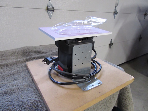
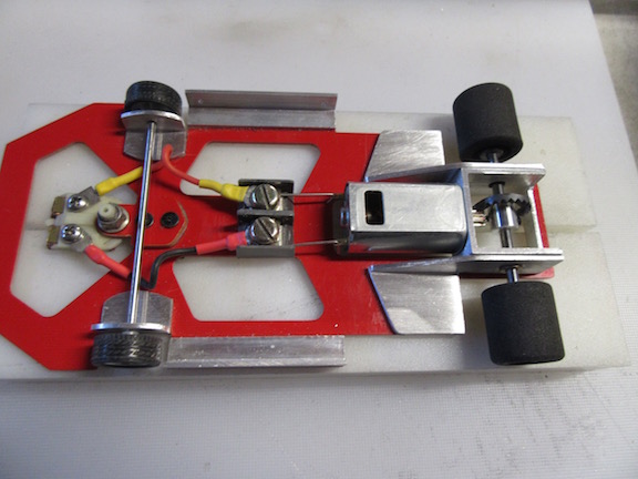
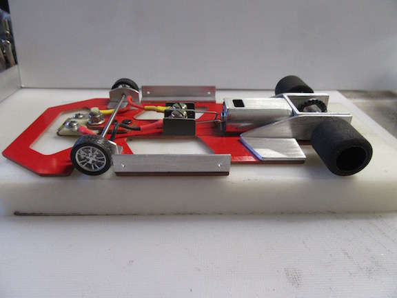
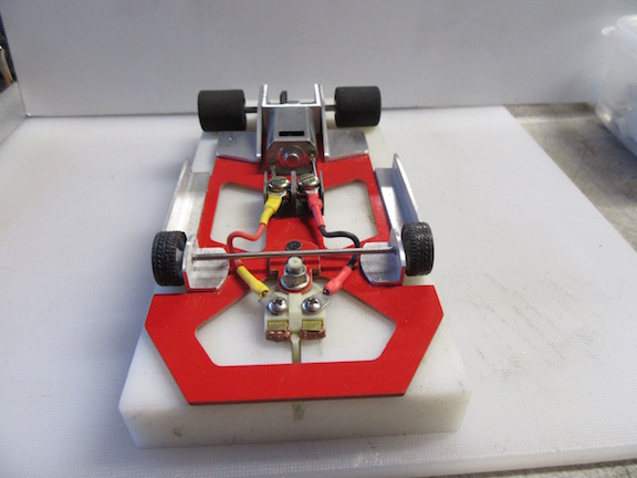
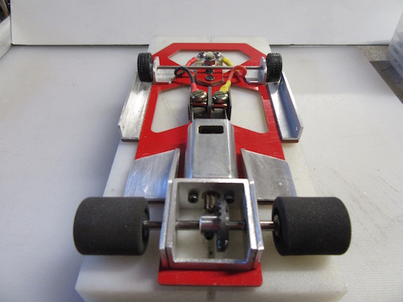
So, I pulled out my body sanding jig to trim the bottom edge and also profile a nice straight edge.


Even though I use a tape guide for trimming body bottom edges,  I can never get a nice straight edge using scissors, which is why I put this device together to assist me.


Here's a picture of sand straightening the bottom edge - of course I hold the body, but in this case, I just finished sanding.


Body Sander.jpg


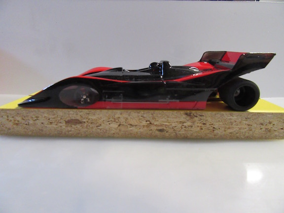
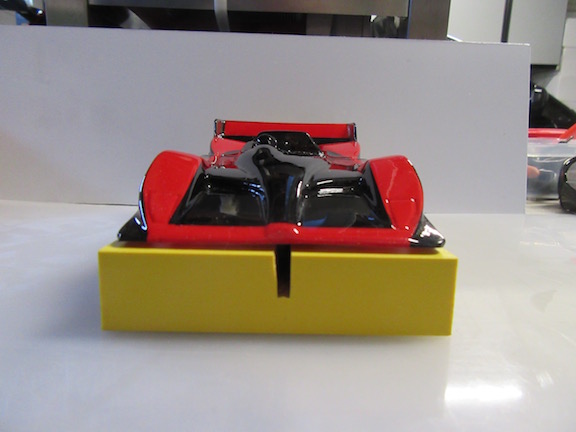
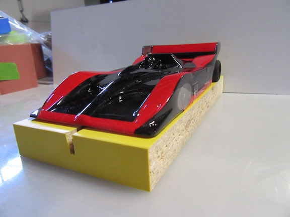
Here's a few pictures of a painted body that I used the body sander on.


Body Edge_1.jpg

Body Edge_2.jpg

Body Edge_3.jpg


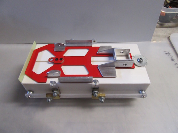
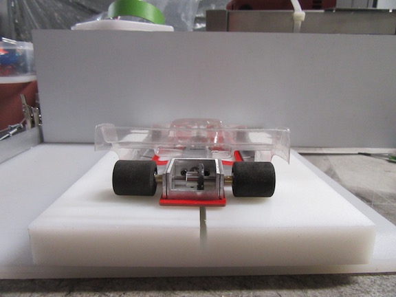
Now comes time to put new mounting holes for the body clips.


I've always had a challenge making the pin holes precisely where they need to be, and grew weary of perforating my slot car body and having it resemble a pin cushion - LOL!


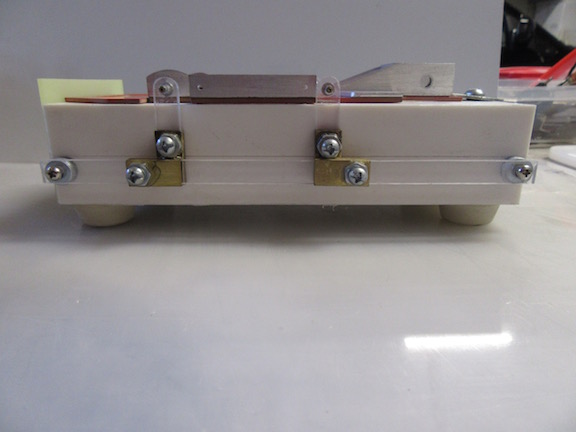
So, as an aid, I fabricated this body locating jig for precise pin hole management.


Here are a couple of photos with the chassis sitting on the body jig prior to setting it up.


Body Jig_1.jpg

Body Jig_2.jpg


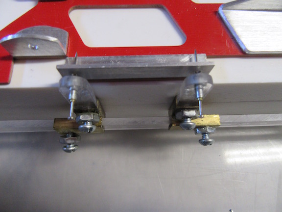
Moving the alignment fingers into place by locating the body mount bracket  pin holes, then locking it into position:


Body Jig_3.jpg


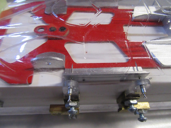
With the body in position, I then push the pin needle all the way thru the finger, body, and mounting bracket. 


Body Jig_4.jpg


Thank you.


Ernie


  • boxerdog, C. J. Bupgoo, Geary Carrier and 1 other like this
Ernie Layacan

#29 Geary Carrier

Geary Carrier

    Race Leader

  • Full Member
  • PipPipPipPipPip
  • 614 posts
  • Joined: 23-April 16
  • Gender:Not Telling
  • Location:CT

Posted 05 June 2019 - 07:31 PM

Keep em' coming Ernie, very nice indeed...


Yes, to be sure, this is it...


#30 Ecurie Martini

Ecurie Martini

    Ecurie Martini

  • Member at Peace
  • PipPipPipPipPipPip
  • 1,118 posts
  • Joined: 19-February 06
  • Gender:Male
  • Location:Baltimore MD

Posted 05 June 2019 - 10:52 PM

One of the reasons that I visit SlotBlog regularly despite the fact that my particular niche of slot racing, 1/32 (rivet counting) scale is well down the list of topics is I am always finding ideas and techniques that I can use.  I like working with laminates and machined aluminum:


gallery_99_5047_111140.jpg


gallery_99_5047_90844.jpg


The discussion on the 3M adhesives has been filed in the "Really must find an application for......." folder


EM


  • Geary Carrier likes this
Alan Schwartz
5/17/36-1/25/24
Requiescat in Pace

#31 Alchemist

Alchemist

    Posting Leader

  • Full Member
  • PipPipPipPipPipPipPip
  • 2,823 posts
  • Joined: 11-November 09
  • Gender:Male
  • Location:Far, far away

Posted 06 June 2019 - 01:46 AM

Hi Alan,


How awesome of you to share your fabrication work!


To me, the carbon fiber weave pattern, always adds so much character to the part/project - awesome Alan!


I'm also very fond of the FK180 series motors - It's so exciting to see this size

motor in 1:32 scale cars - goooo Big Block!  LOL


I'd like to share more of my experience with the use of the 3M VHB RP series tape.


A caveat in regards to any type of VHB tapes, and that is to remember that these type of tapes have a shelf life.


Actually, all adhesive tapes have a shelf life - which I discovered from many years of painting cars, motorcycles, wheels, boats, equipment, and everything else in between I was asked to paint.


It's shelf life is approximately 2 years, and that is from the time you purchase it from the store.


This information was gleaned from a 3M chemist I had the privilege of accessing, after my experience.


At times on eBay, you will find very low pricing on 3M VHB tape products, and that is because they had been sitting on the shelf for a very long time.


Some sellers may not disclose this fact, but I have seen a few sellers that do list the manufactured date - I presume if they have access to that information.


I found this out having made a large volume purchase, only to find that all the rolls I purchased, had been sagging on the roll, with the adhesive deteriorating to the point of oozing on the roll.


The adhesive properties had been compromised, so be aware if you are using it on large scale structural applications, because it will not have the tenacious adhesion one would expect when purchased recently manufactured, at your local supplier.


I've had my VHB-RP series tape rolls for longer than 2 years, but I made it a point to store them in air type plastic storage bags when not in use.  


This seems to help extend the life of the adhesive properties.


My previous batch of tape lost quite a bit of adhesive strength and had to discard them, which is why I tested a method to  determine what would happen if the tape were stored in an hermetically sealed environment - aka plastic, hermetically sealed storage bag!


It has been working for me thus far.


One must also figure in the surface area in regards to weight when using the VHB RP tape.


It won't work very well if the surface area is too small for the weight it would have to support - just some information I figured would be important.


As much as I highly regard this tape and it's uses, please do not accept my word on the VHB RP series tape. 


I highly advise reading the tech info so you can be better informed in regards to its use and application.


Thank you.


Ernie


Ernie Layacan

#32 Ecurie Martini

Ecurie Martini

    Ecurie Martini

  • Member at Peace
  • PipPipPipPipPipPip
  • 1,118 posts
  • Joined: 19-February 06
  • Gender:Male
  • Location:Baltimore MD

Posted 06 June 2019 - 08:16 AM

Many thanks for the advice and counsel on the adhesives


One thought:  I use Bare Metal Foil for some detail work.  The adhesive backing also degrades with time but the shelf life can be extended by storing it refrigerated.  I wonder if the same might be true of the 3M products?


Al


Alan Schwartz
5/17/36-1/25/24
Requiescat in Pace

#33 Alchemist

Alchemist

    Posting Leader

  • Full Member
  • PipPipPipPipPipPipPip
  • 2,823 posts
  • Joined: 11-November 09
  • Gender:Male
  • Location:Far, far away

Posted 06 June 2019 - 11:08 AM

Hi Alan,


I'm sure refrigerating the adhesive tape will definitely prolong it's shelf life.


In my Research and Experimentation (R&E), I have discovered that certain materials become stagnant below a certain temperature, which is why some products will state an appropriate ambient temperature range for maximum performance.


Since the RP tape requires a certain temperature range for the application, storing it in the fridge, from my perspective, makes for stagnating the wet-out process of bonding tape thus prolonging it's shelf life.


I would suggest you allow the tape to reach ambient temperature prior to putting it to use.


Ambient temperatures play a significant part in the bonding process.


For 3M VHB tapes, the desirable ambient tape application temperature range is 20ºC - 40ºC (68 -104 degrees Fahrenheit).


If in doubt of the substrate/surface temp, just run a hair dryer, set on high, over the surface area for a minute or two, so that it has become warm to the touch.


I typically use a hair dryer, set on the high temp, and blow hot air back and forth over the part for a minute or so.


I then touch the part to feel if it is warm to the touch, and then proceed to blow the hot air over the part once more for another minute or so.


I find that this helps accelerate the bonding process, but it still requires around 72 hours for full bond cure.


To reinforce my statement regarding shelf life, this is taken from the 3M tech sheet :


"When stored in the original cartons in cool dry conditions (ideal 20C (68 degrees) , 50% relative humidity) the shelf life is 24 months from date of manufacture."


In short, double sided pressure sensitive adhesives have a shelf life to help ensure usability and adhesive performance.


Over time, as i previously mentioned, some adhesives can become dry, brittle and lose their original performance properties. Although this occurs over time, it is helpful to have a date at which point the adhesive should no longer be used.


To reiterate, from my experiences, rolls of double sided high performance adhesive tapes can/will deform, ooze, and otherwise be very difficult to apply, despite retaining good performance relative to their stated performance levels.


In this case, a shelf life is helpful for providing a guideline for the date after which the product is unlikely to be easy to use. 


So please beware when making your purchase, should you decide to try it out!


Thank you.


Ernie


Ernie Layacan

#34 Alchemist

Alchemist

    Posting Leader

  • Full Member
  • PipPipPipPipPipPipPip
  • 2,823 posts
  • Joined: 11-November 09
  • Gender:Male
  • Location:Far, far away

Posted 06 June 2019 - 12:25 PM

Hi Alan,


On a different tangent . . . .


may I inquire as to what thickness of the CF plate you used on your 1:32 chassis please?


Also, would you or anyone be able to provide the dimensions of a 1:32 scale slot car chassis?


Wheelbase - width/length please?


What is the chassis weight of the one pictured above please?


Where did you acquire that inline motor bracket (?) please - it's a very nice piece!


Thank you.


Ernie


Ernie Layacan

#35 Alchemist

Alchemist

    Posting Leader

  • Full Member
  • PipPipPipPipPipPipPip
  • 2,823 posts
  • Joined: 11-November 09
  • Gender:Male
  • Location:Far, far away

Posted 06 June 2019 - 08:58 PM

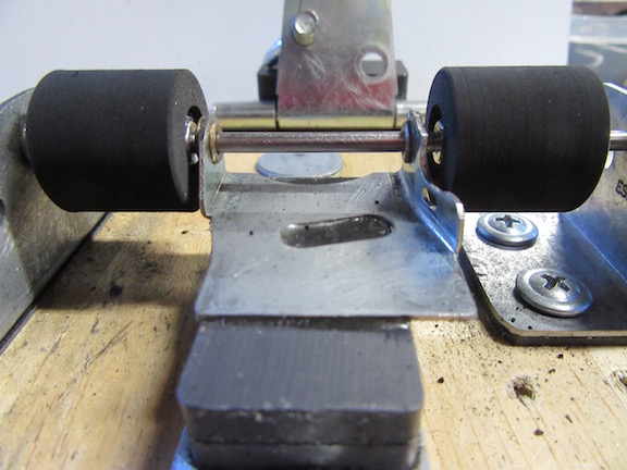
I need some fresh tires for my prototype and I have a few pairs that been around for a long time.


They are all dried out but I would like to see if they can be as fresh as new, if I cut them down.


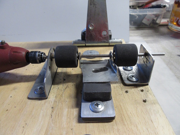
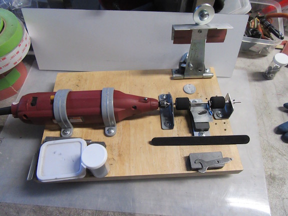
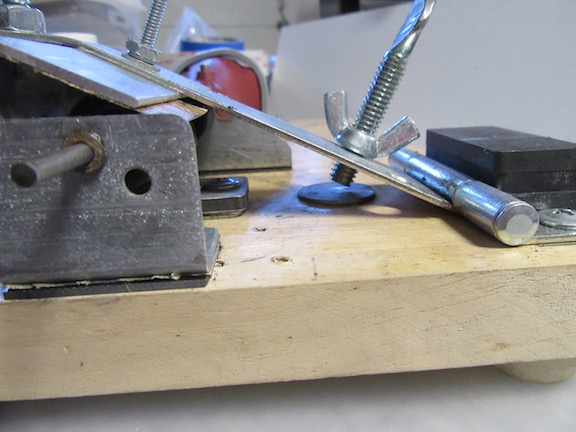
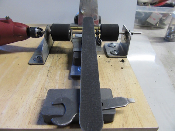
So, I pulled out my home built "tire groomer" and wanted to see how well it would work trimming the tires.


Here are the pair of tires mounted and locked in place:


Tire Cut_1.jpg


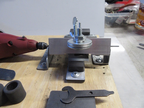
The "hood" is pulled down over the tires.  It confines the tire dust/residue in one place instead of spreading all over.


Tire Cut_2.jpg


It has a depth stop, so I can set how much material to remove.


Tire Cut_3.jpg


Here is the first cut after 20 seconds of run time:


Tire Cut_4.jpg


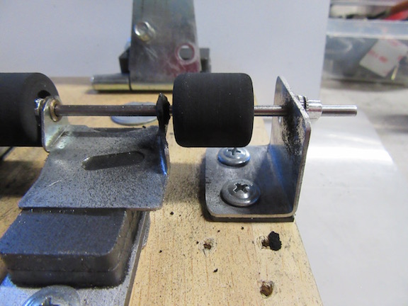
You can see the how the residue sticks to the sandpaper:


Tire Cut_5.jpg


Final cut (for now) you can see the square profile of the tires:


Tire Cut_6.jpg


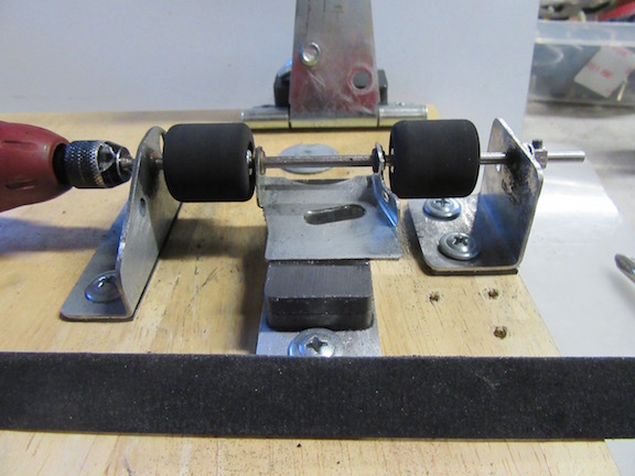
This is a paper file that I will use to profile the sides of the tires:


Tire Cut_7.jpg


One tire is profiled:


Tire Cut_8.jpg


Both tires profiled:


Tire Cut_9.jpg


This is what my tire groomer looks like - 3 speeds and all!:


Tire Cut_10.jpg


Thank you.


Ernie


  • DE38 and Geary Carrier like this
Ernie Layacan

#36 Ecurie Martini

Ecurie Martini

    Ecurie Martini

  • Member at Peace
  • PipPipPipPipPipPip
  • 1,118 posts
  • Joined: 19-February 06
  • Gender:Male
  • Location:Baltimore MD

Posted 06 June 2019 - 11:42 PM

Hi Alan,


On a different tangent . . . .


may I inquire as to what thickness of the CF plate you used on your 1:32 chassis please?


Also, would you or anyone be able to provide the dimensions of a 1:32 scale slot car chassis?


Wheelbase - width/length please?


What is the chassis weight of the one pictured above please?


Where did you acquire that inline motor bracket (?) please - it's a very nice piece!


Thank you.


Ernie


Mostly from memory:


The CF laminate is 1/16"


1/32 slot car chassis - as lawyers often say: "It depends"  Depending on era and type, probably 80% of racing cars will have a wheelbase between 88" and 102" - This particular chassis was for a BMW Group 5 car - 101" WB = 3.16" in 1/32.  Track, measured to the center of the tires, has grown over the years, from typically 46" - 48" in the 50's to 60" or more today.


Weight - don't know (and the chassis is buried in some box somewhere.  I do recall that the whole car was a bit heavier than I had hoped - a bit over 90g but then the Slot-It body was not really light.


The motor bracket and front axle/guide carrier are both scratch - machined from aluminum stock.


Thanks for your interest


Al


  • Geary Carrier likes this
Alan Schwartz
5/17/36-1/25/24
Requiescat in Pace

#37 Ecurie Martini

Ecurie Martini

    Ecurie Martini

  • Member at Peace
  • PipPipPipPipPipPip
  • 1,118 posts
  • Joined: 19-February 06
  • Gender:Male
  • Location:Baltimore MD

Posted 07 June 2019 - 08:29 AM

Wonder why above response didn't move the thread?


Alan Schwartz
5/17/36-1/25/24
Requiescat in Pace

#38 Alchemist

Alchemist

    Posting Leader

  • Full Member
  • PipPipPipPipPipPipPip
  • 2,823 posts
  • Joined: 11-November 09
  • Gender:Male
  • Location:Far, far away

Posted 07 June 2019 - 01:34 PM

Hi Alan,


Thank you for providing the information.


I really admire those aluminum pieces you fabricated - very creative design!


If I may inquire please,  as to what gear pitch/gear ratio you employ with that motor?


Is that 20 AWG wire you use for the motor?  


I'm hoping to acquire a mini lathe sometime in the near future, so I can attempt to machine some parts!


For now, I'm employing a band saw, nibbler and sanding block files - challenging but satisfying.


Thanks again Alan!


Ernie


Ernie Layacan

#39 Alchemist

Alchemist

    Posting Leader

  • Full Member
  • PipPipPipPipPipPipPip
  • 2,823 posts
  • Joined: 11-November 09
  • Gender:Male
  • Location:Far, far away

Posted 07 June 2019 - 01:50 PM


Dave Crevie said:  

Incidentally, I obtained the RAM when I was working for a sub-contractor making parts for the F-22. It came in 1 m.m. thickness,

and was very flexible. I laminated three layers together to get the stiffness I wanted. I asked one of the engineers working on the

project if he knew where I could get some carbon fiber composite cheap, since the stuff from Rutan's Scaled Composites Company

was pretty pricey. He gave me the pieces, which were drop-offs from the erection floor.  


Thanks for the reply Dave!


Ernie


Ernie Layacan

#40 Ecurie Martini

Ecurie Martini

    Ecurie Martini

  • Member at Peace
  • PipPipPipPipPipPip
  • 1,118 posts
  • Joined: 19-February 06
  • Gender:Male
  • Location:Baltimore MD

Posted 07 June 2019 - 02:35 PM

Ernie:


It's probably about a 20 ga. wire -off the shelf lead wire from Slot Car Corner.  These off-the-shelf 1/32 scale motors don't draw much current.  I routinely use Slot-It gears for in-line applications, in this case with a 1mm offset and a 2.55:1 ratio.  The Slot-It gears are a sort of hybrid design.  They are nominally about a 50DP gear but the tooth shape varies to move the contact point, the pitch diameter, in and out so they can offer different ratios with the same spacing.  For sidewinder spurs/pinions I use true 64 DP gears which are easily sourced but pinion/contrate sets are harder to find, particularly contrates  with an "inside" hub (hub on same side as teeth) needed because of space constraints in some 1/32 models like 60's F1 cars.  Sonic made some nice small contrates but they have been discontinued.


Al


Alan Schwartz
5/17/36-1/25/24
Requiescat in Pace

#41 Alchemist

Alchemist

    Posting Leader

  • Full Member
  • PipPipPipPipPipPipPip
  • 2,823 posts
  • Joined: 11-November 09
  • Gender:Male
  • Location:Far, far away

Posted 07 June 2019 - 04:30 PM

Hi Alan,


I routinely use Slot-It gears for in-line applications, in this case with a 1mm offset and a 2.55:1 ratio.  The Slot-It gears are a sort of hybrid design.  They are nominally about a 50DP gear but the tooth shape varies to move the contact point, the pitch diameter, in and out so they can offer different ratios with the same spacing.  


Wow!  That's very sophisticated from my perspective.


I've never come across this type of setup before?!


How long are the tracks (specifically the straightaway)  you run on please?


By the way, have you ever considered working with phenolic composites?


Thank you for taking the time to answer my inquires Alan!


It is appreciated.


Ernie


Ernie Layacan

#42 Alchemist

Alchemist

    Posting Leader

  • Full Member
  • PipPipPipPipPipPipPip
  • 2,823 posts
  • Joined: 11-November 09
  • Gender:Male
  • Location:Far, far away

Posted 07 June 2019 - 05:30 PM

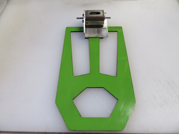
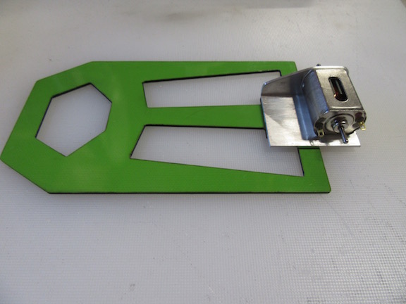
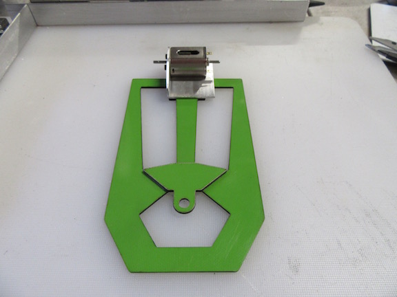
While I'm waiting for some materials to arrive in the mail, I started to sort and organize my slot car parts.


Pulling some parts from the back of the cabinet, I came across my "Direct Drive" Chassis and motor mount prototype.


Back in the later part of 2013, Mike Swiss introduced the "Direct Drive" concept.


 For years, prior to the 2013 introduction,  I had always wondered if/how a DD chassis could be designed and how well would it handle.


Mike even shared a video of the car running on the track, and how well it handled along with being eerily quiet.


Mike - I've searched for that video you posted but cannot find it anywhere - is it still available somewhere please?


By the way, I wanted to wish Mike Swiss a belated (November 2018):

Slot Car Racer of the Year – Mike Swiss      https://www.modelcar...ear-mike-swiss/


Even our illustrious Sir John Havlicek was inspired to build a Hawk DD setup, using 3/32" diameter armature shaft, instead of the usual 2mm.


Here's a photo that Sir John posted of the DD setup - which, by the way, I was fortunate to acquire from John:


DirectDriveHawk.jpg


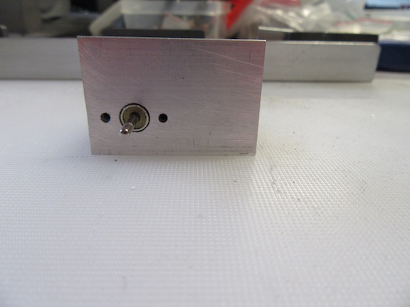
Well, I was thrilled to watch that video, and was inspired to make an effort to fabricate my own version of the DD chassis setup.


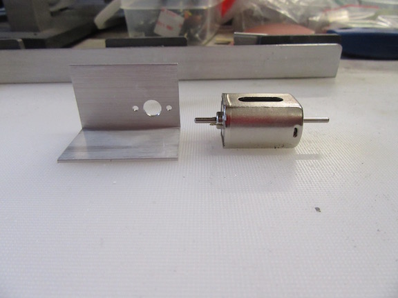
Taking the usual 6063-T5, angle aluminum I like to work with, I cut and drilled the motor bolt pattern:


Direct Drive_1.jpg


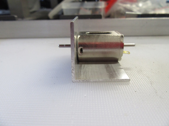
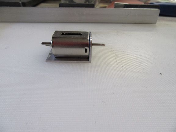
Checking motor placement and fitment:


Direct Drive_2.jpg

Direct Drive_3.jpg


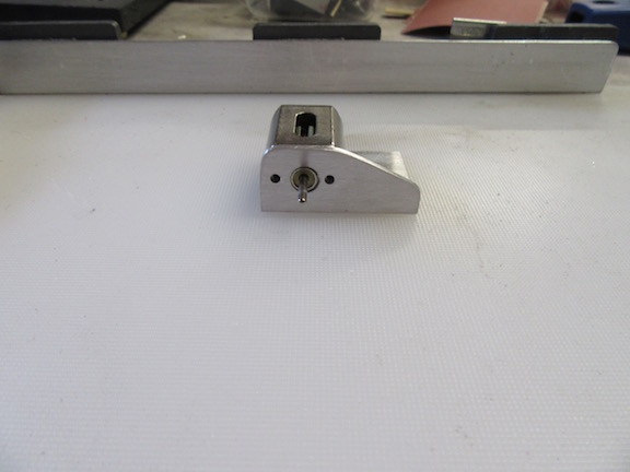
Then I took my nibbler and sandpaper file to shape the mount:


Direct Drive_4.jpg


Checking fitment again, and how it appears aesthetically, but still requires more reconfiguration:


Direct Drive_6.jpg

Direct Drive_5.jpg


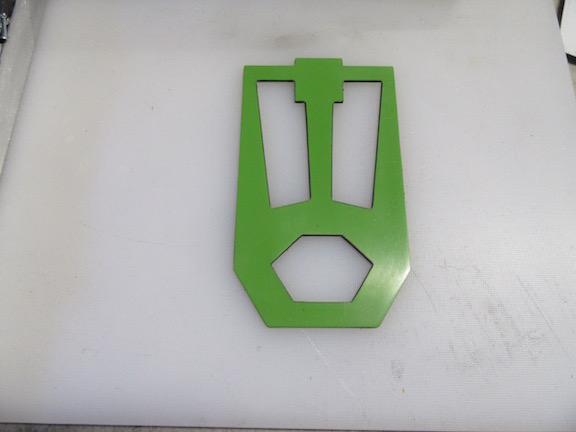
I used phenolic G10 as the chassis material, in .032 thickness, again cutting/shaping with my nibbler and sandpaper files:


Direct Drive_7.jpg


Motor mount/motor placed on the chassis:


Direct Drive_8.jpg

Direct Drive_9.jpg    This is all I've done with the motor bracket thus far, and I'm cognizant the motor bracket needs further redesign/reconfiguration.


Guide tongue installed:


Direct Drive_10.jpg


Eventually, I'll get back to working on this DD prototype chassis, but at this time I just wanted to share what I had been working on some years ago.


Thank you.


Ernie

  • MSwiss and Geary Carrier like this
Ernie Layacan

#43 don.siegel

don.siegel

    Grand Champion Poster

  • Subscriber
  • PipPipPipPipPipPipPipPip
  • 5,954 posts
  • Joined: 17-February 06
  • Gender:Male
  • Location:Paris, France

Posted 07 June 2019 - 05:34 PM

Just found this thread Ernie - congrats, you do great work! 


I'm more of a soldering guy, but your experimentation on these materials is really inspiring... hmm, I work as an aerospace translator, wonder if I can ask my customers for some ceramic matrix composites? 


Don 


#44 Alchemist

Alchemist

    Posting Leader

  • Full Member
  • PipPipPipPipPipPipPip
  • 2,823 posts
  • Joined: 11-November 09
  • Gender:Male
  • Location:Far, far away

Posted 07 June 2019 - 06:29 PM

Greetings Don,


How are you doing?  Hope all is well in Pair-eee!


Thank you so much for the kind words.


I'm more of a soldering guy, but your experimentation on these materials is really inspiring... hmm, I work as an aerospace translator, wonder if I can ask my customers for some ceramic matrix composites? 


Yes - please do ask them Don!


What size pieces of composite would you consider working with please?


Would you be working in 1:32 or 1:24 scale please?


I would like to find out how it is to work with CMC  - if you're able to acquire that material Don, do share some photos please!


It's good to hear from you!


Thank you again Don!


Ernie


Ernie Layacan

#45 Ecurie Martini

Ecurie Martini

    Ecurie Martini

  • Member at Peace
  • PipPipPipPipPipPip
  • 1,118 posts
  • Joined: 19-February 06
  • Gender:Male
  • Location:Baltimore MD

Posted 07 June 2019 - 09:17 PM

Hi Alan,


How long are the tracks (specifically the straightaway)  you run on please?


Ernie


This is our longest local track - the main straight is perhaps 25'


gallery_99_85_101239.jpg


The others are shorter - from 12' to perhaps 16'


Al


  • Geary Carrier likes this
Alan Schwartz
5/17/36-1/25/24
Requiescat in Pace

#46 Alchemist

Alchemist

    Posting Leader

  • Full Member
  • PipPipPipPipPipPipPip
  • 2,823 posts
  • Joined: 11-November 09
  • Gender:Male
  • Location:Far, far away

Posted 07 June 2019 - 09:53 PM

Hi Alan,


That track looks to be a good challenge, and I'm sure everyone has lots of enjoyment driving on it!


Wonderful track.


Thanks for sharing the photo Alan!


Ernie


Ernie Layacan

#47 Alchemist

Alchemist

    Posting Leader

  • Full Member
  • PipPipPipPipPipPipPip
  • 2,823 posts
  • Joined: 11-November 09
  • Gender:Male
  • Location:Far, far away

Posted 09 June 2019 - 09:40 PM

Time to finish up this project of mine!


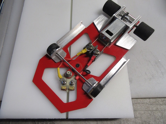
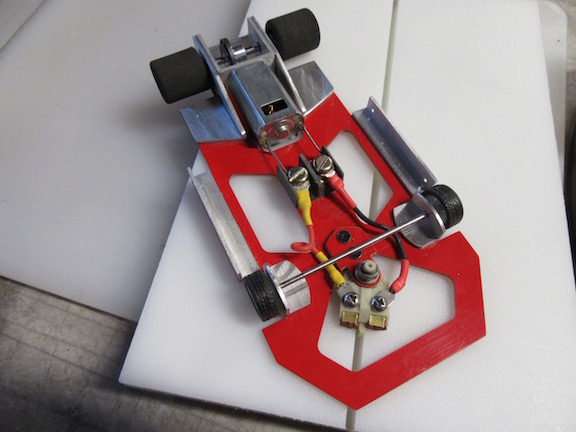
It's taken a little bit of imagineering to come up with a configuration design for my wire lead setup.


I've always admired the TSRF slot cars, specifically the way it was designed to employ contact rails to supply current to the motor.


I've also had this fascination with terminal connector blocks, wanting to configure a way to use it on a scratchbuild chassis.


So, I decided to employ these two aspects in my lead wire configuration.


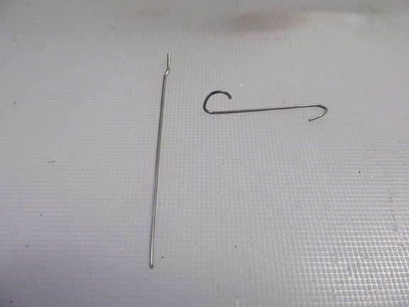
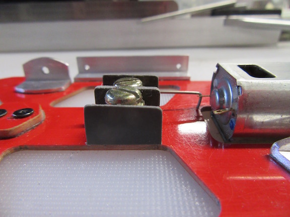
I'm using .031 stainless steel spring wire:


 Wire Lead Setup_1.jpg


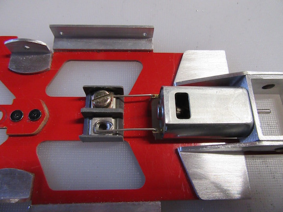
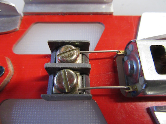
I bent the wire so that when the screws are tightened down on the terminal block, it will apply constant pressure to the spring wire thus preventing it from vibrating out of the motor terminal connector holes.


Though it may not look like it, I had to "whittle away" quite a bit material from the terminal block, to drop the connector height to almost the same level of the motor lead tabs.


Yes, I used the 3M VHB RP tape to mount the terminal block!


Wire Lead Setup_2.jpg


Here's a picture of how the spring wire was bent:


Wire Lead Setup_3.jpg


Both spring wire connectors in place:


Wire Lead Setup_4.jpg


20 AWG silicone jacket wire installed with Fork terminal connectors (I had to modify these also):


Wire Lead Setup_5.jpg


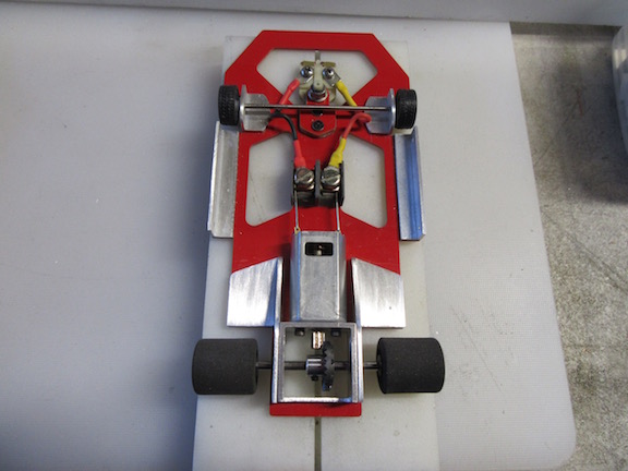
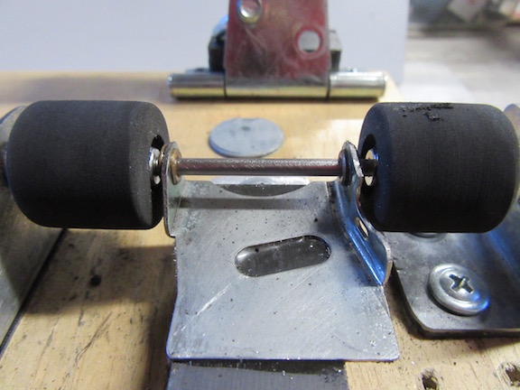
I mocked up the rear axle, pinion/crown gears, and rear wheels.  I need to determine what material I will use for the axle spacer;  brass, nylon, etc., as well as grooming new tires :


Wire Lead Setup_6.jpg

Wire Lead Setup_7.jpg

Wire Lead Setup_8.jpg

Wire Lead Setup_9.jpg


I'll finish up mounting the body, as well as the other details,  then make the hour plus drive to Fast Track Hobbies in Rocklin, California for testing.


For those wondering if there is enough slack in the lead wires, here's picture showing that.


In fact, I attempted to place the chassis at full lock, but it would not stay in place. 


It kept wanting to return to center due to the tension of the lead wires, which is why you'll see the guide a bit away from full lock.


Wire Lead Setup_10.jpg

Wire Lead Setup_11.jpg


Thank you.


Ernie

  • SpeedyNH, Geary Carrier and Jaeger Team like this
Ernie Layacan

#48 Alchemist

Alchemist

    Posting Leader

  • Full Member
  • PipPipPipPipPipPipPip
  • 2,823 posts
  • Joined: 11-November 09
  • Gender:Male
  • Location:Far, far away

Posted 09 June 2019 - 10:53 PM

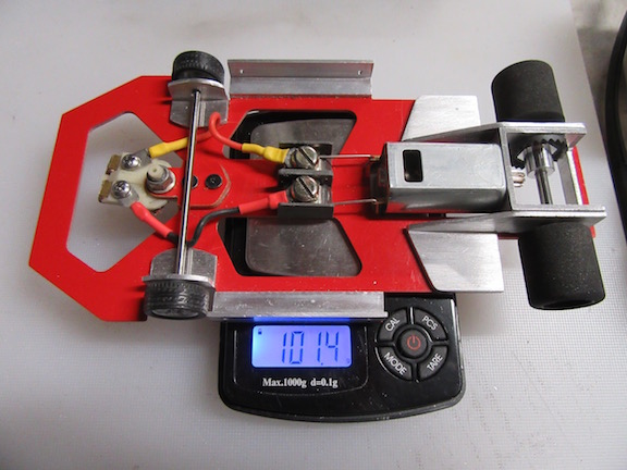
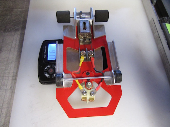
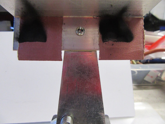
With the FK-180 motor, it weighs in at:


Wire Lead_Weight_Assembled.jpg


Thank you.


Ernie

  • Geary Carrier likes this
Ernie Layacan

#49 Alchemist

Alchemist

    Posting Leader

  • Full Member
  • PipPipPipPipPipPipPip
  • 2,823 posts
  • Joined: 11-November 09
  • Gender:Male
  • Location:Far, far away

Posted 10 June 2019 - 04:11 PM

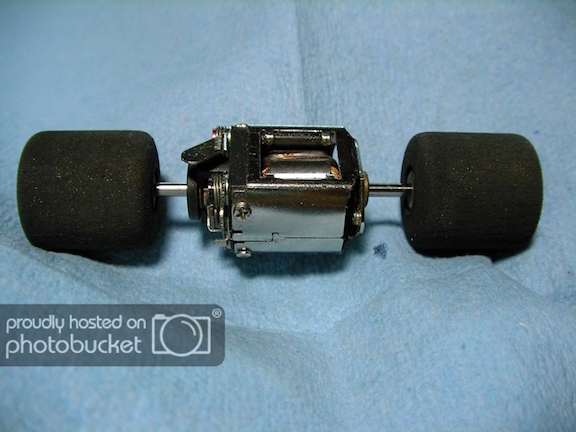
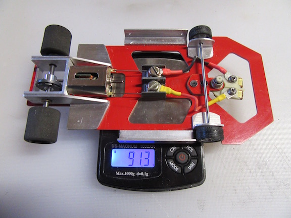
As I was sorting thru some items, I came across an old JK Hawk Retro Motor.


Then a thought came to mind, why not post a photo of my "RetroMod Chassis with a Retro Motor!"


I had to reconfigure a couple of longer contact wire clips.


It also does not have a pinion gear, but you can see the difference, both in weight and motor appearance on the chassis.


Wire Lead_Retro Hawk Motor_1.jpg

Wire Lead_Retro Hawk Motor_2.jpg


Hope you enjoy the pictures.


Thank you.


Ernie

  • boxerdog, SpeedyNH, Geary Carrier and 1 other like this
Ernie Layacan

#50 Alchemist

Alchemist

    Posting Leader

  • Full Member
  • PipPipPipPipPipPipPip
  • 2,823 posts
  • Joined: 11-November 09
  • Gender:Male
  • Location:Far, far away

Posted 14 June 2019 - 01:20 PM

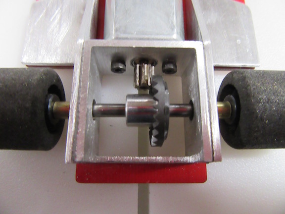
I cut the brass axle spacers and mounted the crown gear.


I decided on a  3:1 gear ratio as a starting point, employing an 8 tooth pinion with a 24T crown gear.


As I got started with slot cars during the 60's, the 8 tooth pinion was the only pinion I  used . . .  Why?  Because my cousin gave them to me for free - LOL!


RTR_1.jpg

If you take a close look at the motor box and brackets, you'll see evidence of the 3M RP bonding tape between the two parts.


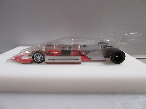
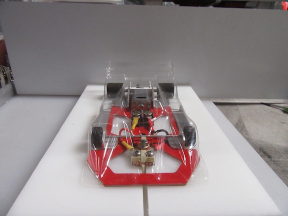
Body is retrofitted and about ready to go testing - just need to finish "grooming" an old pair of rear tires to the appropriate diameter.

RTR_2.jpg

The body is not rigid mounted.       The wire body clip setup allows enough body movement to  "Shake, Rattle and Roll".  LOL


I also did not mention it previously, but I've always liked the front wheels of my car to touch the track, and my front wheel arrangement allow them to "float".


RTR_3.jpg

RTR_5.jpg


Thank you.


Ernie

  • Geary Carrier likes this
Ernie Layacan


Electric Dreams Online Shop