-john

Jerry Hansen's 1966 Lotus 19 Chevy
#51

Posted 06 September 2009 - 12:45 PM
-john
#52

Posted 07 September 2009 - 12:46 PM
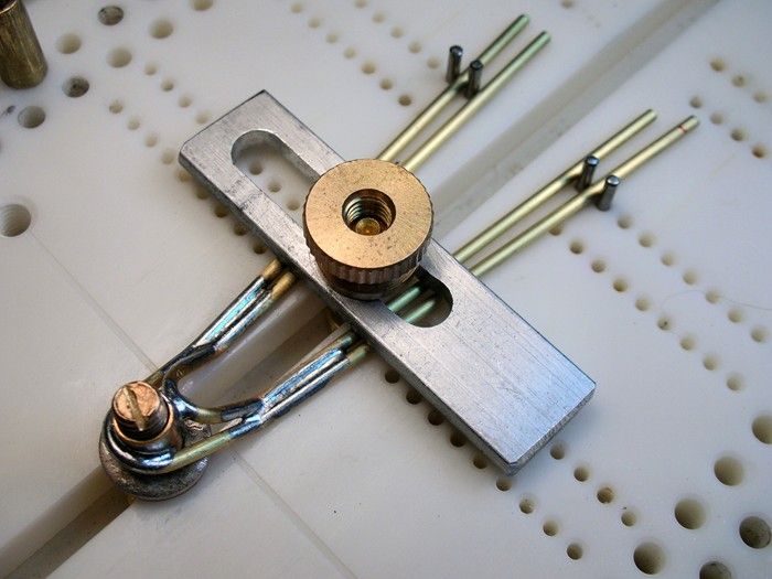
...........and install it in the chassis:
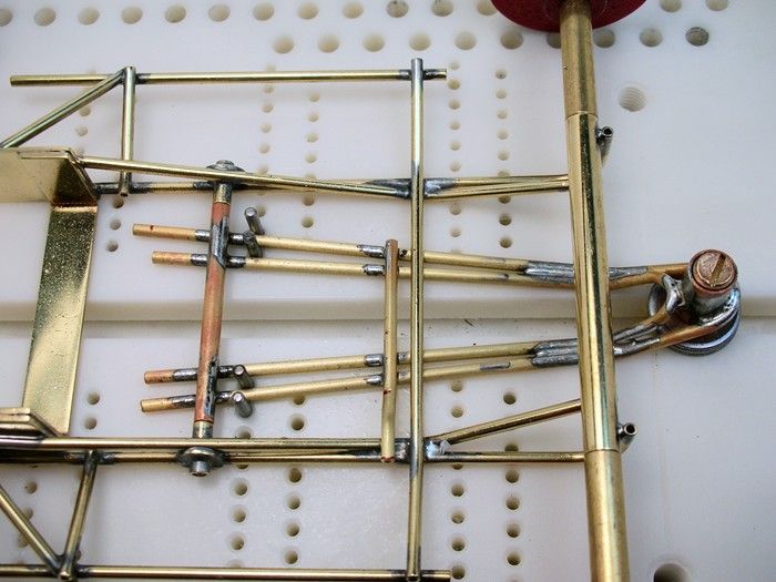
The chassis is all finished:
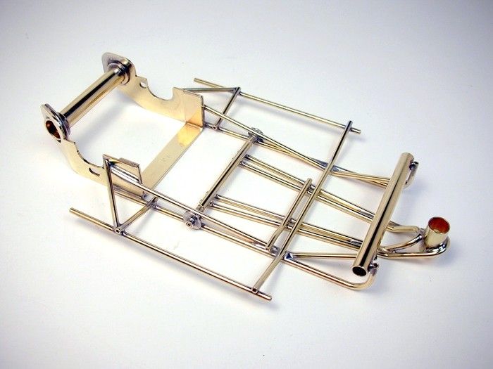
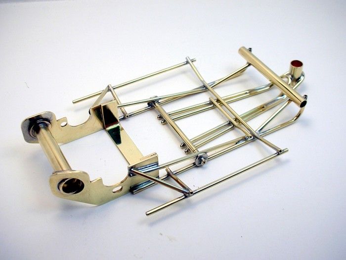
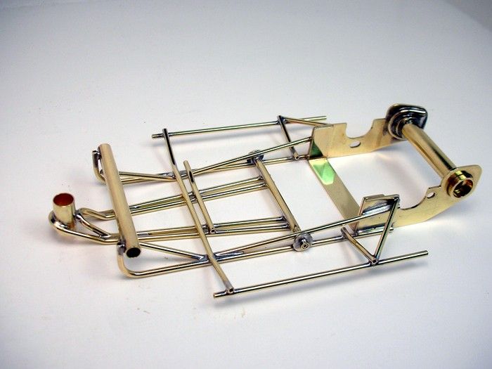
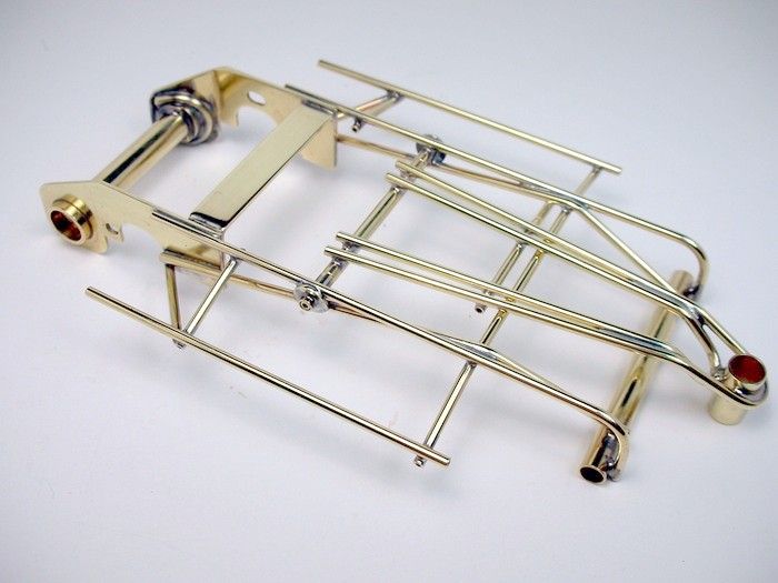
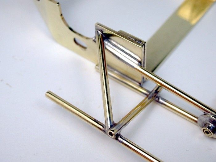
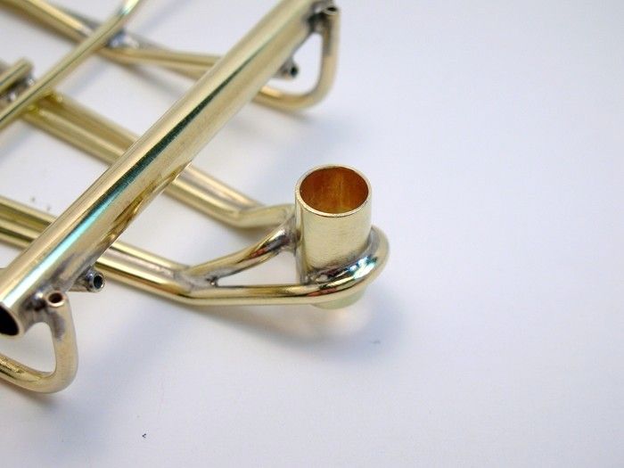
A few closeups:
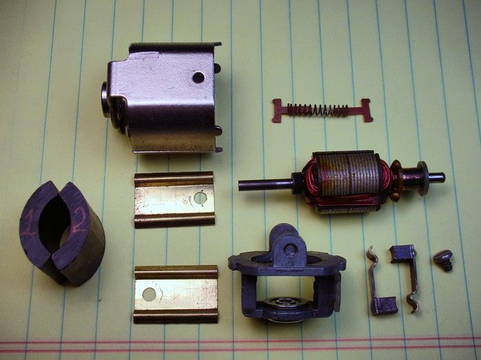
Time to tear apart that old Pittman motor
- slotbaker and hiline2 like this
Rick Thigpen
Check out Steve Okeefe's great web site at its new home here at Slotblog:
The Independent Scratchbuilder
There's much more to come...
#53

Posted 07 September 2009 - 01:41 PM
Philippe de Lespinay
#54

Posted 08 September 2009 - 03:23 PM
amazing stuff
#55

Posted 08 September 2009 - 03:50 PM
Anthony 'Tonyp' Przybylowicz
5/28/50-12/20/21
Requiescat in Pace
#56

Posted 08 September 2009 - 05:02 PM
I tore my Pittman 6001 apart last night. I'll post pictures of the carnage tonight.
Rick Thigpen
Check out Steve Okeefe's great web site at its new home here at Slotblog:
The Independent Scratchbuilder
There's much more to come...
#57

Posted 08 September 2009 - 09:10 PM
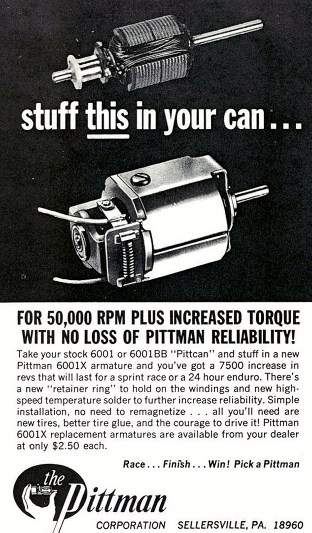
Mine is a later motor as it already has the hot armature (.4 ohms) shown in this ad:
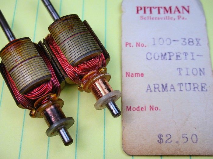
Here's a comparison of my arm on the left with a new 6001X arm on the right:
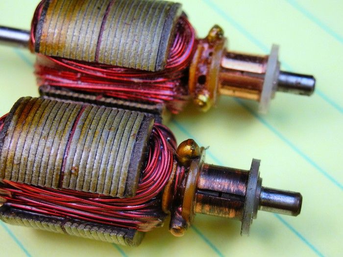
Hey John Havlicek. This arms got an insullator in the middle of the stack
I also want to fix the bone head move I did to melt the brush spring, plungers and mar this brush plate:
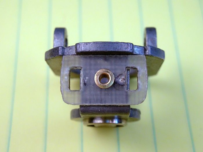
Next up it's "Mod City" for the old "Sellersville Slayer"
Rick Thigpen
Check out Steve Okeefe's great web site at its new home here at Slotblog:
The Independent Scratchbuilder
There's much more to come...
#58

Posted 08 September 2009 - 09:30 PM
Oops, by the way, nice build! I've never had one (Pittcan) apart before.
My life fades, the vison dims. All that remains are memories... from The Road Warrior
#59

Posted 09 September 2009 - 09:47 AM
I found this one on Ebay a few months ago. It's an early hot "competition" arm with the "X" designation in the part number. I've got another one in later packaging that's designated a "6 Volt". I'll show pictures of both and check out their ohm readings and eyeball their timing etc tonight.
Rick Thigpen
Check out Steve Okeefe's great web site at its new home here at Slotblog:
The Independent Scratchbuilder
There's much more to come...
#60

Posted 09 September 2009 - 12:08 PM
Mikey
Mike DiVuolo
C.A.R.S. Vintage Slot Car Club
"Prosecutors will be violated"
#61

Posted 09 September 2009 - 09:33 PM
I dug up my other packaged 6001 armature. I thought since it was a "6 volt" it would be the newer bad a$$ replacement arm in the ad I posted. Wrong again
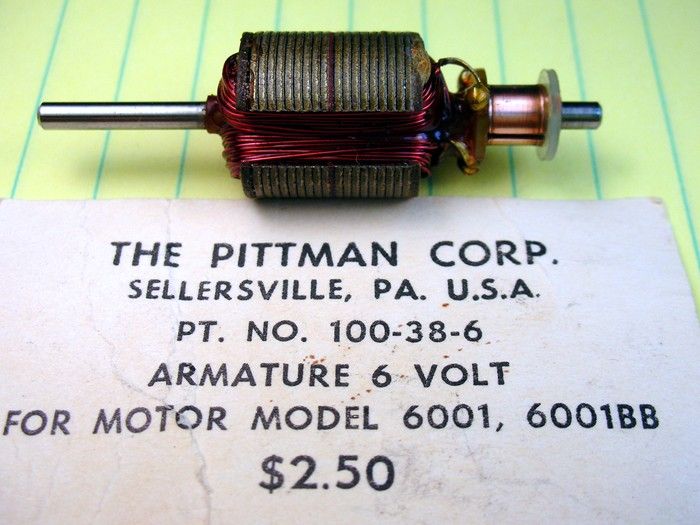
It's a double wind with the wires to the comm in sacrificial readiness to throw themselves to the magnet Gods without the competition models "retainer ring":
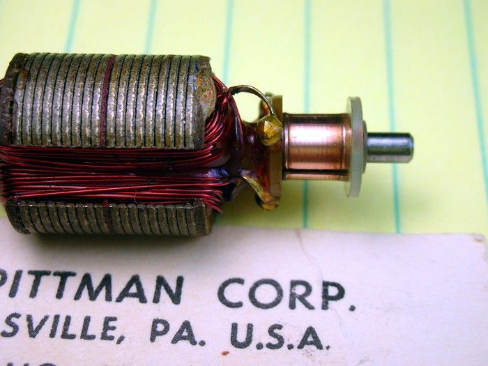
The timing is also reversed from the "competition armature"
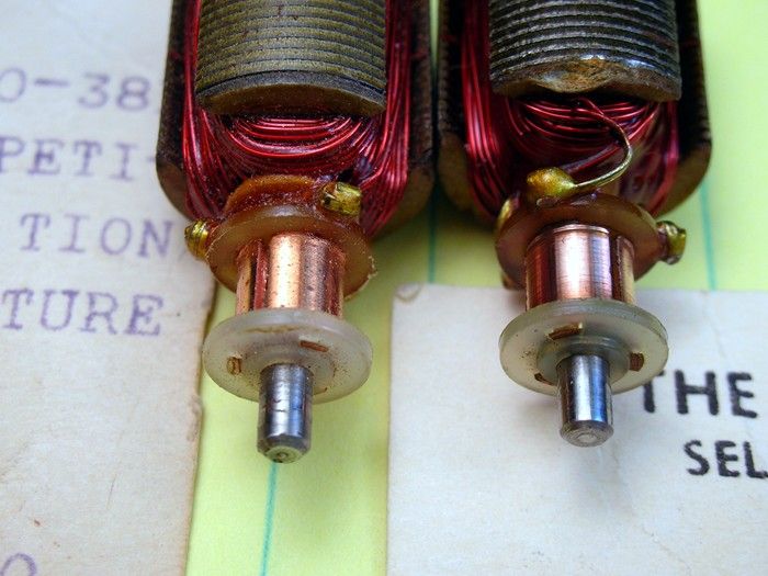
The "competition arm" reads .4 ohms and the "6 volt" reads .6 ohm.
Gary,
Now I know why you've been looking for a "competition" style arm!
Rick Thigpen
Check out Steve Okeefe's great web site at its new home here at Slotblog:
The Independent Scratchbuilder
There's much more to come...
#62

Posted 10 September 2009 - 06:02 AM
Hey John Havlicek. This arms got an insullator in the middle of the stack
Yeah I saw that and I'll tell you what, it defies logic to think that they simply did this to decrease the rotational mass of the arm as was suggested in another thread. Substituting one lam for a fiber insulator isn't going to change things significantly performance-wise. If they DID do it for that reason, then they were being silly and probably never tested it...OR they did test it and did it that way only because it was "percieved" to be lighter/faster by the "market"
-john
#63

Posted 10 September 2009 - 12:18 PM
A few years ago, aftermarket group 10 "stock" arms came from a couple people with thin groove longetudinally down the stack purportedly for the same purpose. I don't say any of these assertians are true, just reporting what was said!
I agree, it doesn't make sense!
As we have both observed about these motors, lots of "improvements" have been done over the years and I haven't seen a decent way to test. It always devolves to the track.
fate
3/6/48-1/1/12
Requiescat in Pace
#64

Posted 10 September 2009 - 01:24 PM
In RC we leave spaces in the stack to get around the spec rules that called for a minimum amout of wire length for 27 turns. The wire had to be 62" and 27 turns so a short stack was out of the question. It makes a difference where the spaces are put in armature performance. The motors are way less eficient but put out a lot more watts and are faster which in spec racing is a big advantage.
We also made a blank with a slot down the center. The real reason was simply to make it easier to drill balance.
A lot of the 60's,"Technology" was hit and miss. People would try anything they could think of no mattery how crazy it was. A lot was simply a gimmick to make your stuff look different and trick.
Anthony 'Tonyp' Przybylowicz
5/28/50-12/20/21
Requiescat in Pace
#65

Posted 10 September 2009 - 03:14 PM
I hope you haven't lost your accent already...wear it loud and proud down there
A lot of the 60's,"Technology" was hit and miss. People would try anything they could think of no mattery how crazy it was. A lot was simply a gimmick to make your stuff look different and trick.
10-4, I miss those days
-john
- Jocke P likes this
#66

Posted 12 September 2009 - 05:12 PM
My life fades, the vison dims. All that remains are memories... from The Road Warrior
#67

Posted 12 September 2009 - 07:30 PM
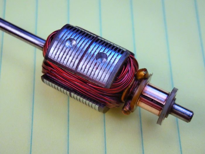
Next I worked on the endbell. In lots of the old "Hop Up" articles in the period magazines they'd drill holes in things.....anything! If there was room for a hole, it got a hole
I thought I show how and accurately located and sized hole is created with a milling machine. But first, a DISCLAIMER:
I know there are experienced hobbyist, machinists and tool and die makers (Hi Duffy
So here is the endbell in the milling machine vise. The gizmo in front of it is an edge finder. It happily spins as you move the endbell closer and closer......
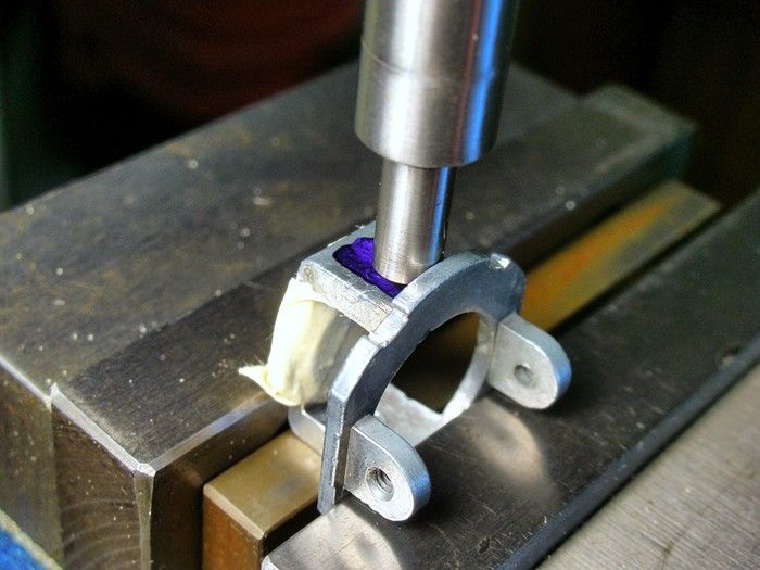
.........and when the bottom part jumps off center you've located the edge of the part:
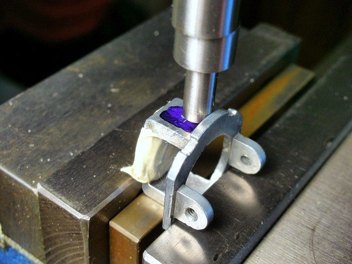
Then the milling machines adjustable dials are turned the correct distance to locate the hole from the edge you just "edge found". With the endbell located exactly where the hole should go a pilot hole is drilled with a stiff special purpose drill called a center drill:
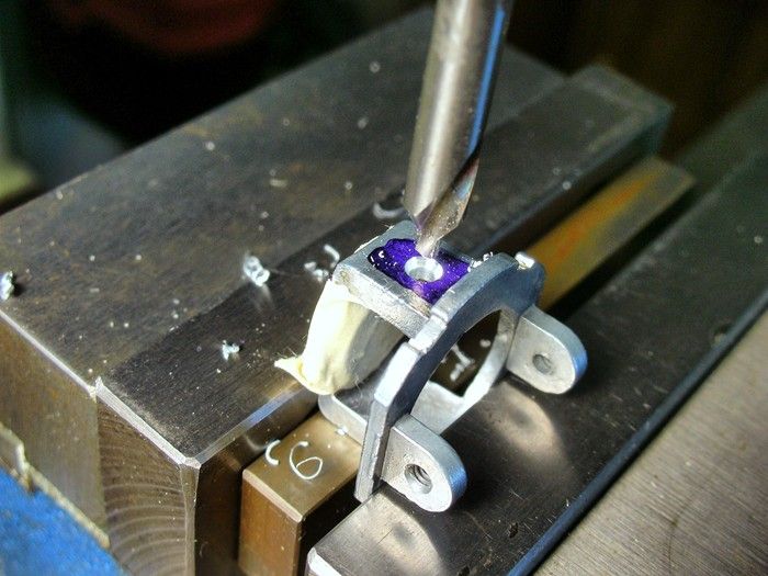
A pilot hole helps keep the standard drill from wandering off center:
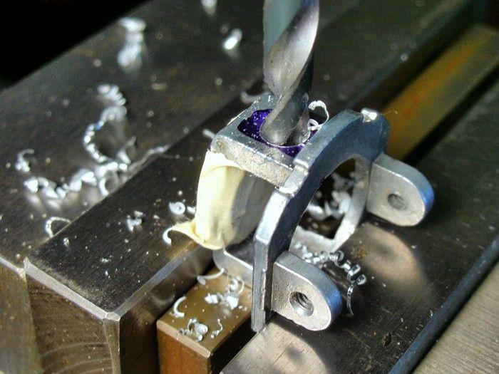
Drills often don't leave that nice a finish on the sides of the hole. I finished this one off with and end mill. Since the end mill cuts on the sides too it acts like a boring operation and insures the hole will be on center even if the drill (which just cuts on its tip) did somehow wander off:
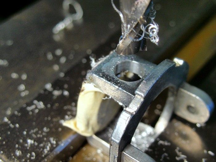
Finally a countersink makes a an nice deep chamfer to make the hole purdy:
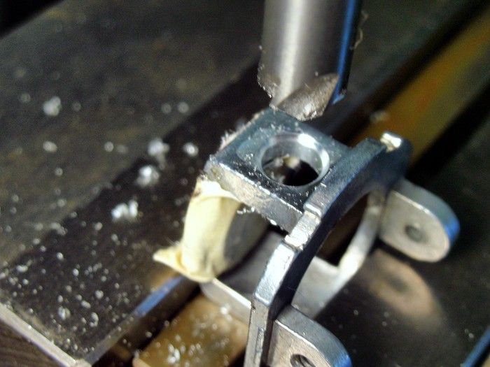
The finished hole......hey what's that nut doing in there
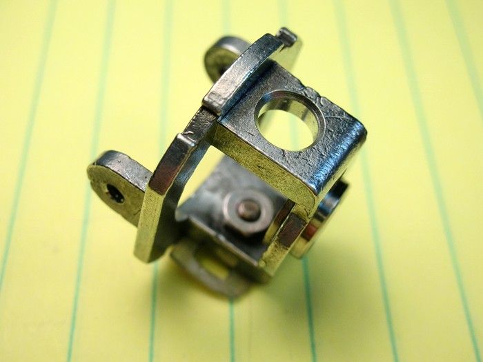
I drilled out the brass rivet that held the brush plate on so I could flip it over and hide the burn marks my bone head move put in it. Here are all the parts for the modified endbell:
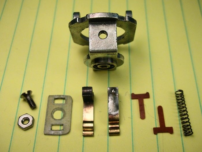
I used a 2-56 flat head stainless steel screw, nut and some red thread locker to hole the brush plate on:
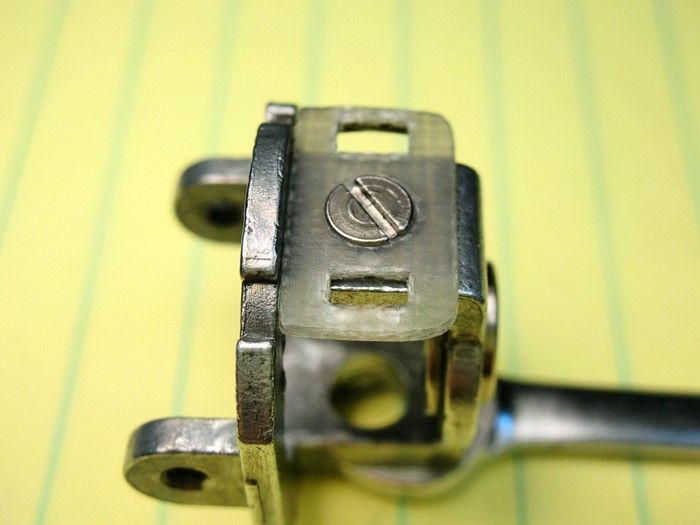
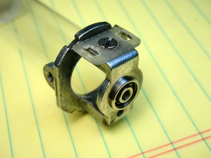
The finished endbell:
Time to epoxy the magnets into the can..........
Onward
- hiline2 likes this
Rick Thigpen
Check out Steve Okeefe's great web site at its new home here at Slotblog:
The Independent Scratchbuilder
There's much more to come...
#68

Posted 12 September 2009 - 07:55 PM
Just asking.... beautiful work! I have done the same thing regarding the brush holder. Sometimes replacing a broken one with screw... but I threaded the end bell, which eliminates the nut. But beautiful work!
(I need a mill!)
Jairus H Watson - Artist
Need something painted, soldered, carved, or killed? - jairuswtsn@aol.com
www.slotcarsmag.com
www.jairuswatson.net
http://www.ratholecustoms.com
Check out some of the cool stuff on my Fotki!
#69

Posted 12 September 2009 - 07:59 PM
I love Dremel wire wheels
If the hole in the endbell wasn't already so big I'd have just tapped the thing. But, I'd have to use a No.4 screw and it was SO big looking I went with a smaller No.2 screw and a nut.
Yes, you do need a mill
Rick Thigpen
Check out Steve Okeefe's great web site at its new home here at Slotblog:
The Independent Scratchbuilder
There's much more to come...
#70

Posted 12 September 2009 - 08:06 PM
Jairus H Watson - Artist
Need something painted, soldered, carved, or killed? - jairuswtsn@aol.com
www.slotcarsmag.com
www.jairuswatson.net
http://www.ratholecustoms.com
Check out some of the cool stuff on my Fotki!
#71

Posted 12 September 2009 - 10:10 PM
Onward
Rick Thigpen
Check out Steve Okeefe's great web site at its new home here at Slotblog:
The Independent Scratchbuilder
There's much more to come...
#72

Posted 12 September 2009 - 11:59 PM
(Hi yerself RickI know there are experienced hobbyist, machinists and tool and die makers (Hi Duffy
) looking in.
We "Experienced" toolish guys have a wise old saying: "What Works, Works."
Duffy
1950-2016
Requiescat in Pace
And I am awaiting
perpetually and forever
a renaissance of wonder
#73

Posted 13 September 2009 - 09:12 AM
I balanced the arm on my Tradeship static balancer. The heavy pole swung down so fast I couldn't believe it.
Hey Rick,
Did you check the shaft for runout? Usually when an arm is that far out, it's the shaft. The most significant part of the weight equation is the stuff farthest from the axis of rotation (shaft), like the actual laminations and the magnet wire. If the winding is pretty close to the same length on each pole, the lams use usually pretty close on their own since they're just stamped metal. Another VERY cool project!
-john
#74

Posted 13 September 2009 - 05:45 PM
John,
I put the arm in a 3/32 collet in my Sherline lathe and ran it slowly. There is a slight run out. I slid the arm in and out of the collet and ran it at different positions. The run out appeared the same. It almost looked as if the shaft was straight but the laminations were running out
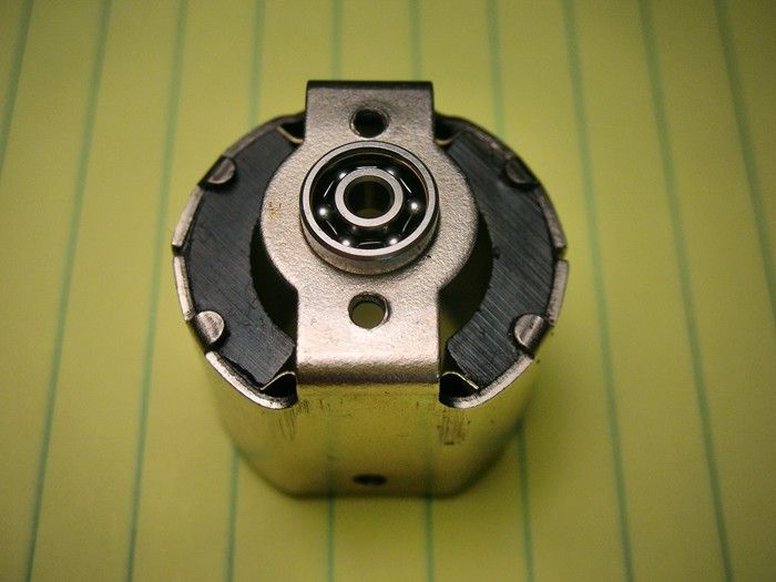
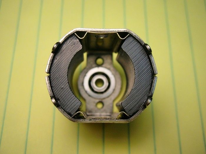
Anyway, here it is going together. Epoxy everywhere! Just like making a mud pie when you were a kid:
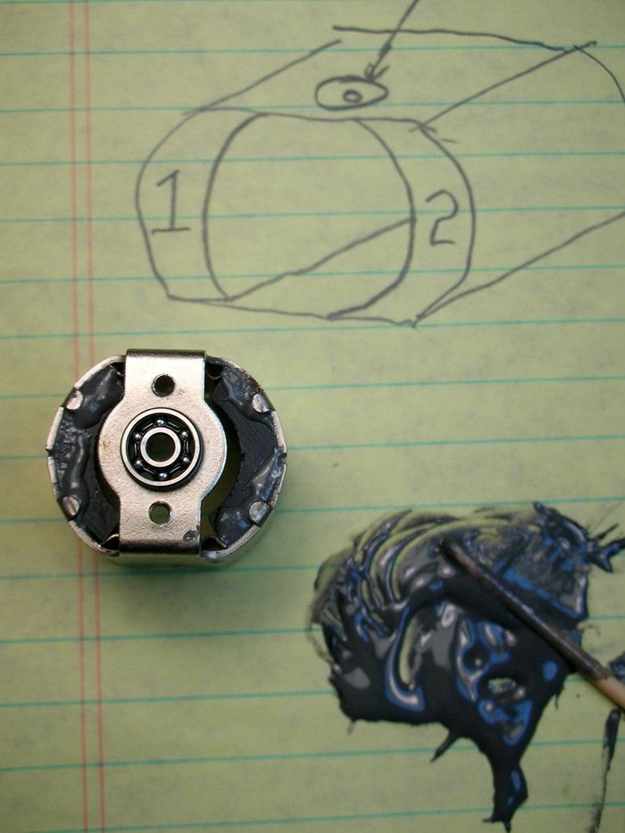
Here it's all cleaned up. I removed the ball bearing shields so I could flush them out. I didn't have a jig motor to build the chassis with. The motor got covered with acid flux and I had to scrub it with soap and water. I think it looks cooler now too:
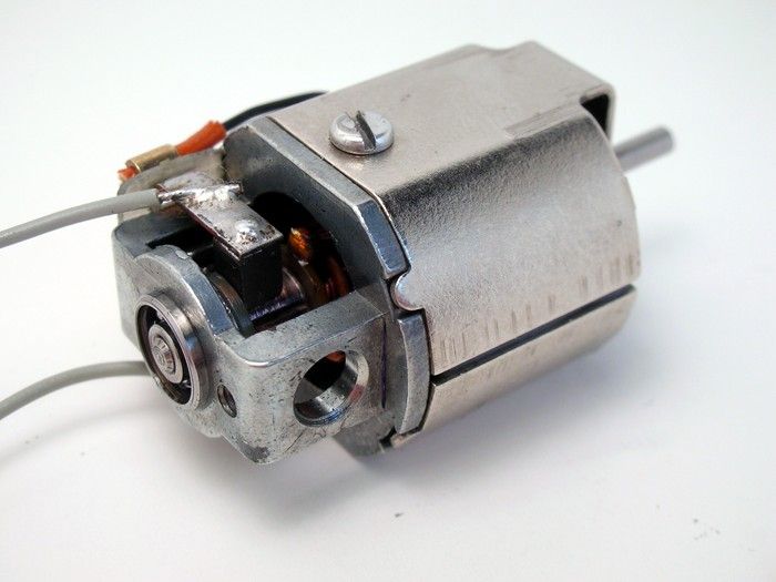
The finished motor:
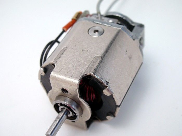
Here's the bottom showing the flat bottom screw that replaced the sheet metal screw that hung down 1/16":
I modified a Simco brush spring to fit to give it a try:
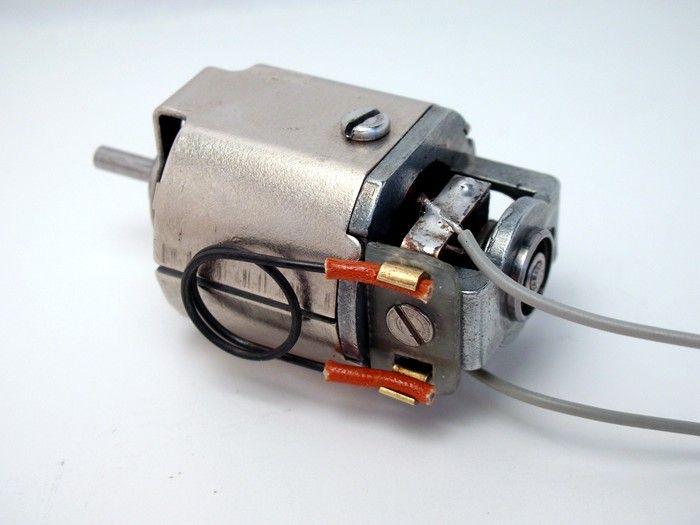
I broke it in at 6V for 20 minutes and it draws about .7 amps.
Time to put the whole thing together
- MarcusPHagen and hiline2 like this
Rick Thigpen
Check out Steve Okeefe's great web site at its new home here at Slotblog:
The Independent Scratchbuilder
There's much more to come...
#75

Posted 14 September 2009 - 05:13 AM
It almost looked as if the shaft was straight but the laminations were running out
-john


