

clap, clap, clap....

The two-rail chassis revolution
Started by
dc-65x
, Dec 11 2010 06:58 PM
143 replies to this topic
#51

tonyp
-

- Member at Peace
-

- 15,325 posts Joined: 12-February 07
Grand Champion Poster
- Gender:Male
- Location:Sanford, FL, land of lizards and big roaches
Posted 06 January 2011 - 09:56 AM
Anthony 'Tonyp' Przybylowicz
5/28/50-12/20/21
Requiescat in Pace
#52
TSR
-

- Full Member
-
- 42,299 posts Joined: 02-February 06
The Dokktor is IN
- Gender:Male
- Location:Marxifornia
Posted 06 January 2011 - 10:19 AM
Rick,
We used to dye the Jet Flags in dark green at Checkpoint and it worked fine...
We used to dye the Jet Flags in dark green at Checkpoint and it worked fine...
Philippe de Lespinay
#53
GTPJoe
-

- Full Member
-
- 448 posts Joined: 26-July 07
On The Lead Lap
- Gender:Male
- Location:Manch-Vegas NH
Posted 06 January 2011 - 06:23 PM
Hi Rick,
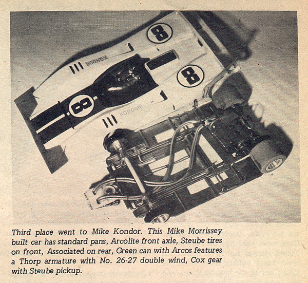
All this Thorp stuff, like the ads, jogged my memory of another chassis shown here awhile back.
And Kondor was at the controller with a Morrissey chassis powered with a Thorp arm..
Remember this?
Maybe another build??
See ya!
All this Thorp stuff, like the ads, jogged my memory of another chassis shown here awhile back.
And Kondor was at the controller with a Morrissey chassis powered with a Thorp arm..
Remember this?
Maybe another build??
See ya!
GTP Joe Connolly
In theory there is no difference between theory and practice.
In practice there is.
#54
dc-65x
-
- Subscriber
-
- 6,976 posts Joined: 14-February 06
Grand Champion Poster
- Gender:Male
- Location:Captain Rick: The only vintage slot car nut in SW Oregon?
Posted 06 January 2011 - 10:22 PM
Hi Joe,
That's a beautiful car Mike built. It's about a year after the 1969 Hinsdale race. Love the C-can at the shallow motor angle.
"So many slot cars to build, so little time".
That's a beautiful car Mike built. It's about a year after the 1969 Hinsdale race. Love the C-can at the shallow motor angle.
"So many slot cars to build, so little time".
Rick Thigpen
Check out Steve Okeefe's great web site at its new home here at Slotblog:
The Independent Scratchbuilder
There's much more to come...
#55
Steve Deiters
-

- Full Member
-
- 2,311 posts Joined: 28-May 07
Posting Leader
- Gender:Male
- Location:Cincinnati, OH
Posted 07 January 2011 - 09:40 AM
Ah yes! A 1/8" Arcolite axle on the front with a segmented axle tube, multi-strand lead wire from the motor, #2 split nose self tapping screw with and oversized washer melted down into the tuncated Jet Flag post,48 pitch Cox spur gear, upright body stiffeners on the rear of the pans,diaplane (probably mylar) and spoiler (probably lexan) stapled to the body, flat brass stock bridging the motor box, notched bat pans,a working drop arm with a straight retention spring of .032 wire, and a chassis with more hinges than rationals to use them driven by a screaming Thorp 26-27 arm in a "C" can....you can almost smell the Dart and lighter fluid in the air!!!Hi Rick,
All this Thorp stuff, like the ads, jogged my memory of another chassis shown here awhile back.
And Kondor was at the controller with a Morrissey chassis powered with a Thorp arm..
Remember this?
Maybe another build??
See ya!
#56
zipper
-

- Full Member
-
- 1,088 posts Joined: 11-August 10
Checkered Flag in Hand
- Gender:Male
- Location:Finland
Posted 07 January 2011 - 11:25 AM
I ditched my Arcolite after the first race as I lost a wheel - didn't realize a flat on the axle might have helped.
Pekka Sippola
#57
tonyp
-
- Member at Peace
-
- 15,325 posts Joined: 12-February 07
Grand Champion Poster
- Gender:Male
- Location:Sanford, FL, land of lizards and big roaches
Posted 07 January 2011 - 12:24 PM
Those fiberglass axles used to grind away the inside of the axle tubes...
Anthony 'Tonyp' Przybylowicz
5/28/50-12/20/21
Requiescat in Pace
#58
Ben Martinez III
-

- Full Member
-
- 4 posts Joined: 08-June 10
Rookie Keyboard Racer
- Gender:Male
- Location:Houston
Posted 07 January 2011 - 04:22 PM
And they were noisy as hell - best lubricant for them was lighter fluid
#59
Jaz
-

- Full Member
-
- 393 posts Joined: 10-March 06
On The Lead Lap
- Gender:Male
- Location:Palm Beach Gardens
Posted 07 January 2011 - 04:40 PM
After being throughly destroyed one nite at Nutley, I bought my first real 'pro' arm from Tango, a Thorp Dbl27. Back on Long Island, I was immediately harassed by Jim Greenaway for my purchase. I used a selection of different arms from various makers like Reeteez and Thorp and a Steube (that one was a rocket!!). My motor building skills of the day were not quite up to snuff and I usually wound up smoking them - the arms that is (it was the 60's).
Finally, I broke down and saved up a princely sum of $40 to have Jim build me a proper motor which lasted quite a long time.
Finally, I broke down and saved up a princely sum of $40 to have Jim build me a proper motor which lasted quite a long time.
Jeff Morris
"If you push something hard enough, it will fall over." Fud's 1st law of opposition
#60
dc-65x
-
- Subscriber
-
- 6,976 posts Joined: 14-February 06
Grand Champion Poster
- Gender:Male
- Location:Captain Rick: The only vintage slot car nut in SW Oregon?
Posted 08 January 2011 - 06:14 PM
You are not going to paint it black?
Black! Black is meaner looking.
Probably an endbell from a Mura M444 that were black...
“So let it be written….so let it be done”. Yul Brynner
Well, I do my best anyway. I’ve never done the black dye thing before…..
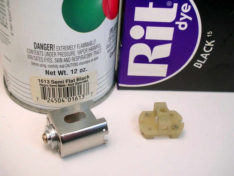
My wife left the house for a while this morning. Time to try dying that endbell
 I broke out the liquid BLACK Rit dye and went to town. I lined the stove and sink with aluminum foil. I also lined the pot but that didn't work, it burned through:
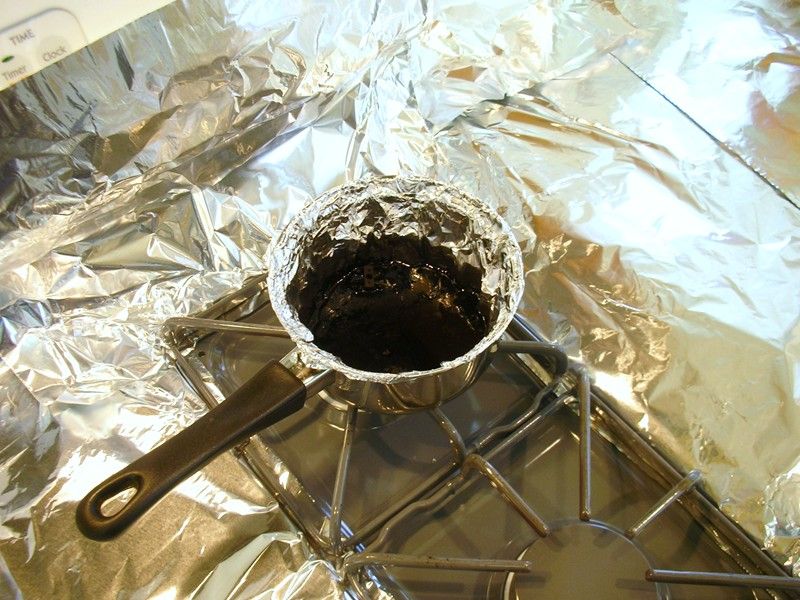
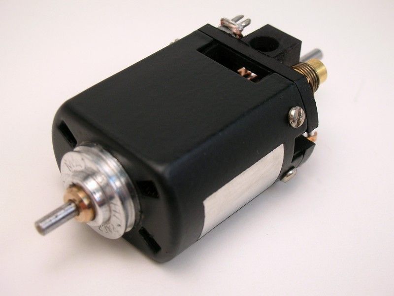
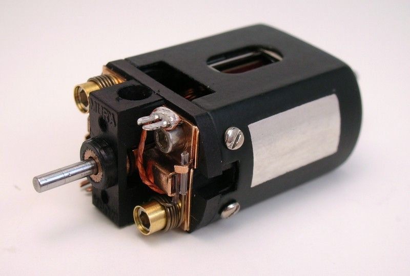
Dying the endbell did work quite nicely. Painting the chrome can worked out too:
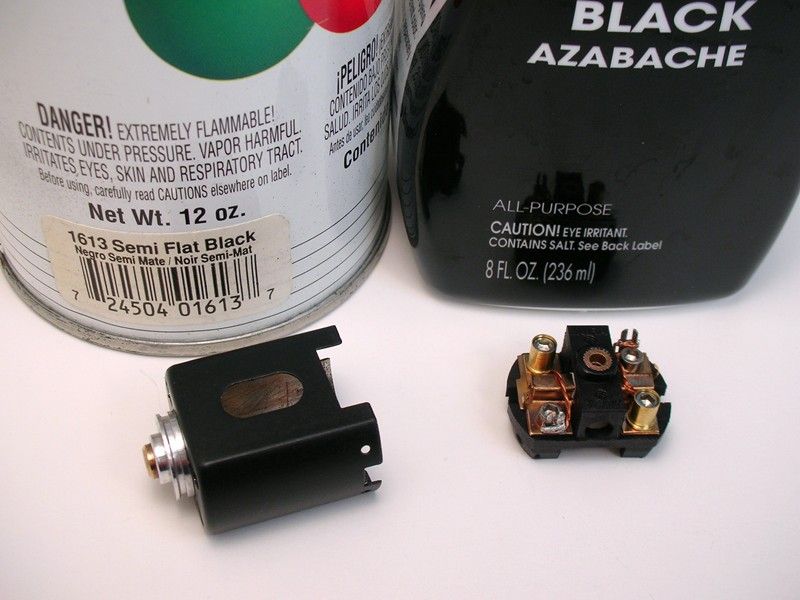
Here's the re-assembled motor in "Evil Bucks Racer" black
 with a masked off and tinned area for soldering the brace:
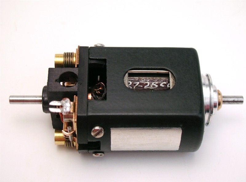
Rick Thigpen
Check out Steve Okeefe's great web site at its new home here at Slotblog:
The Independent Scratchbuilder
There's much more to come...
#61
tonyp
-
- Member at Peace
-
- 15,325 posts Joined: 12-February 07
Grand Champion Poster
- Gender:Male
- Location:Sanford, FL, land of lizards and big roaches
Posted 08 January 2011 - 06:18 PM
Beautiful!
Anthony 'Tonyp' Przybylowicz
5/28/50-12/20/21
Requiescat in Pace
#62
JerseyJohn
-

- Subscriber
-
- 4,198 posts Joined: 05-September 07
Jersey John
- Gender:Male
- Location:Northern NJ
Posted 08 January 2011 - 06:56 PM
Bloomington Gold RICK !!!!!!!!!!!!!!!!!
John Chas Molnar
"Certified Newark Wise Guy since 1984" (retired)
"Certified Tony P Chassis God 2007.2023
Retro Chassis Designer-Builder

#63
dc-65x
-
- Subscriber
-
- 6,976 posts Joined: 14-February 06
Grand Champion Poster
- Gender:Male
- Location:Captain Rick: The only vintage slot car nut in SW Oregon?
Posted 08 January 2011 - 07:17 PM
Thanks Tony and John.
I ran the motor through a break in process again (1.2V - 10 min, 2V - 20 min, 3V - 10 min) and it again ran a bit hot for the first 10 minutes. Then then settled down and ran just a bit warm (not at all hot) for the rest of the process.
I don't know why it ran so hot the first time I ran it. I know the bearings weren't binding then or now.
Maybe it was pissed I didn't paint it black in the first place . Well, whatever, it's sure happy now
  .
.
Another thing I noticed is how smooth it runs. You guys were talking about how good the Thorp balance was and this motor is the smoothest vintage motor I've tried.
Thanks again to everyone for all the input . Time to build a chassis.......
I ran the motor through a break in process again (1.2V - 10 min, 2V - 20 min, 3V - 10 min) and it again ran a bit hot for the first 10 minutes. Then then settled down and ran just a bit warm (not at all hot) for the rest of the process.
I don't know why it ran so hot the first time I ran it. I know the bearings weren't binding then or now.
Maybe it was pissed I didn't paint it black in the first place
. Well, whatever, it's sure happy now .Another thing I noticed is how smooth it runs. You guys were talking about how good the Thorp balance was and this motor is the smoothest vintage motor I've tried.
Thanks again to everyone for all the input
. Time to build a chassis.......
Rick Thigpen
Check out Steve Okeefe's great web site at its new home here at Slotblog:
The Independent Scratchbuilder
There's much more to come...
#64
dc-65x
-
- Subscriber
-
- 6,976 posts Joined: 14-February 06
Grand Champion Poster
- Gender:Male
- Location:Captain Rick: The only vintage slot car nut in SW Oregon?
Posted 09 January 2011 - 10:22 PM
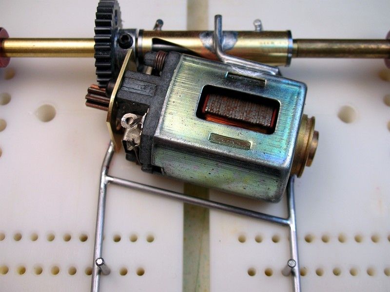
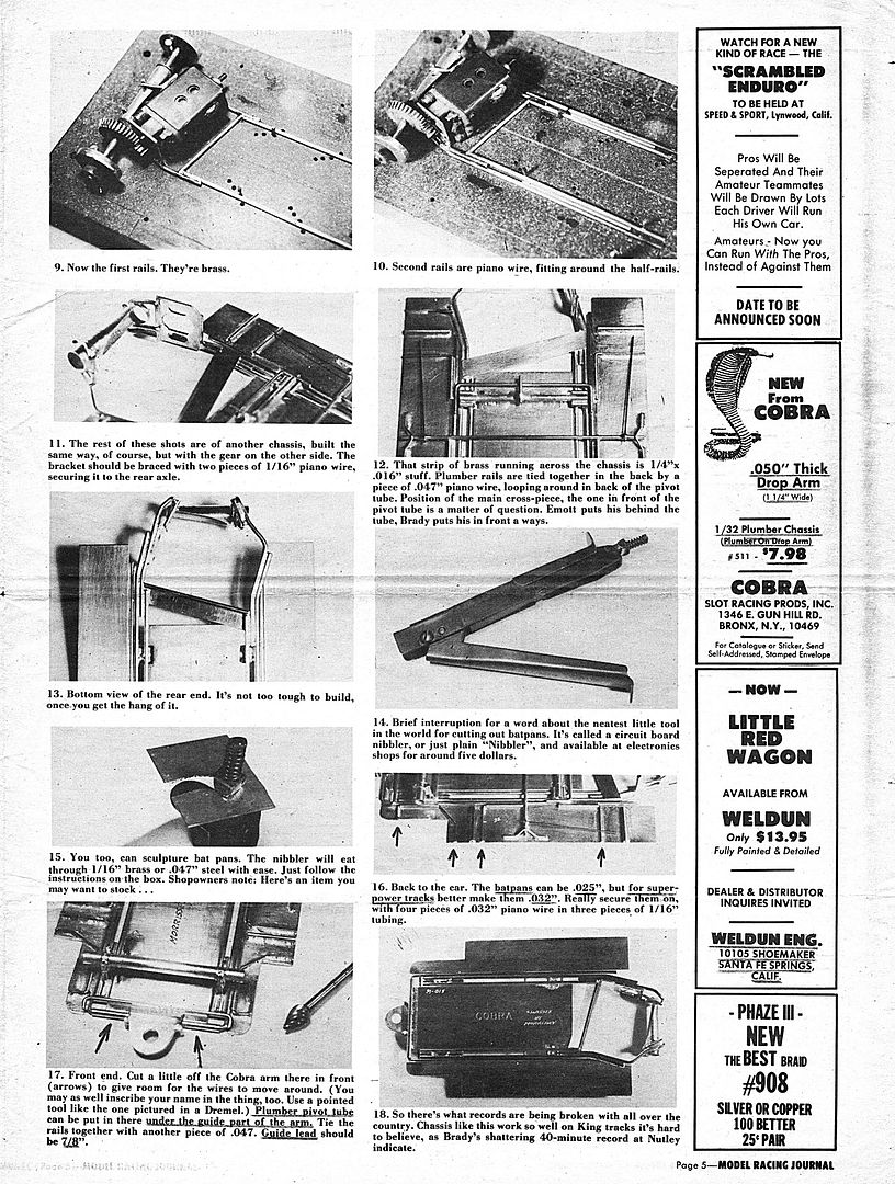
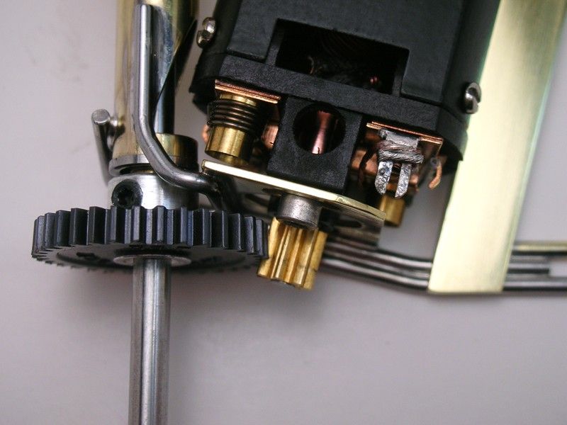
Finally I can start the chassis now that the type of motor I want to use has been decided. So let's follow Mike Morrissey's construction article I posted earlier:
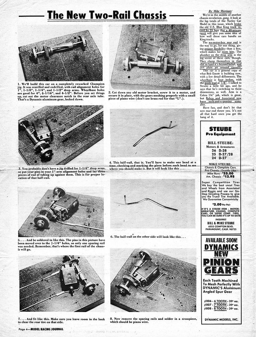
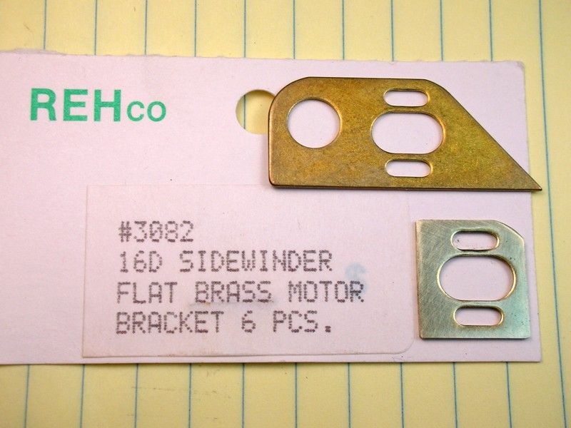
I started with modifying this still available Russkit motor bracket like so:
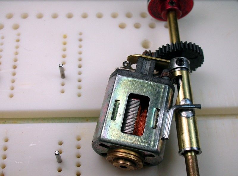
The axle tube is cut to length, relieved and the jig motor soldered in place with an L-brace. I decided on a 15 degree motor angle:
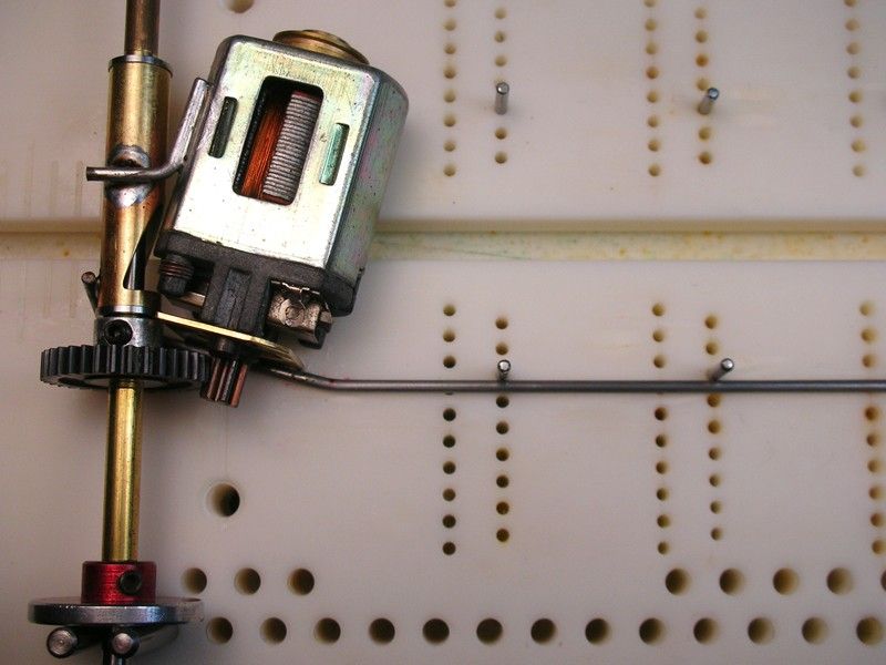
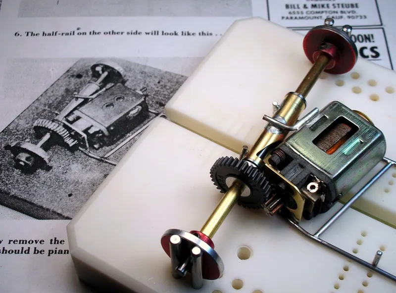
The first "half rail" is installed. Yes I know it supposed to be a half rail and mine are REALLY long. Leaving things long helps me get them REALLY aligned :
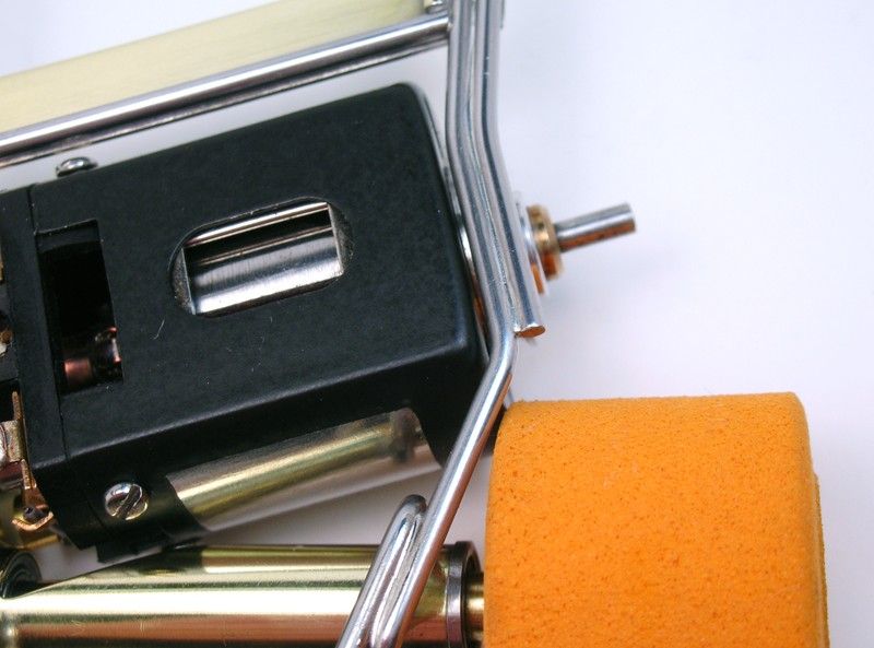
The other half rail has to clear the rear tire. The endbell drive configuration makes this somewhat tricky:
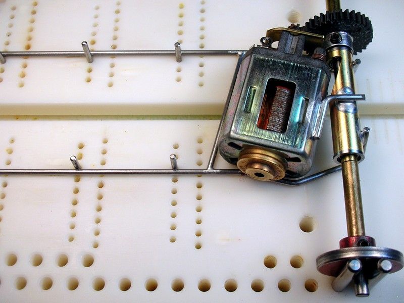
Adding the cross brace ties things together....
....and I'm at step 8 on Mike's construction article:
For me, this was the hard part.
Lets roll
I started with modifying this still available Russkit motor bracket like so:
The axle tube is cut to length, relieved and the jig motor soldered in place with an L-brace. I decided on a 15 degree motor angle:
The first "half rail" is installed. Yes I know it supposed to be a half rail and mine are REALLY long. Leaving things long helps me get them REALLY aligned
:The other half rail has to clear the rear tire. The endbell drive configuration makes this somewhat tricky:
Adding the cross brace ties things together....
....and I'm at step 8 on Mike's construction article:
For me, this was the hard part.
Lets roll
Rick Thigpen
Check out Steve Okeefe's great web site at its new home here at Slotblog:
The Independent Scratchbuilder
There's much more to come...
#65
dc-65x
-
- Subscriber
-
- 6,976 posts Joined: 14-February 06
Grand Champion Poster
- Gender:Male
- Location:Captain Rick: The only vintage slot car nut in SW Oregon?
Posted 16 January 2011 - 04:23 PM
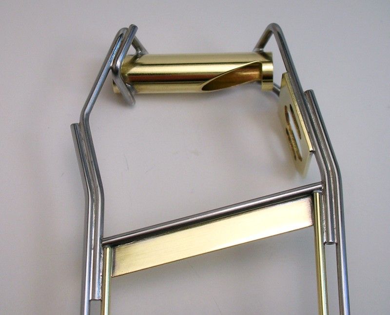
Next up are steps 9 and 10 plus motor bracket and rear axle tube bracing. Mike dropped the ball after step 10 and just showed some finished chassis pictures. I'll try and show the steps he omitted:
Here my Rick's Jig has everything set up for the 1 1/4" drop arm. The half rails are cut to length. The straight inside rails are 1/16" brass, the outers are piano wire bent to match the contour of the half rails:
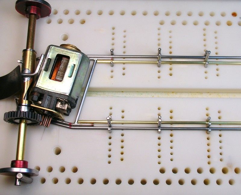
Everything soldered up:
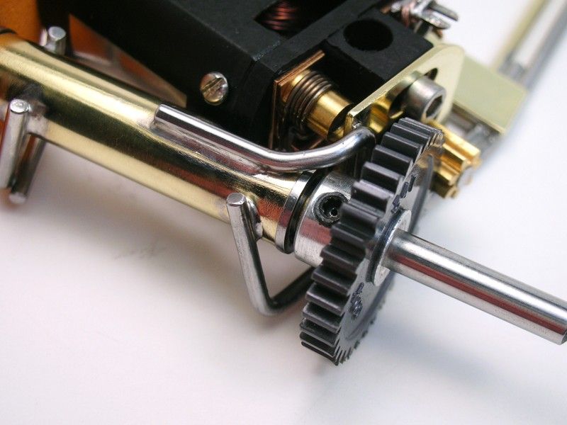
An L-shaped brace strengthens the rear axle tube. Mike faces his rearward like mine. Bob pointed his forward:
Bob attached his motor bracket to axle tube brace on the inside of the bracket. I put mine on the outside like so:
That picture reminded me I need to finish soldering the brace on top of the axle tube. I didn't want to run the solder all the way to the end for fear of soldering in the bearing too.
Anywho, that brace has to clear the spur gear and it takes some fancy-lad bends:
The rear half rail has to clear the motor and rear tire. It's a tight squeeze:
A bottom view:
I add a temporary cross brace on the front until I get the front axle on:
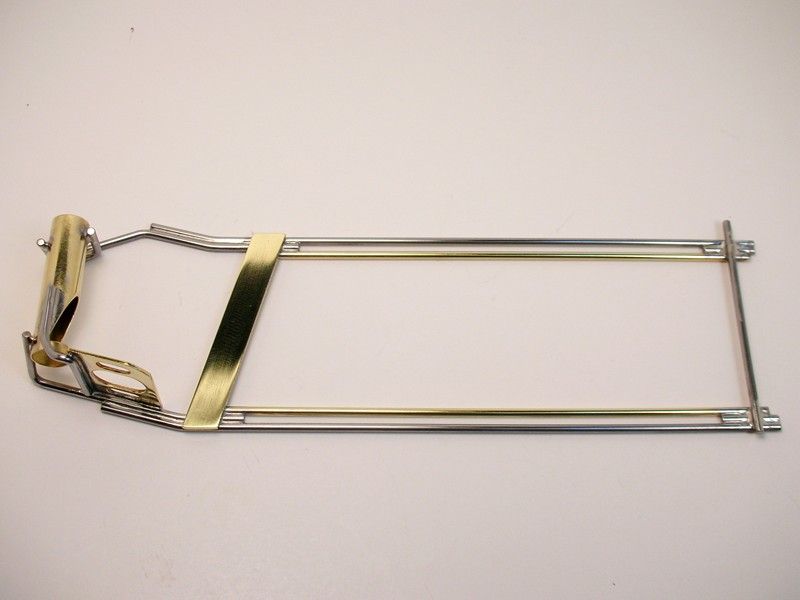
So step 10 is finished and we're on our own......the front axle tube beckons .
Here my Rick's Jig has everything set up for the 1 1/4" drop arm. The half rails are cut to length. The straight inside rails are 1/16" brass, the outers are piano wire bent to match the contour of the half rails:
Everything soldered up:
An L-shaped brace strengthens the rear axle tube. Mike faces his rearward like mine. Bob pointed his forward:
Bob attached his motor bracket to axle tube brace on the inside of the bracket. I put mine on the outside like so:
That picture reminded me I need to finish soldering the brace on top of the axle tube. I didn't want to run the solder all the way to the end for fear of soldering in the bearing too.
Anywho, that brace has to clear the spur gear and it takes some fancy-lad bends:
The rear half rail has to clear the motor and rear tire. It's a tight squeeze:
A bottom view:
I add a temporary cross brace on the front until I get the front axle on:
So step 10 is finished and we're on our own......the front axle tube beckons
.
Rick Thigpen
Check out Steve Okeefe's great web site at its new home here at Slotblog:
The Independent Scratchbuilder
There's much more to come...
#66
Phil Irvin
-

- Full Member
-
- 1,764 posts Joined: 21-July 08
Checkered Flag in Hand
- Gender:Male
- Location:Wesley Chapel, FL
Posted 16 January 2011 - 09:20 PM

Lookin good...Wish I could build so 'nice'..
OLPHRT
PHIL I.

#67
dc-65x
-
- Subscriber
-
- 6,976 posts Joined: 14-February 06
Grand Champion Poster
- Gender:Male
- Location:Captain Rick: The only vintage slot car nut in SW Oregon?
Posted 17 January 2011 - 12:49 AM
Thanks Phil,
I love building these old slot cars. I hope some will build one and stuff some hairy open motor in just like they did back in the day ........PUNCH THE BANK!
I love building these old slot cars. I hope some will build one and stuff some hairy open motor in just like they did back in the day
........PUNCH THE BANK!
Rick Thigpen
Check out Steve Okeefe's great web site at its new home here at Slotblog:
The Independent Scratchbuilder
There's much more to come...
#68
endbelldrive
-

- Member at Peace
-
- 1,740 posts Joined: 16-February 06
Checkered Flag in Hand
- Gender:Male
- Location:Witless Protection Program
Posted 17 January 2011 - 02:25 AM
I love looking at and building these old cars too. I don't have a raceway within a few hundred miles but I build 'em anyway. 
I don't have a raceway within a few hundred miles but I build 'em anyway.
Bob Suzuki
8/19/54-8/?/21
Requiescat in Pace
8/19/54-8/?/21
Requiescat in Pace
#69
Champion 507
-

- Full Member
-
- 1,521 posts Joined: 06-March 09
Checkered Flag in Hand
- Gender:Male
- Location:OK
Posted 17 January 2011 - 04:31 AM
Rick's jig motor looks better than a lot of my running motors

That Champion motor set up with Mura endbell will look mitey fine in that chassis! Good work as always, Rick!
That Champion motor set up with Mura endbell will look mitey fine in that chassis! Good work as always, Rick!
Doug Azary
"We offer prompt service... no matter how long it takes!"
"We're not happy unless you're not happy"
"You want it when?"
"We offer prompt service... no matter how long it takes!"
"We're not happy unless you're not happy"
"You want it when?"
#70
dc-65x
-
- Subscriber
-
- 6,976 posts Joined: 14-February 06
Grand Champion Poster
- Gender:Male
- Location:Captain Rick: The only vintage slot car nut in SW Oregon?
Posted 19 January 2011 - 11:16 PM
I don't have a raceway within a few hundred miles but I'd build 'em anyway.
I hear ya, I would too. Right now I'm lucky to have one within a day trip...THANKS EDDIE!
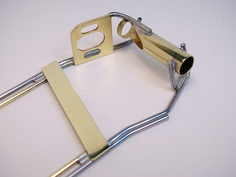
I've got the front axle installed with neato cut-outs in the axle tube:
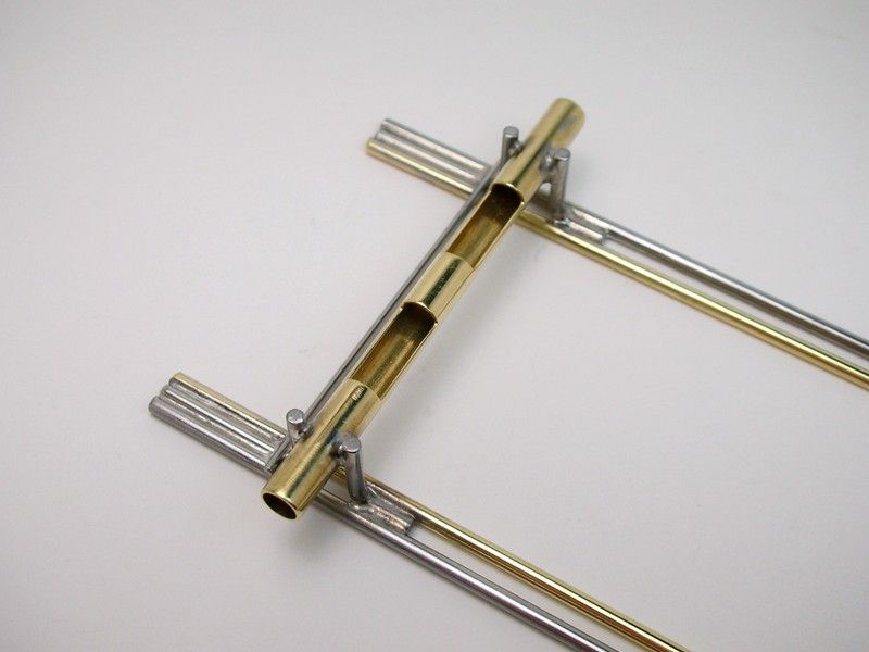
This early car has the rear upright facing toward the rear of the car. Later cars had it facing forward:
The wheelbase is 3 15/16" which was Morrissey considered one of Bob's "short wheelbase" cars in early 1969:
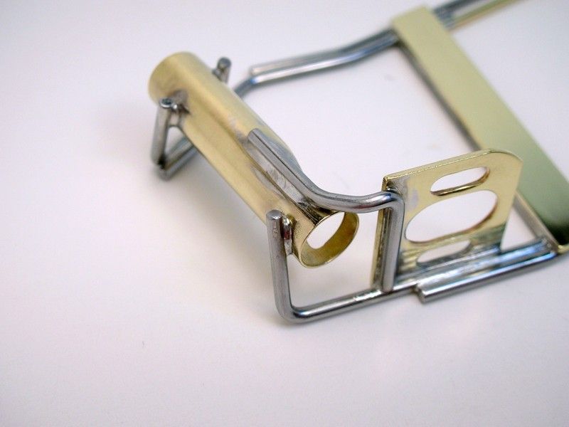
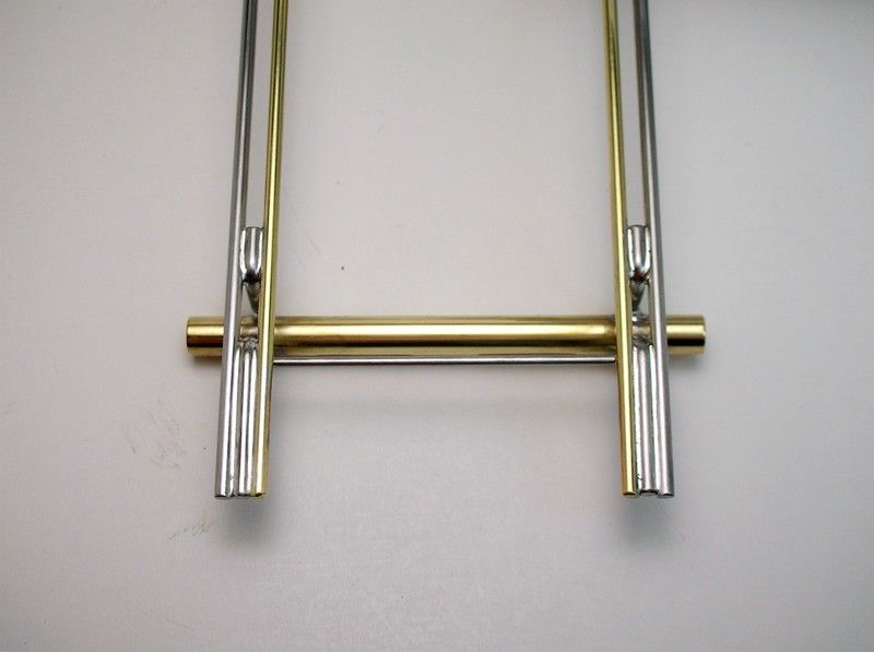
I want to share something that worked really well for me installing the front axle tube:
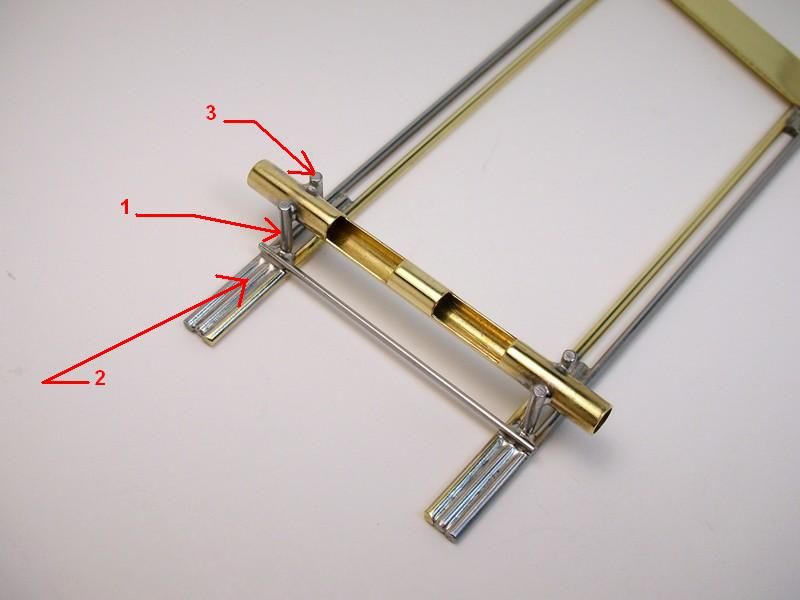
#1: Lay in the front upright. Make it's height a couple of inches longer than needed with a nice 90 degree bend. Put it in place against the front axle tube and get it as aligned as well as you can by eye-ball.
#2: Put a nice little cold solder blob on one side of the upright. This "cold joint" will keep it from falling over but it will still be loose enough to move into alignment. Once you’ve aligned it with a square, solder it to the axle tube.
#3: Now tack the rear upright in place the same way. The extra long ends will make aligning the front and rear uprights easy.
Onward......
Rick Thigpen
Check out Steve Okeefe's great web site at its new home here at Slotblog:
The Independent Scratchbuilder
There's much more to come...
#71
Pablo
-

- Administrator
-
- 18,452 posts Joined: 20-February 06
Builder
- Gender:Male
- Location:Cleveland, Tennessee
Posted 19 January 2011 - 11:28 PM
Paul Wolcott
#72
dc-65x
-
- Subscriber
-
- 6,976 posts Joined: 14-February 06
Grand Champion Poster
- Gender:Male
- Location:Captain Rick: The only vintage slot car nut in SW Oregon?
Posted 30 January 2011 - 02:15 PM
Sometimes all doesn't go smoothly in "Chassis Land". I had some problems that I thought I'd share. Sometimes you just need to fix what went wrong as best you can, learn from it and move on.
I remember when I was working on the shop floor as a machinist. Sometimes as I was making the part I felt like I was "saving" the part from one operation to the next . They would get made to spec but
Anywho, let the adventure begin :
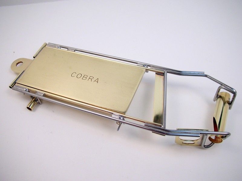
The drop arm is a Cobra 1 1/4" wide by 1/16" brass slab. Bob modified his for the plumber pivot tubes. From the fuzzy pictures I first made mine like this (stock arm on the left):
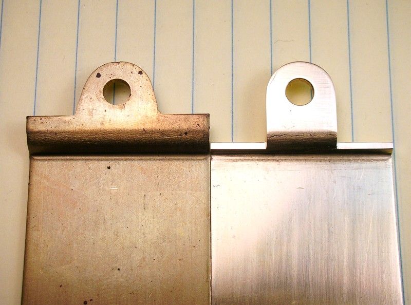
I didn't like that much so I went further:
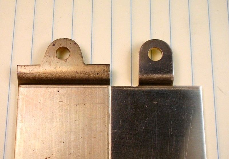
Bob skillfully used a cut-off wheel in a Dremel to relieve the drop arm for "solder stops" for the pivot tube. I substituted my milling machine for skill and cut the reliefs on the right:
Next I had to fix some ugly solder joints . The joint had a solder fillet that was either too small and didn't go evenly across the joint or it was just too big and ugly  .
.
If you are a mere mortal like me stuff like this happens so just fix it . Use the iron to drag the extra solder to a location where it will be easy to remove.......
.....with a Greg Wells "Solder Blob Sucker Upper":
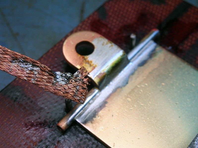
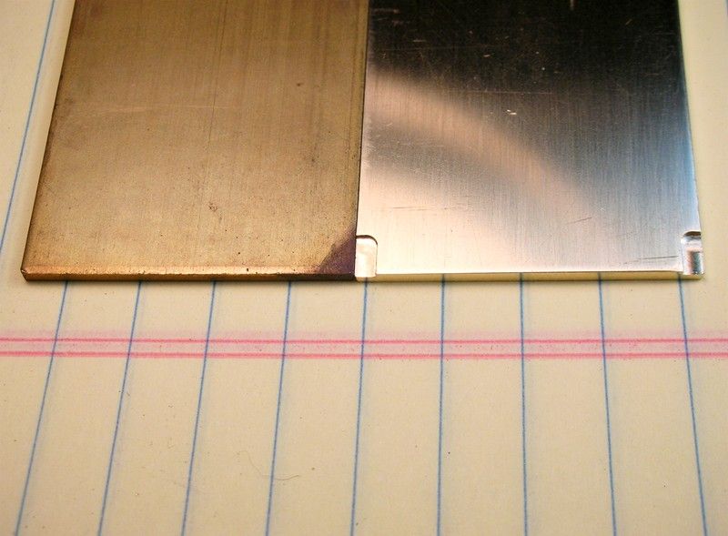
Then the collateral damage where the iron was moved across the drop arm is sanded off and all is well. This NOT shaping the solder joint with files or sandpaper. This is not too bad of a "save":
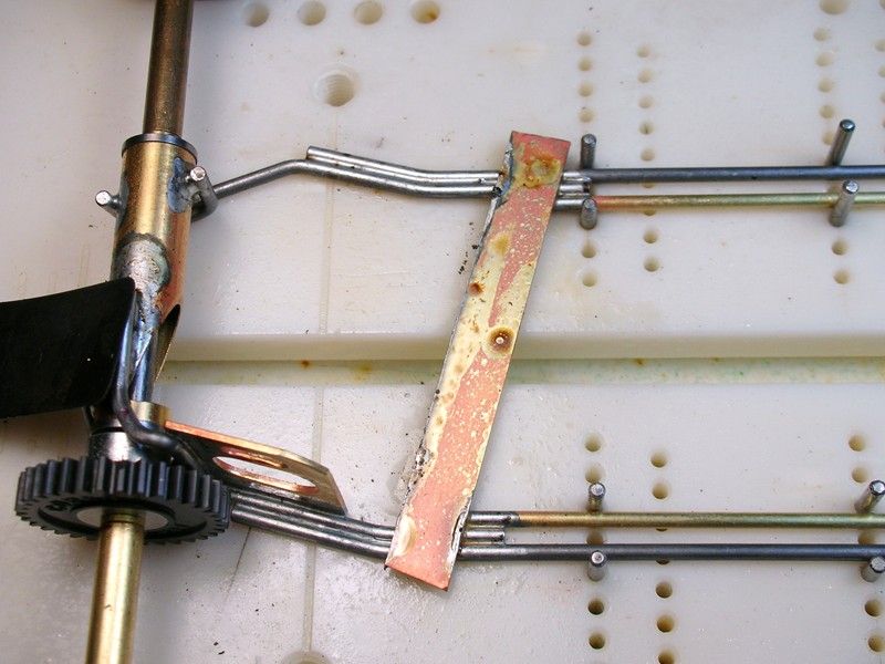
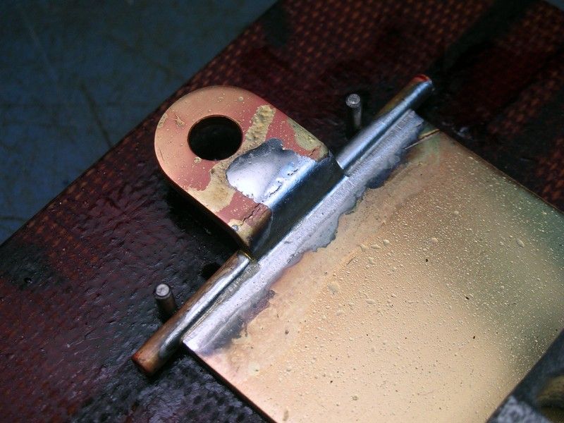
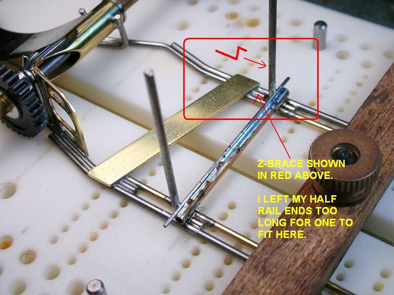
The next problem I really couldn't fix so I had to do a "work around". I figured out how I THINK Bob braced his drop arm pivot tubes after I made my half rails too long. I think he use a Z-brace as shown in red below:
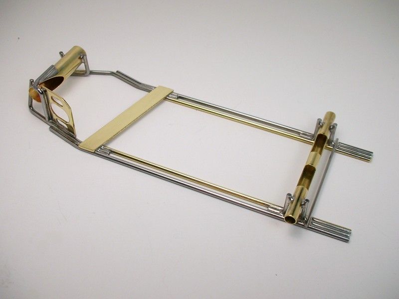
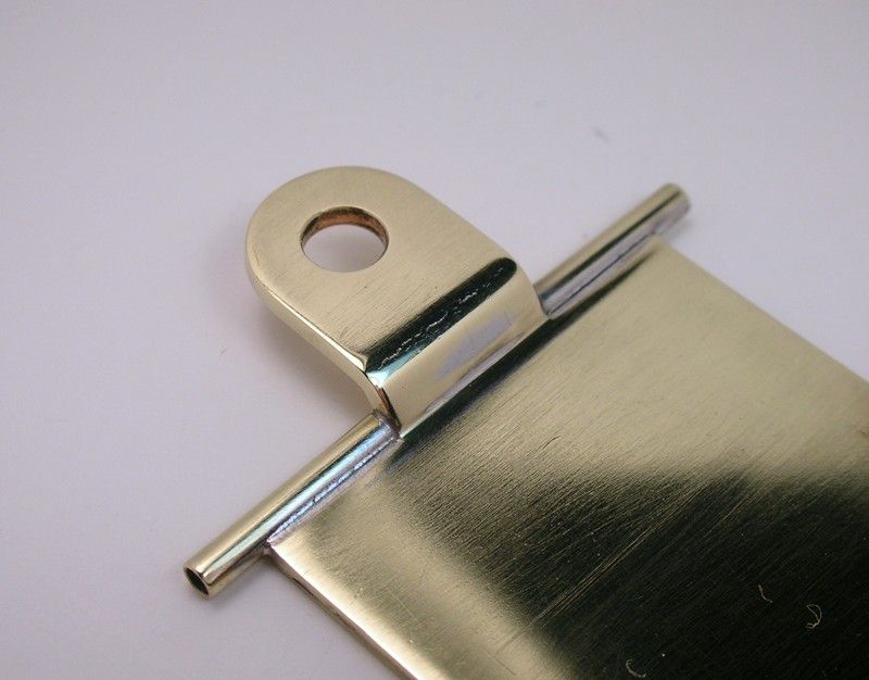
I could have moved my pivot tubes farther forward but I wanted to keep them at the MAGIC 2 1/8" from the front axle that Morrissey spoke of. Instead I used an L-shaped brace going under the pivot tube. Here it is all cleaned up:
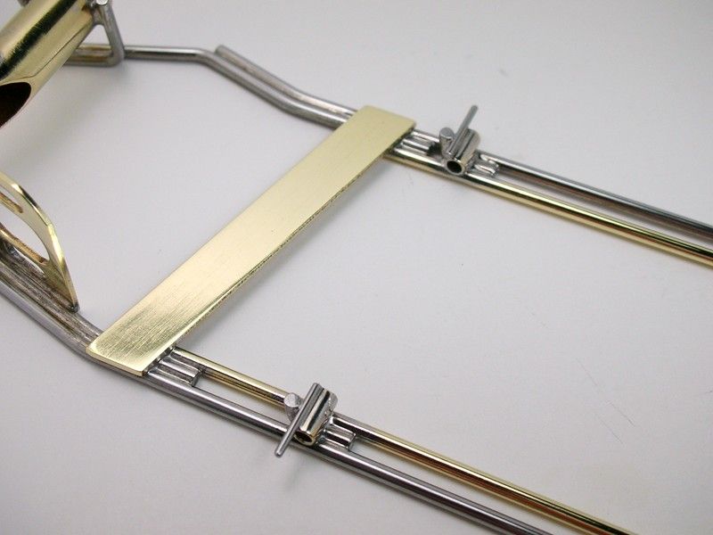
The other dimensions that Morrissey said Howie's chassis had are a 3 15/16" wheelbase and 15/16" guide lead:
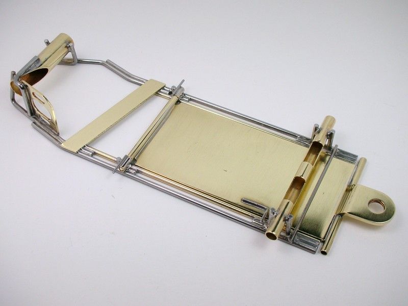
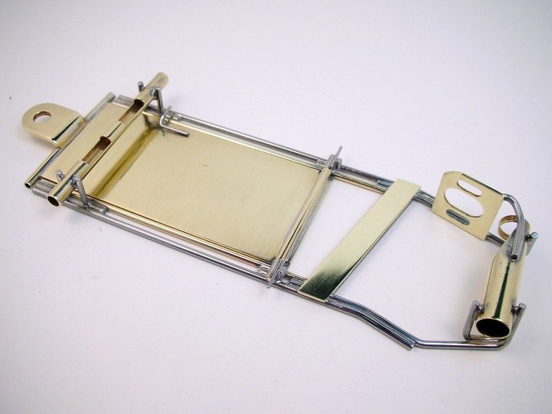
Plumber time.....
I remember when I was working on the shop floor as a machinist. Sometimes as I was making the part I felt like I was "saving" the part from one operation to the next
. They would get made to spec but Anywho, let the adventure begin
:The drop arm is a Cobra 1 1/4" wide by 1/16" brass slab. Bob modified his for the plumber pivot tubes. From the fuzzy pictures I first made mine like this (stock arm on the left):
I didn't like that much so I went further:
Bob skillfully used a cut-off wheel in a Dremel to relieve the drop arm for "solder stops" for the pivot tube. I substituted my milling machine for skill and cut the reliefs on the right:
Next I had to fix some ugly solder joints
. The joint had a solder fillet that was either too small and didn't go evenly across the joint or it was just too big and ugly . If you are a mere mortal like me stuff like this happens so just fix it
. Use the iron to drag the extra solder to a location where it will be easy to remove............with a Greg Wells "Solder Blob Sucker Upper":
Then the collateral damage where the iron was moved across the drop arm is sanded off and all is well. This NOT shaping the solder joint with files or sandpaper. This is not too bad of a "save":
The next problem I really couldn't fix so I had to do a "work around". I figured out how I THINK Bob braced his drop arm pivot tubes after I made my half rails too long. I think he use a Z-brace as shown in red below:
I could have moved my pivot tubes farther forward but I wanted to keep them at the MAGIC 2 1/8" from the front axle that Morrissey spoke of. Instead I used an L-shaped brace going under the pivot tube. Here it is all cleaned up:
The other dimensions that Morrissey said Howie's chassis had are a 3 15/16" wheelbase and 15/16" guide lead:
Plumber time.....
Rick Thigpen
Check out Steve Okeefe's great web site at its new home here at Slotblog:
The Independent Scratchbuilder
There's much more to come...
#73
Duffy
-

- Member at Peace
-
- 3,791 posts Joined: 25-January 09
a dearly-missed departed member
- Gender:Male
- Location:Geographically Brooklyn, Politically Berkeley
Posted 30 January 2011 - 06:04 PM
I'll be happy to see the plumber too. No matter how weird that sounds.
Rikky, I'm goin' sorta crazy here, looking at all that crazing and cracking on a simple z-bend drop arm! We gotta do better than this, and I don't care how long this hasn't been a problem for anyone. Can you send me a drop arm to copy, so I can tool up for a proper job once & for all? I'd like to give it a whack. I think it's a Just Cause.
Duffy
Michael J. Heinrich
1950-2016
Requiescat in Pace
And I am awaiting
perpetually and forever
a renaissance of wonder
1950-2016
Requiescat in Pace
And I am awaiting
perpetually and forever
a renaissance of wonder
#74
dc-65x
-
- Subscriber
-
- 6,976 posts Joined: 14-February 06
Grand Champion Poster
- Gender:Male
- Location:Captain Rick: The only vintage slot car nut in SW Oregon?
Posted 30 January 2011 - 06:50 PM
Hi Duffy,
"That's vintage", my vintage slot car collector mentor Dave used to say. That is the worst Cobra drop arm I've seen so far. They don't grow on trees so they get used crazed or not .
They are much more available than this Team Nutley drop arm:
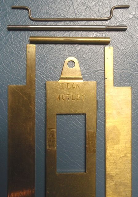
It is similar in shape to the common Parma but much longer and usually made from thicker material. The "TEAM NUTLEY" is also usually stamped a bit neater and lower near the rectangular hole.
They are RARE!. I was desperate enough for one to bid over $100 for this one and I still lost the bid to LASCM (any time I see a feedback of over 4500 on a bidder I assume it's LASCM ). If you really want to make a drop arm, this is the one to make IMHO .
"That's vintage", my vintage slot car collector mentor Dave used to say. That is the worst Cobra drop arm I've seen so far. They don't grow on trees so they get used crazed or not
.They are much more available than this Team Nutley drop arm:
It is similar in shape to the common Parma but much longer and usually made from thicker material. The "TEAM NUTLEY" is also usually stamped a bit neater and lower near the rectangular hole.
They are RARE!. I was desperate enough for one to bid over $100 for this one and I still lost the bid to LASCM (any time I see a feedback of over 4500 on a bidder I assume it's LASCM
). If you really want to make a drop arm, this is the one to make IMHO .
Rick Thigpen
Check out Steve Okeefe's great web site at its new home here at Slotblog:
The Independent Scratchbuilder
There's much more to come...
#75
Duffy
-
- Member at Peace
-
- 3,791 posts Joined: 25-January 09
a dearly-missed departed member
- Gender:Male
- Location:Geographically Brooklyn, Politically Berkeley
Posted 30 January 2011 - 07:03 PM
Well then: done.
Be a good boy, pop over & steal it from LASCM and send it to me, I'll put it through 15-year-old Duffy's CMM and Rhennius Machine, and return it and several perfect clones within the week. --Clones SANS-crazing, certainement.
fra. Dufay
Be a good boy, pop over & steal it from LASCM and send it to me, I'll put it through 15-year-old Duffy's CMM and Rhennius Machine, and return it and several perfect clones within the week. --Clones SANS-crazing, certainement.
fra. Dufay
Michael J. Heinrich
1950-2016
Requiescat in Pace
And I am awaiting
perpetually and forever
a renaissance of wonder
1950-2016
Requiescat in Pace
And I am awaiting
perpetually and forever
a renaissance of wonder


