Hi Martin..........see post #220 about tire diameters ![]()
Replicating Husting's 1966 Top Fuel Eliminator magwinder
#226

Posted 20 May 2020 - 10:39 AM
- hiline2 likes this
Rick Thigpen
Check out Steve Okeefe's great web site at its new home here at Slotblog:
The Independent Scratchbuilder
There's much more to come...
#227

Posted 20 May 2020 - 10:45 AM
Got it. You will need bigger tires, correct?
I probably missed the tight gear mesh solution too?
Thanks Rick.
#228

Posted 20 May 2020 - 10:56 AM
Alan
I understand you are doing a replica of a great car and that dictates the gear guard.
I ask myself why did it need a gear guard in the first place?
In the old days, slot car drag strips often used a pile of silk fabric salvaged from old silk parachutes to slow down and stop the car at the end of its run.
When the car plowed into the silk -- its gears still turning -- the fabric often got caught in the gear mesh and wreaked havoc. Racers had to carefully cut the car apart from the silk that got chewed up by the gears.
So, the gear guard was invented to prevent that from happening. Even so, fabric would sometimes still get caught between the gears and require cutting to extricate the car and clear the track for another run.
Gene Husting's Rod & Custom articles don't say anything about how to fabricate the gear guard. He only says it's made from 0.10" thick magnesium sheet. That's cute. ![]()
There is no way that Husting or Maldonado fabricated their gear guards just using a drill press, a hacksaw and some hand files.
The part is ridiculously hard to make correctly. Husting couldn't possibly detail how to build one in a magazine article.
I am glad the process is over.
I am also glad that I roughed out two of these parts at the same time, so that I don't have to start from scratch again when it comes time to replicate the Manuel Maldonado dragster.
- Eddie Fleming and Phloidboy1 like this
#229

Posted 20 May 2020 - 12:08 PM
Got it. You will need bigger tires, correct?
I probably missed the tight gear mesh solution too?
Thanks Rick.
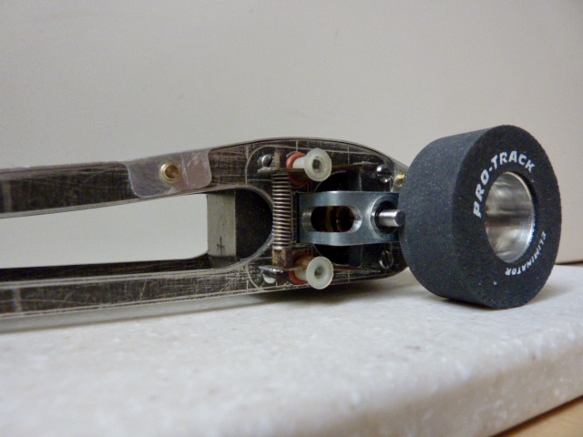
Tires larger than 1-5/16" diameter? Yes and no.
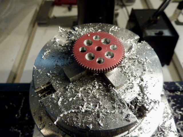
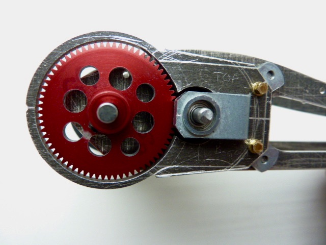
Gene Husting's Rod & Custom magazine article photos show that he filed a small flat spot on the bottom of his gear guard's spur gear ring.
There isn't much material left on the spur gear "ring" once the part is milled to spec, so the smallest flat spot possible is created to provide a slight amount of clearance, which is fine for drag racing.
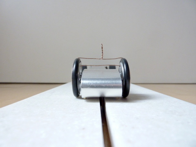
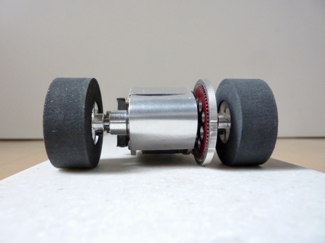
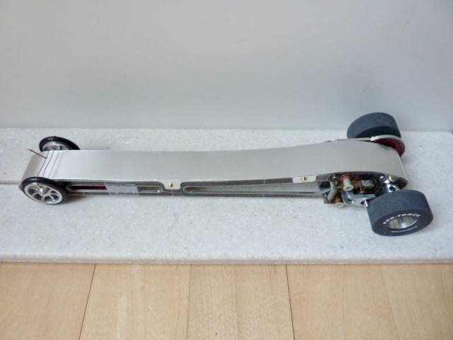
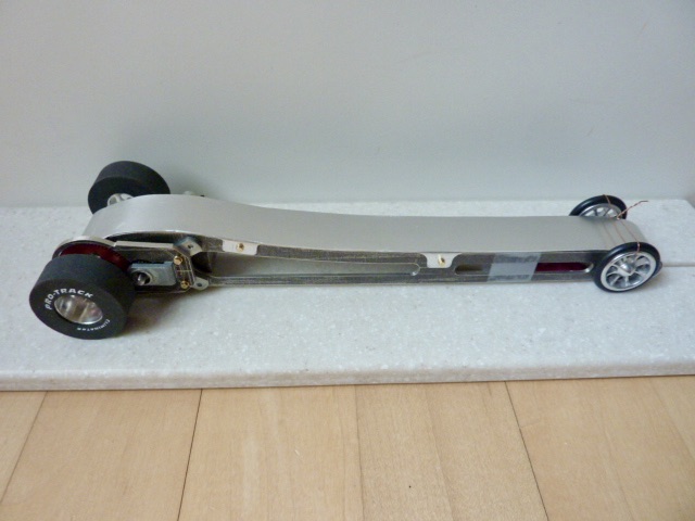
Based on how my replica of Gene's car sits, the gear guard barely clears the track surface with 1-5/16" diameter tires, but it does clear. You have to press down slightly to make contact between the bottom of the gear guard and the track surface.
The Pro-Track "Eliminator" wheels and tires are obviously store-bought, but they serve the same purpose for me as "jig wheels" for these dragster projects.
One of the last steps in building this car will be mounting donuts -- Graupner Record Elastik and other new rubber -- onto Russkit dragster wheels and grinding them to size. Anything over 1-5/16" and under 1-3/8" diameter will work at the track.
I also have this goofy theory that the rear tire's diameter expands slightly at speed through centrifugal forces just like full size dragsters' do. That might help lift the rear end up a sliver. ![]()
On the other hand, maybe the rear end squats down at the start and the gear guard bottoms out? ![]()
Hard to say at this point, but that's how the Pro's did things things back in 1966. ![]()
Overall, I still think Husting's magwinder design is brilliant. It's deceptively simple, but like most of the magwinder's pictured in Howie Ursaner's thread, "Magwinders and 60's drag racing", it's very sophisticated. ![]()
- hiline2 and Phloidboy1 like this
#230

Posted 20 May 2020 - 12:32 PM
Man, that is close to the track. I guess there was no minimum track clearance rule then. You may leave your mark at Mikes new track?
Following your epic build. Remember you saying the gear mesh was too tight. Did you mention the fix for that?
I am always nervous about fixed gearing, but I get they did it that way.
The gear mesh is what it is based on the rear axle and pinion shaft center-to-center dimension of 0.7188" as dictated by "Machinery's Handbook" of facts/ formulae necessary for manufacturing gears.
Gear mesh feels just right, although it helps to know that you followed the Handbook's rules exactly, so it must be "right". ![]()
With machinery and machining processes, there is no fudge factor. The fixed gear formulae are no different.
- hiline2 likes this
#231

Posted 20 May 2020 - 12:37 PM
Hi Martin,
I did mention an issue with the armature. When it was first installed, there was no room or play for the armature between the endplate bearings.
Posts #186 and #187 show how that issue was resolved. ![]()
- hiline2 and Phloidboy1 like this
#232

Posted 20 May 2020 - 03:30 PM
I must be losing it, ![]() or it was MY worst night mare. Doing all that work to have the gear mesh too tight. That was my fear. But thanks for the clarification.
or it was MY worst night mare. Doing all that work to have the gear mesh too tight. That was my fear. But thanks for the clarification.
Glad it all worked as planed. I now want one. Thanks to you ![]()
#233

Posted 20 May 2020 - 09:17 PM
Hi Martin,
You're not losing it. ![]()
I was even more confused about gear-making in general, the laws of fixed gear set-up's, and the simple mechanics of changing gear ratios in fixed gear set-up's in particular, until Rick T./ DC-65x clarified things somewhere earlier in this or a related thread.
The thing about the gear mesh on my Husting replica is that it's not tight or binding, but it doesn't have any play or backlash in it either, like you might dial into an angle winder's or even an in-line's crown and pinion gear meshes.
But it's perfectly "correct" per the Machinery formula and that's good enough for me. ![]()
- hiline2 likes this
#236

Posted 28 May 2020 - 12:39 PM
With the body out of the way, I can turn my attention back to the motor and finishing details.
Before I do that, however, I need to deal with the driver figure and roll bar, both required by 1966 class rules.
- hiline2 and Howie Ursaner like this
#237

Posted 28 May 2020 - 02:20 PM
The devil is in the details...
I know how I want to mount the driver figure/ roll bar, but I haven't figured out how or where to attach the fixed end of a piano wire spring for the drop arm.
According to Husting, the pick up drop arm "... should also be very lightly loaded to make sure the stranded copper pick up makes good contact all the way down the strip."
The Husting Rod & Custom build photos just show the spring wire attached to the drop arm and then disappearing somewhere off towards the motor.
The fixed end of the wire spring on Husting's car is attached to a point on the chassis located behind the driver figure, exactly where or how I can't tell.
- hiline2 likes this
#238

Posted 28 May 2020 - 02:31 PM
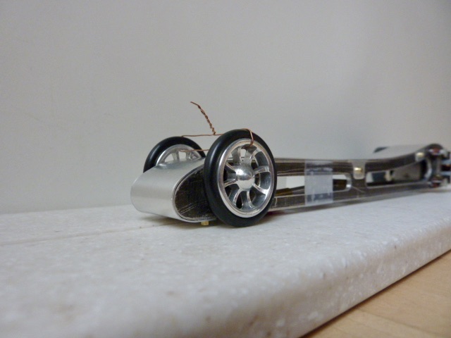
Another detail which explains why the front wheels are temporarily wired together is that the stock wheels and bearings are supposed to be a very firm press fit onto the 1/8" steel axle. Once the front wheel is "on" the axle, it's not supposed to be easily pulled off.
In my case both of these used vintage front wheels and bearings are an easy slip fit onto the current front axle, so that's an issue I need to address.
- hiline2 likes this
#239

Posted 28 May 2020 - 02:49 PM
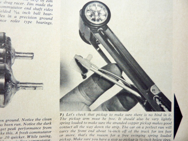
For this one photo caption Gene Husting writes, "The car on a perfect run will carry the front end 1/4-inch off the track for ten feet or more, that's the reason for a free-swinging spring loaded pickup."
"Make sure you have a stop so pickup is 1/4-inch below tires".
This is the photo...
- hiline2 likes this
#240

Posted 28 May 2020 - 02:59 PM
"Make sure you have a stop so pickup is 1/4-inch below tires."
I know what a "stop" is and what stopping a pickup arm from dropping below 1/4-inch below the front wheels means, but that photo doesn't look like there is a stop because the pickup is well below 1/4-inch of the front wheels the way Husting's forefinger is holding it.
Does the wire spring act both to lightly load the pickup and prevent the drop arm from swinging down in an uncontrolled way? ![]()
If anyone knows, please chime in. ![]()
- hiline2 likes this
#241

Posted 28 May 2020 - 03:03 PM
Is he saying that in the up position the arm should stop with 1/4 in of guide below the tires?
Just a thought I have no idea.
#242

Posted 28 May 2020 - 03:17 PM
Alan,
I've always seen those types of front wheels described as needing loctite or something similar to hold the bearing in the wheel and the axle to the inner race of the bearing... never seen one described as a push fit, and that seems prone to losing a wheel at some point!
For the 1/4" no idea either... maybe he just let it drop more to illustrate the drop arm, and he either put in a stop later, or the wire spring acts as the stop as you say... nothing in any of the other construction articles either? I'll see if I can find something...
Don
- hiline2 likes this
#243

Posted 28 May 2020 - 04:05 PM
Hi Eddie and Don,
As I thought about it more I decided that "1/4-inch" was a typo or the magazine editor's flub and that it should have read "3/4-inch", in which case that photo sort of works. ![]()
- hiline2 likes this
#244

Posted 28 May 2020 - 04:13 PM
Hi Martin and Don,
Yeah, I figured I was going to have to Loctite the front wheels onto the axle. I guess green is the way to go, although it's not easy to break the bond without heat as I've read, since I haven't tried this myself yet.
As you say, Martin, that final step of attaching the wheels to the axle takes place when I'm "ready to commit", and I've got a ways to go before that can happen.
- hiline2 likes this
#245

Posted 28 May 2020 - 04:13 PM
Good thinking Alan!
Just looked through most of the dragster articles I could find, and the only one showing an attachment point for the spring is in the April 64 Car Model article on Bob Lindsay. It's screwed to the inside of the frame about an inch ahead of the drop arm pivot and in the upper third of the rail... but that's on his test dragster to check out his different armatures. Didn't see any indication like that on any of Hustings' machines.
Don
#246

Posted 28 May 2020 - 04:23 PM
Hi Don,
Gene Husting's series of Rod & Custom construction articles have other typo's involving numbers that the reader has to puzzle out.
One of them involved the caption under a photo showing how to build the drop arm. It said make a "T" using "9/32-inch" brass tubing, when it should have read "5/32-inch" tubing.
- hiline2 likes this
#247

Posted 28 May 2020 - 04:30 PM
Hi Martin and Don,
Yeah, I figured I was going to have to Loctite the front wheels onto the axle. I guess green is the way to go, although it's not easy to break the bond without heat as I've read, since I haven't done this myself.
As you say, Martin, that step takes place when I'm "ready to commit" and I've got a ways to go before I can do that.
Is Green the weakest Loctite, or is it Blue?
I definitely wouldn't use Red.
Any chance slightly tinning the axle with solder, would work?
I also have some plated 1/8" piano wire.
The plating is very thin, but it does measures slightly bigger than a Koford 1/8".
Mike Swiss
Inventor of the Low CG guide flag 4/20/18
IRRA® Components Committee Chairman
Five-time USRA National Champion (two G7, one G27, two G7 Senior)
Two-time G7 World Champion (1988, 1990), eight G7 main appearances
Eight-time G7 King track single lap world record holder
17B West Ogden Ave., Westmont, IL 60559, (708) 203-8003, mikeswiss86@hotmail.com (also my PayPal address)
Note: Send all USPS packages and mail to: 692 Citadel Drive, Westmont, Illinois 60559
#248

Posted 28 May 2020 - 04:33 PM
Good thinking Alan!
Just looked through most of the dragster articles I could find, and the only one showing an attachment point for the spring is in the April 64 Car Model article on Bob Lindsay. It's screwed to the inside of the frame about an inch ahead of the drop arm pivot and in the upper third of the rail... but that's on his test dragster to check out his different armatures. Didn't see any indication like that on any of Hustings' machines.
Don
I'm thinking that the wire spring's attachment point will be a small magnesium block epoxied to the inside face of the left or right frame rail's upper or lower horizontal stile. The block will have small wire-sized hole drilled through it and the fixed end of the drop arm's spring will be glued into the block. The wire will need to coil around the drop arm's pivot 2 - 3 times I suppose. It's something I'll experiment with.
I don't want to drill any more holes in the mag rails.
One of the reason's I'm holding off installing a driver figure (located just behind the drop arm's pivot point midway in the chassis, per Husting's build photos), is to coordinate that installation with the drop arm spring mechanism. I don't want the driver to interfere with the spring's fixed mount or with its operation.
- hiline2 likes this
#249

Posted 28 May 2020 - 04:41 PM
Hi Mike,
Blue is the "removable" Loctite. Green "Penetrates assembled parts". Red is "permanent".
With green Loctite you have to be careful it doesn't wick into the wrong places, like ball bearings and wheel spacers. ![]()
Given the fact that the axle ends are covered by "hubcaps" and are inaccessible, I'm giving serious consideration to tinning the axle ends with solder and press-fitting the wheels per their original design and avoiding the messy Loctite approach.
Disassembly is still going to be a trial.
- hiline2 likes this
#250

Posted 28 May 2020 - 09:43 PM
In Part Three of Gene Husting's Rod & Custom magazine articles about this car, in which he reveals some of his "speed secrets", Husting says...
"If the car you are tuning is powered by a Ram 850 or a Ram 857, make sure the motor is installed in the car with the brushes on the left hand side of the car.
This is very important. The armatures are wound so that in one direction of rotation the commutators are advanced and in the other direction, retarded."
I did not know that. I suppose that since the equivalent Pittman 85A armature commutators are "neutral" -- equal speeds in either direction -- it follows that Ram armatures were designed to run at higher rpm's than Pittman armatures. Also, Ram armatures have seven poles compared with Pittman's five pole armatures. I don't know what seven poles does for an armature's performance, but it sure looks cool. ![]()
Did Ram motors dominate in the dragster class in the mid-1960's?
- hiline2 likes this


