


usually the outer front corners of the chassis are used to contact the track, in lieu of the front wheels.

Lancer scale McLaren M6 Can-Am build
Started by
dc-65x
, Jan 22 2026 05:50 PM
106 replies to this topic
#26

SpeedyNH
-

- Full Member
-

- 820 posts Joined: 18-July 15
Old Engineer
- Gender:Male
- Location:Cow Hampshire
Posted 15 February 2026 - 08:04 AM
- John Luongo likes this
Steve Lang
#27
Brian Czeiner
-

- Full Member
-
- 601 posts Joined: 04-March 08
Race Leader
- Gender:Male
- Location:Tyler, TX
Posted 15 February 2026 - 03:16 PM
1/24 Pro type cars evolved during the time period I'm interested in (early 60's to early 70's) from solid front axles to ISO fronts to independent L-arm front axles.
I really enjoy the building part of the hobby and I'm less of a slot car handling theory expert. Hopefully someone here can tell us why these cars relied less and less on their front wheels.
Without being harsh, in our quest for speed we allowed it to the point where slotcars have stickers for front wheels. Its the same reason the hobby stepped away from the scale appearance with larger than life rear spoilers and altered body lines. I am glad to see builders and painters like DC and others push the scale/building aspects of the hobby.
- munter, olescratch, Eddie Fleming and 1 other like this
If it's not a Caveman, It's HISTORY! Support Your local raceways!
#28
dc-65x
-
- Subscriber
-
- 7,204 posts Joined: 14-February 06
Grand Champion Poster
- Gender:Male
- Location:Captain Rick: The only vintage slot car nut in SW Oregon?
Posted 15 February 2026 - 09:21 PM
Thanks Steve 
Brian, I'm really enjoying working with these absolutely gorgeous 1968 Lancer scale CanAm bodies. Shrinking down Pro car type chassis to fit them has been fun.
Speaking of fun, I've started soldering things together:
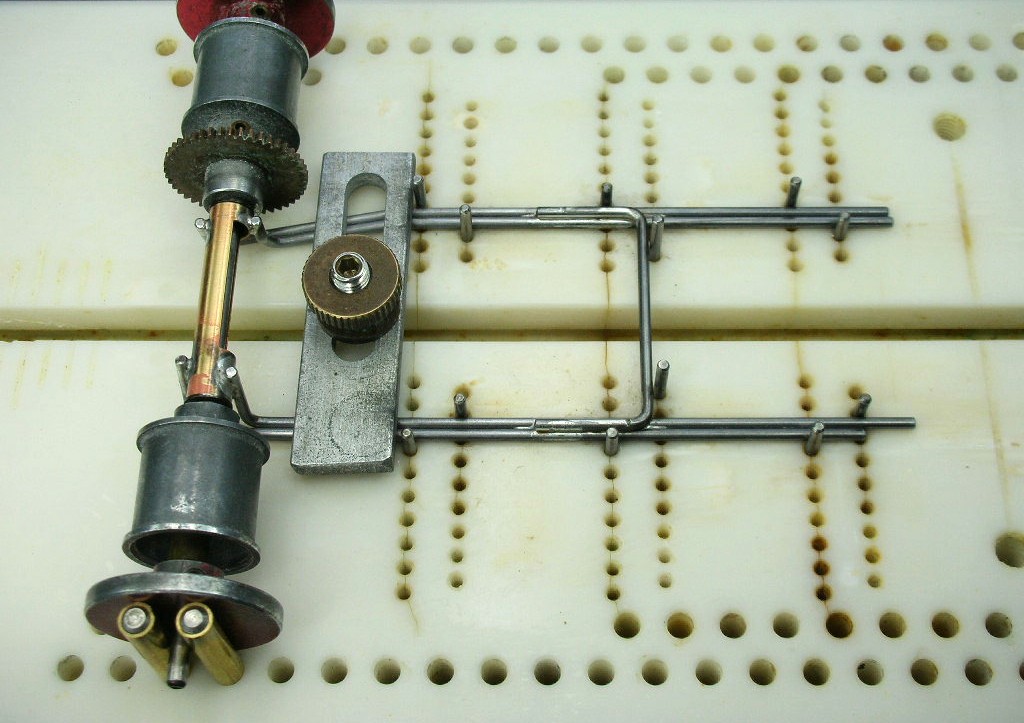
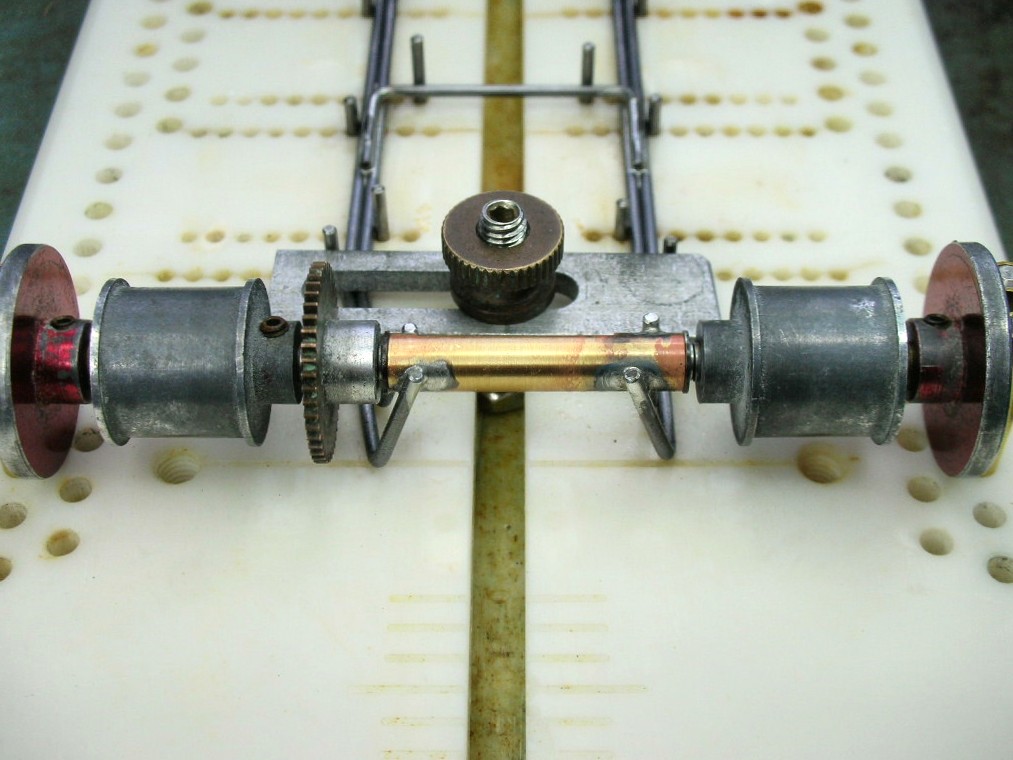
The extra long half rails trimmed to length and a good scrubbing with a grey Scotch Brite pad:
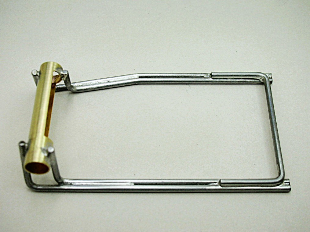
So far, so good. Rear axle tube, half rails and plumber hinge mount:
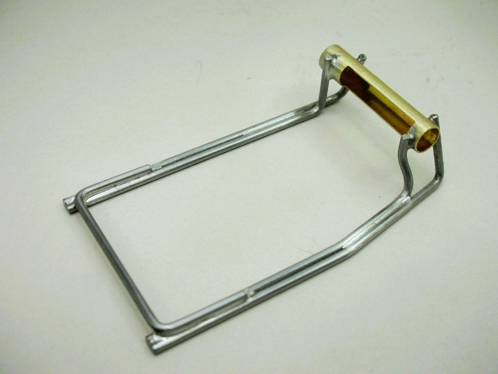
Next is notching the half rails for the lower motor mount screw, motor mount and its brace.
- Pablo, Tex, Brian Czeiner and 1 other like this
Rick Thigpen
Check out Steve Okeefe's great web site at its new home here at Slotblog:
The Independent Scratchbuilder
There's much more to come...
#29
dc-65x
-
- Subscriber
-
- 7,204 posts Joined: 14-February 06
Grand Champion Poster
- Gender:Male
- Location:Captain Rick: The only vintage slot car nut in SW Oregon?
Posted 16 February 2026 - 09:56 PM
The motor bracket installed:
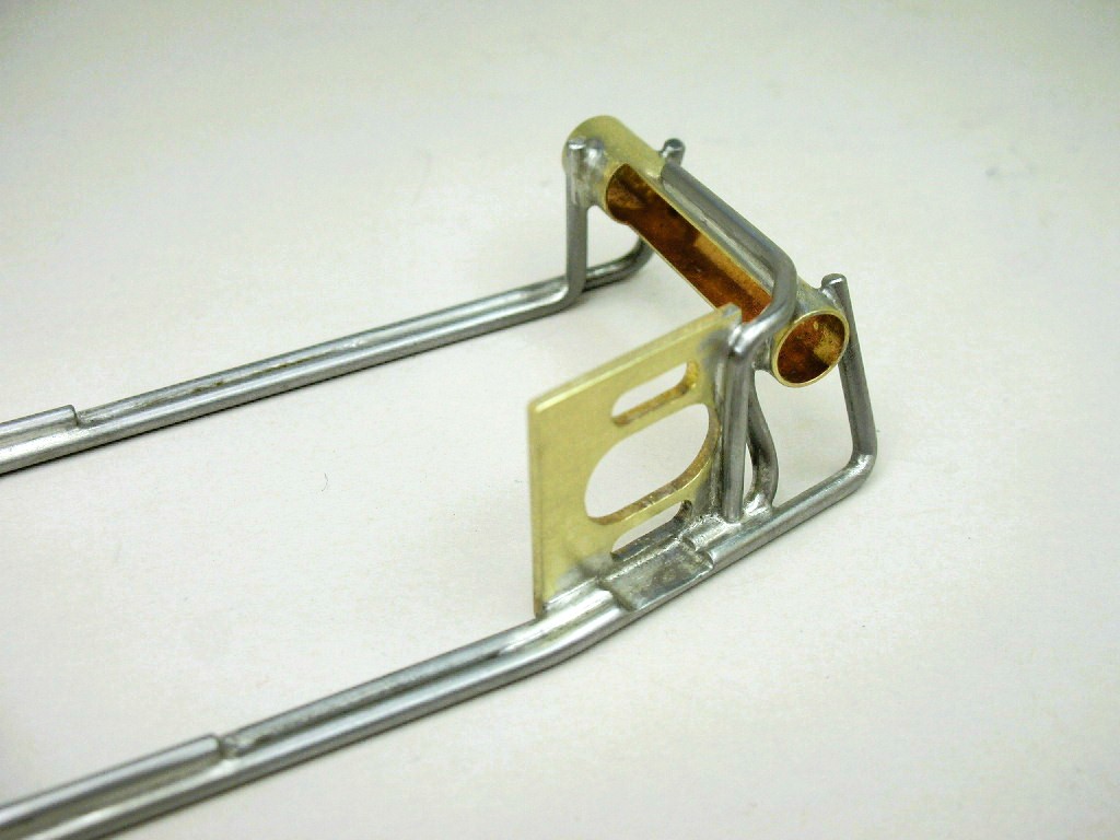
The half rails are notched for the lower motor mount screw:
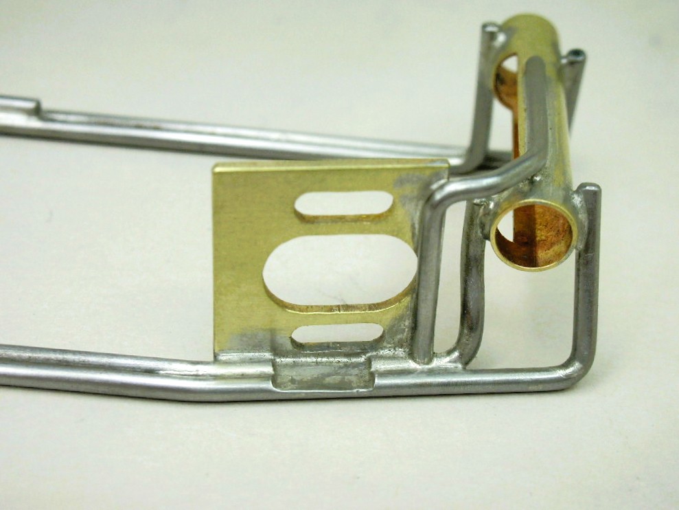
Now the axle tube and motor mount are tied together:
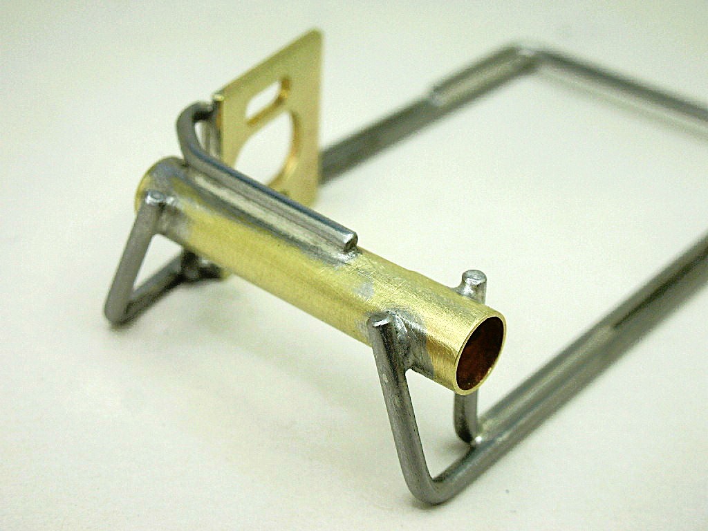
Time to attach a center section.
- Tex, Jaeger Team and Larry Horner like this
Rick Thigpen
Check out Steve Okeefe's great web site at its new home here at Slotblog:
The Independent Scratchbuilder
There's much more to come...
#30
Mbloes
-

- Subscriber
-
- 633 posts Joined: 19-April 12
Race Leader
- Gender:Male
- Location:Los Angeles, CA
Posted 16 February 2026 - 10:12 PM
1/24 Pro type cars evolved during the time period I'm interested in (early 60's to early 70's) from solid front axles to ISO fronts to independent L-arm front axles.
I really enjoy the building part of the hobby and I'm less of a slot car handling theory expert. Hopefully someone here can tell us why these cars relied less and less on their front wheels.
I honestly believe the turning point (which was truly an "aha" moment) was when the pivot was placed on the center rail, like "modern" eurosport cars. That way, the rear tire assembly could pivot and "bite" independent of the chassis at large. You could even have a solid front axle, like early eurosports cars, and the rear would still pivot and bite.
All of the sprung drop arms or front wheel assemblies were an attempt to get there, but never did. Even the L shaped front axles didn't solve the problem; the center "rectangle" still remained solid.
Mike Bloes
#31
Mbloes
-
- Subscriber
-
- 633 posts Joined: 19-April 12
Race Leader
- Gender:Male
- Location:Los Angeles, CA
Posted 16 February 2026 - 10:29 PM
Mike Bloes
#32
dc-65x
-
- Subscriber
-
- 7,204 posts Joined: 14-February 06
Grand Champion Poster
- Gender:Male
- Location:Captain Rick: The only vintage slot car nut in SW Oregon?
Posted 17 February 2026 - 05:10 PM
Great analysis Mike, thanks! I guessing the "center pivot" feature came later than the mid 70's.
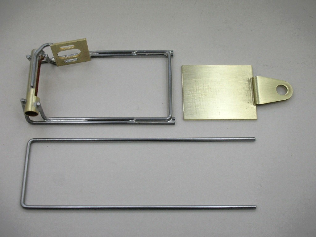
Working on my center section meant cutting up a used Parma drop arm. New Parma arm shown for reference:
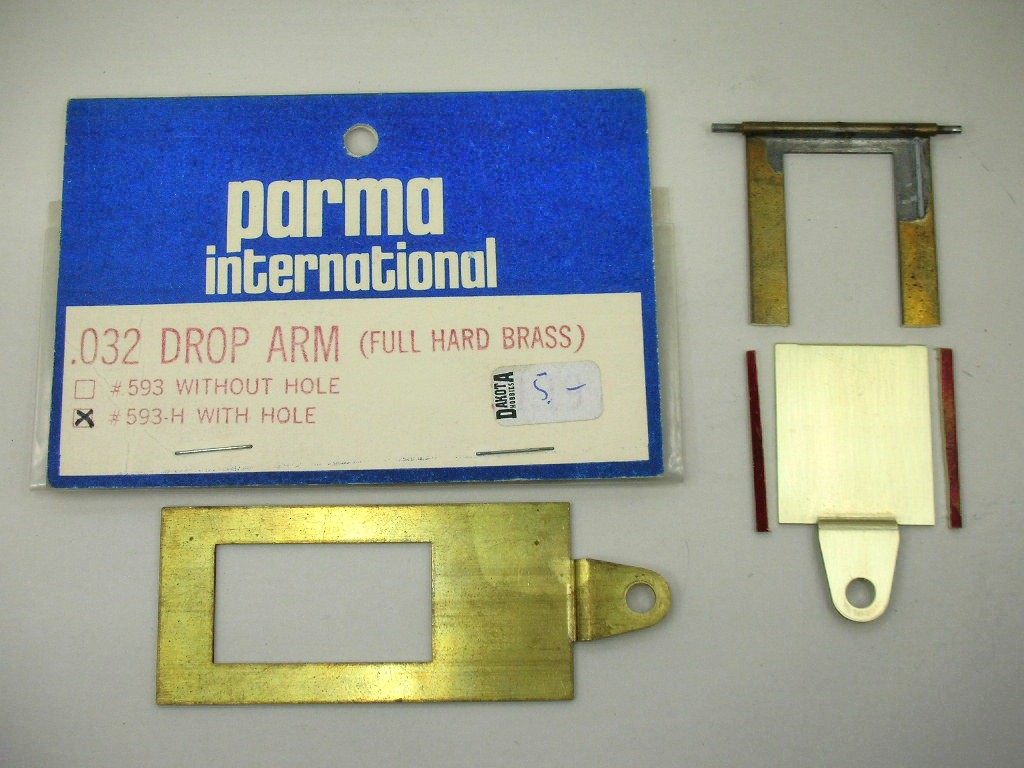
The parts ready ready for soldering to make the chassis into one lump:
- Tex and Jaeger Team like this
Rick Thigpen
Check out Steve Okeefe's great web site at its new home here at Slotblog:
The Independent Scratchbuilder
There's much more to come...
#33
dc-65x
-
- Subscriber
-
- 7,204 posts Joined: 14-February 06
Grand Champion Poster
- Gender:Male
- Location:Captain Rick: The only vintage slot car nut in SW Oregon?
Posted 19 February 2026 - 08:41 PM
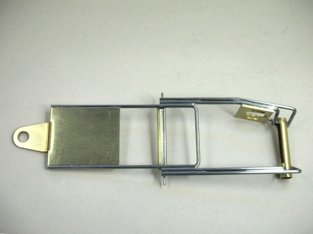
Everything soldered together:
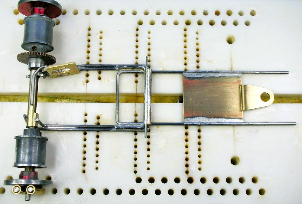
A 3/32" tube ISO hinge................
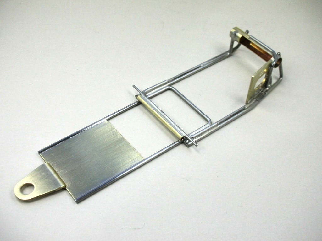
...........and .039" wire plumber upward stop are also installed:
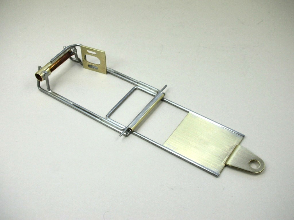
The ISO front end is next:
- vfr750, Tex, Slot Car Rod and 2 others like this
Rick Thigpen
Check out Steve Okeefe's great web site at its new home here at Slotblog:
The Independent Scratchbuilder
There's much more to come...
#34
Larry Horner
-

- Full Member
-
- 550 posts Joined: 18-March 17
Race Leader
- Gender:Male
- Location:San Francisco
Posted 20 February 2026 - 11:16 AM
Rick, I'm loving this design! But I have a general question about iso chassis. Is a design in which the entire front end drops together (front axle and guide) considered an iso? Thinking of Gene Hunting's anglewinder or the Dynamic Outlaws. I've always considered an iso chassis as having just the front axle float.
#35
dc-65x
-
- Subscriber
-
- 7,204 posts Joined: 14-February 06
Grand Champion Poster
- Gender:Male
- Location:Captain Rick: The only vintage slot car nut in SW Oregon?
Posted 20 February 2026 - 01:12 PM
Hi Larry,
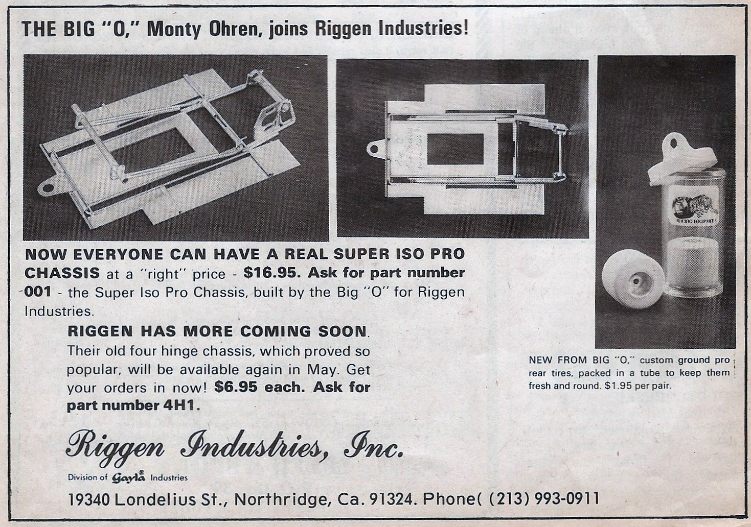
I'm sure there are various definitions of what an ISO chassis is. I just think of it as "ISO"lating the front wheels form the handling equation.....
For this project I'm thinking about this style vintage Pro style ISO that is isolating the front wheels:
- Tex, stoo23, Slot Car Rod and 1 other like this
Rick Thigpen
Check out Steve Okeefe's great web site at its new home here at Slotblog:
The Independent Scratchbuilder
There's much more to come...
#36
munter
-

- Full Member
-
- 1,059 posts Joined: 11-April 08
Checkered Flag in Hand
- Gender:Male
- Location:Napier, New Zealand
Posted 20 February 2026 - 03:32 PM
I'm sure there are various definitions of what an ISO chassis is. I just think of it as "ISO"lating the front wheels form the handling equation.....
I think kind of the opposite....where the drive line and guide are isolated from the rest of the chassis....but what about that term isofulcrum, perhaps just a Cox term.
I have built a few chassis which hinge from the front, sometimes from the axle but always from close to it.
John Warren
Slot cars are my preferred reality
#37
Bill from NH
-

- Full Member
-
- 15,317 posts Joined: 02-August 07
Age scrubs away speed!
- Gender:Male
- Location:New Boston, NH
Posted 20 February 2026 - 04:34 PM
Some ISOs are hinged behind the rear axle.
"But I have a general question about iso chassis. Is a design in which the entire front end drops together (front axle and guide." Larry, I have a chassis down cellar, made by my friend Dan O'Neil during the mid-70s, that is hinged at the middle with the front axle & guide attached. He never called it an ISO, but it didn't like glue racing either, My friend Dan is the same guy who build a full sidewinder using a highly modified B-can. He often thought outside the box.
Bill Fernald
I intend to live forever! So far, so good.
I intend to live forever! So far, so good.
#38
Mbloes
-
- Subscriber
-
- 633 posts Joined: 19-April 12
Race Leader
- Gender:Male
- Location:Los Angeles, CA
Posted 20 February 2026 - 08:50 PM
Just one more reason why Riggen is my favorite classic company.
Mike Bloes
#39
Don Weaver
-

- Subscriber
-
- 1,908 posts Joined: 26-October 07
Checkered Flag in Hand
- Gender:Male
- Location:Lexington. SC
Posted 21 February 2026 - 03:29 PM

Rick,
How do you measure the bend points of the "U" to fit the chassis precisely? Also, what if the "U" was an inside fit? Thanks...
Don
Don Weaver
A slot car racer who never grew up!
The supply of government exceeds demand.
L.H. Lapham
If the brain-eating amoeba invades Washington
it will starve to death...
#40
dc-65x
-
- Subscriber
-
- 7,204 posts Joined: 14-February 06
Grand Champion Poster
- Gender:Male
- Location:Captain Rick: The only vintage slot car nut in SW Oregon?
Posted 21 February 2026 - 09:10 PM
I'll tell you how Don, persistence and lots of extra piano wire. Steve Okeefe is a master at precision wire bending.....me, not so much. 
To make a U-bend to certain dimension:
First make a 90 degree bend and check it with a square.
Set dial calipers to the finished dimension needed plus or minus (depending if it's an inside or outside piece) the amount I think the bend will take up, say I start with .070" as the "magic number".
Place the piece in the calipers and mark for the next bend.
Measure the piece and it is usually off by some amount.
The difference between what you want and what you got is the amount you adjust your calipers by and try again. 
I know, this method sucks but at least I'm doing my part to keep K&S Metals in business!
- Tex, Eddie Fleming and mickey thumbs like this
Rick Thigpen
Check out Steve Okeefe's great web site at its new home here at Slotblog:
The Independent Scratchbuilder
There's much more to come...
#41
dc-65x
-
- Subscriber
-
- 7,204 posts Joined: 14-February 06
Grand Champion Poster
- Gender:Male
- Location:Captain Rick: The only vintage slot car nut in SW Oregon?
Posted 24 February 2026 - 08:32 PM
I've finally got the center section in one lump:
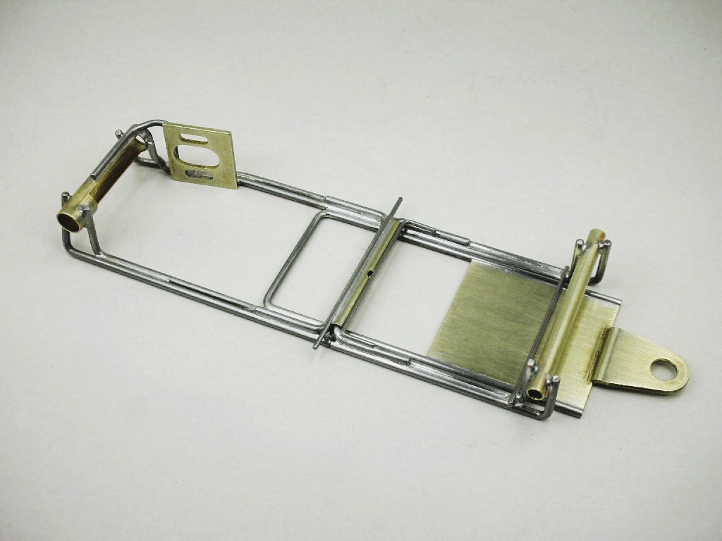
ISO.....attention!
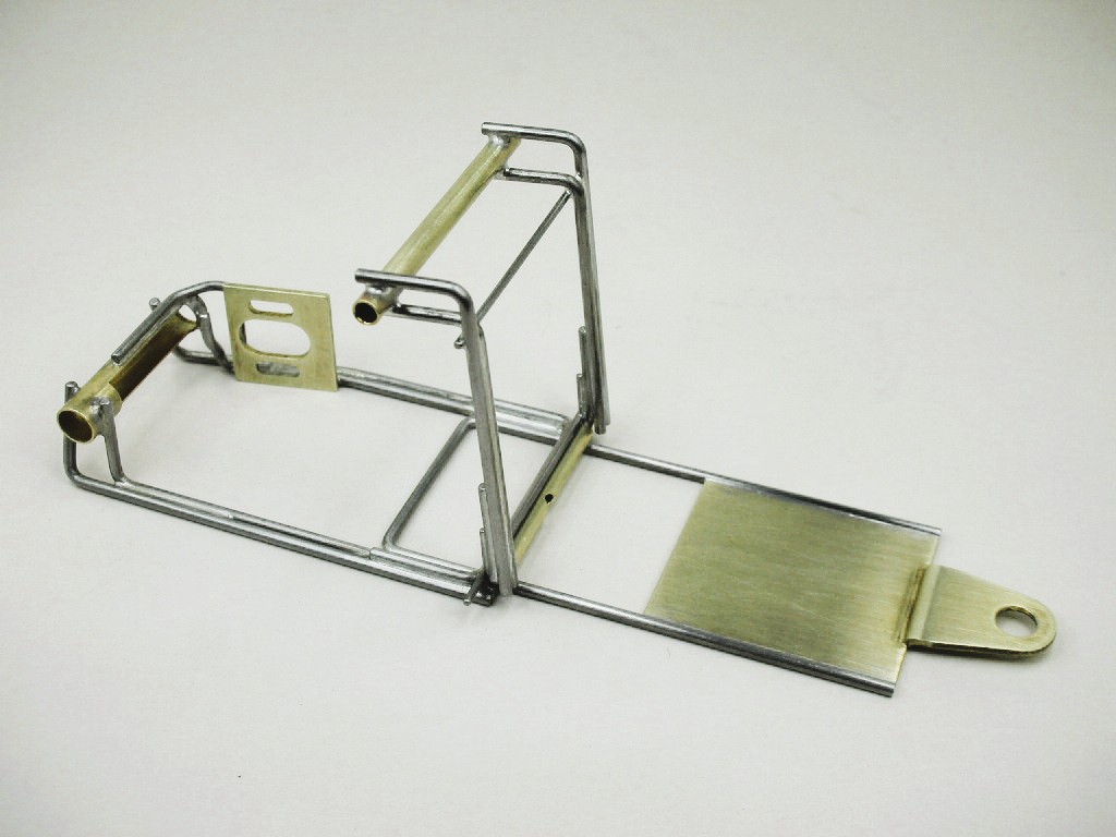
I used Kapton tape here and there to keep from soldering everything solid by mistake:
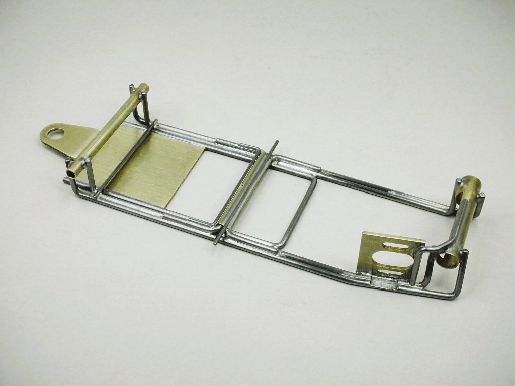
I still need to add a spring wire for the ISO front end:
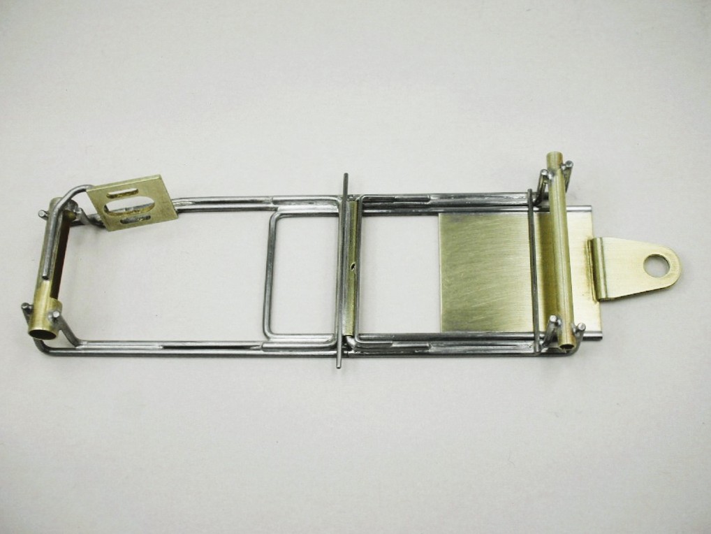
Plumber rails and front bumper are next:
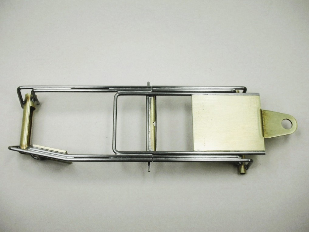
- Pablo, vfr750, Tex and 4 others like this
Rick Thigpen
Check out Steve Okeefe's great web site at its new home here at Slotblog:
The Independent Scratchbuilder
There's much more to come...
#42
SpeedyNH
-
- Full Member
-
- 820 posts Joined: 18-July 15
Old Engineer
- Gender:Male
- Location:Cow Hampshire
Posted 25 February 2026 - 07:55 AM
i still think that the joints could use some wire ties.
- John Luongo likes this
Steve Lang
#43
dc-65x
-
- Subscriber
-
- 7,204 posts Joined: 14-February 06
Grand Champion Poster
- Gender:Male
- Location:Captain Rick: The only vintage slot car nut in SW Oregon?
Posted 02 March 2026 - 01:42 PM
The plumber rails on the Owl Chump Stocker chassis are not hinged. They are soldered directly to the center section.
The original Stocker chassis:
The finished chassis ready to hang all the other goodies on:
This design doen't use any hinges for the plumber or pans. All the movement is obtained by flex. Here's a closeup:


My chassis in the jig with plenty of Kapton tape to stop unwanted solder flow:
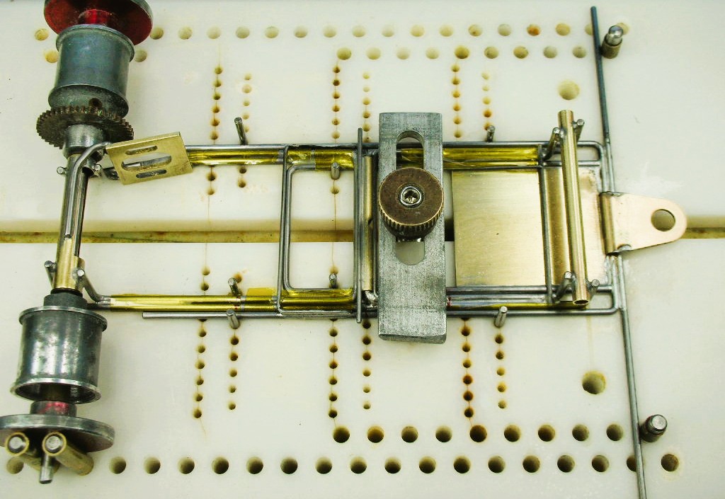
The installed plumber rails:
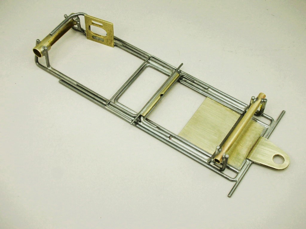
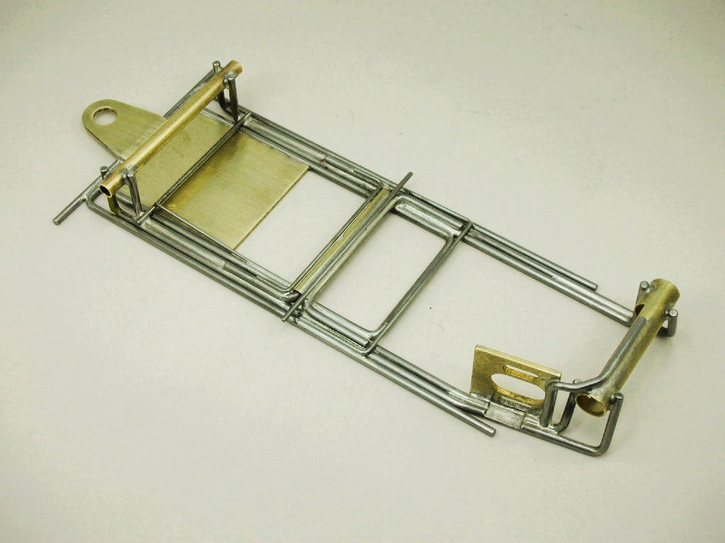
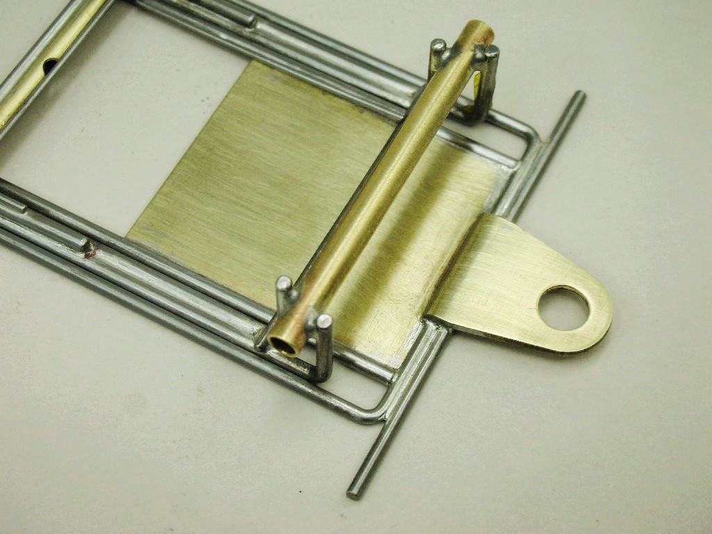
This is the attachment of the plumber rails on my new chassis mimicking the original Owl Chump stocker:
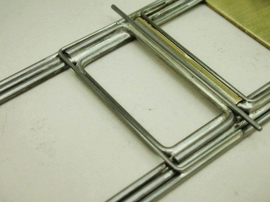
An .032" U-brace connects the 2 rails together in the rear:
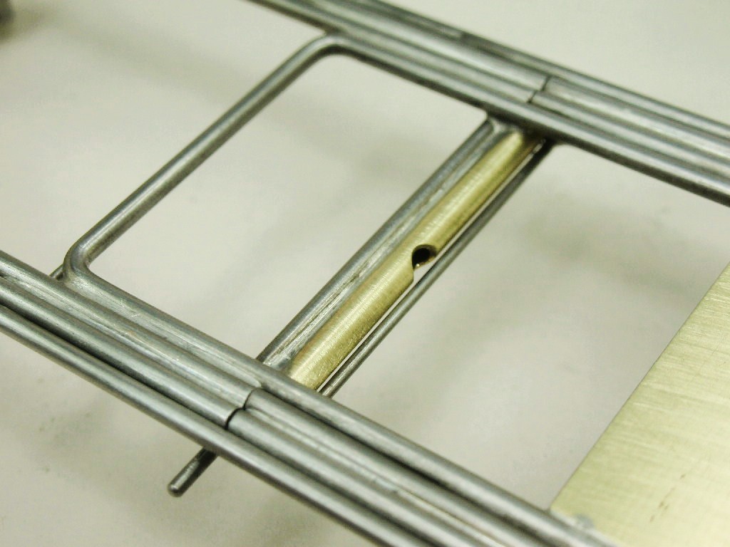
I also added a "blow hole" in the ISO hinge tube to blow out any water and acid flux to prevent it from rusting solid over time:
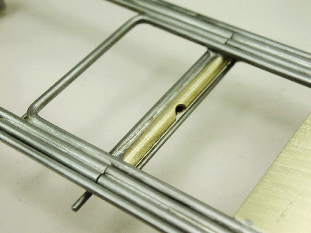
Got to make sure it is OK when it's tossed into the landfill. I'm 76 years old and my only son is not a vintage slot car guy.
- vfr750, Tex, SpeedyNH and 3 others like this
Rick Thigpen
Check out Steve Okeefe's great web site at its new home here at Slotblog:
The Independent Scratchbuilder
There's much more to come...
#44
Don Weaver
-
- Subscriber
-
- 1,908 posts Joined: 26-October 07
Checkered Flag in Hand
- Gender:Male
- Location:Lexington. SC
Posted 02 March 2026 - 04:58 PM
Got to make sure it is OK when it's tossed into the landfill.
If I wasn't 80 I would apply for the job 
Don Weaver
A slot car racer who never grew up!
The supply of government exceeds demand.
L.H. Lapham
If the brain-eating amoeba invades Washington
it will starve to death...
#45
Bill Breck
-

- Full Member
-
- 172 posts Joined: 21-October 10
Mid-Pack Racer
- Gender:Male
- Location:Middle TN
Posted 02 March 2026 - 09:43 PM
The plumber rails on the Owl Chump Stocker chassis are not hinged. They are soldered directly to the center section.
The original Stocker chassis:
My chassis in the jig with plenty of Kapton tape to stop unwanted solder flow:
The installed plumber rails:
This is the attachment of the plumber rails on my new chassis mimicking the original Owl Chump stocker:
An .032" U-brace connects the 2 rails together in the rear:
I also added a "blow hole" in the ISO hinge tube to blow out any water and acid flux to prevent it from rusting solid over time:
Got to make sure it is OK when it's tossed into the landfill.
I'm sure there's plenty of guys here on Slotblog who would love to have one of your chassis or complete cars.
#46
dc-65x
-
- Subscriber
-
- 7,204 posts Joined: 14-February 06
Grand Champion Poster
- Gender:Male
- Location:Captain Rick: The only vintage slot car nut in SW Oregon?
Posted 03 March 2026 - 11:57 AM
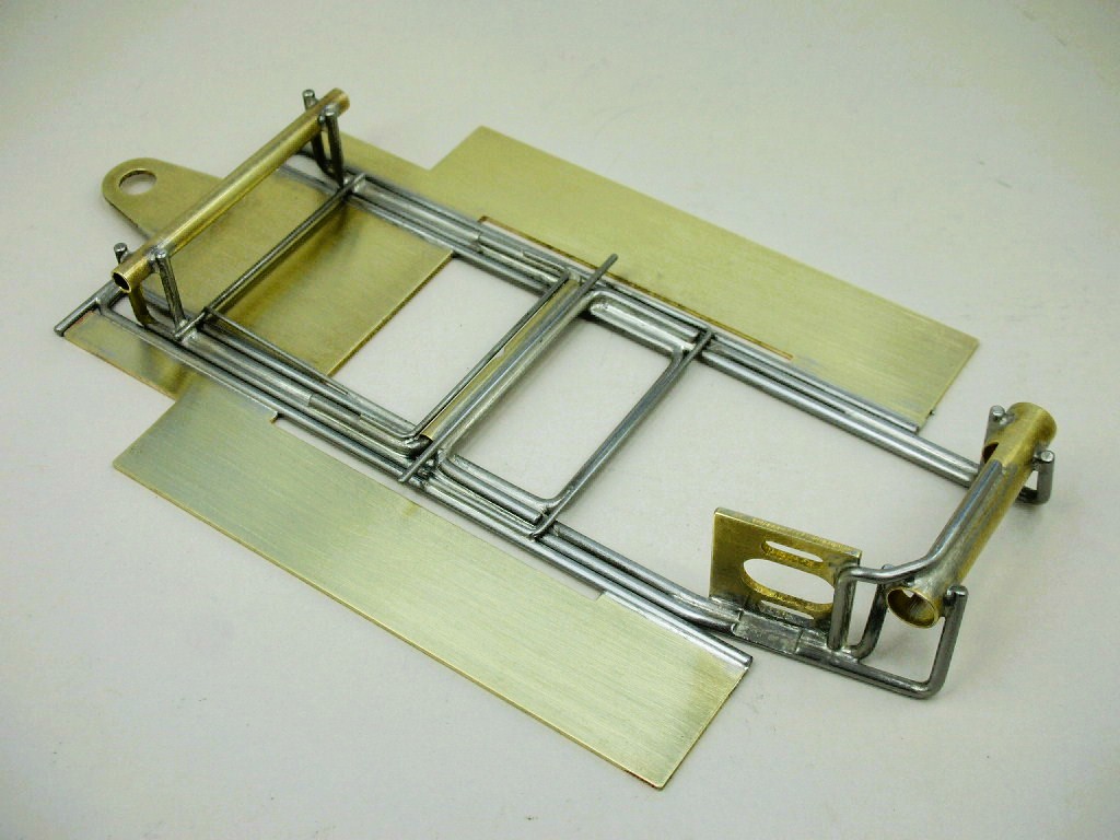
Clamps, clamps and more clamps. I have 2 locking the center section down, 1 each on the plumber and pans:
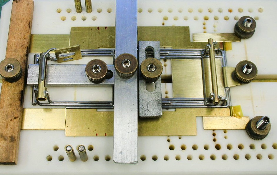
I also locked down 4 brass bits I used to drag excess solder off the pans as you can see below:
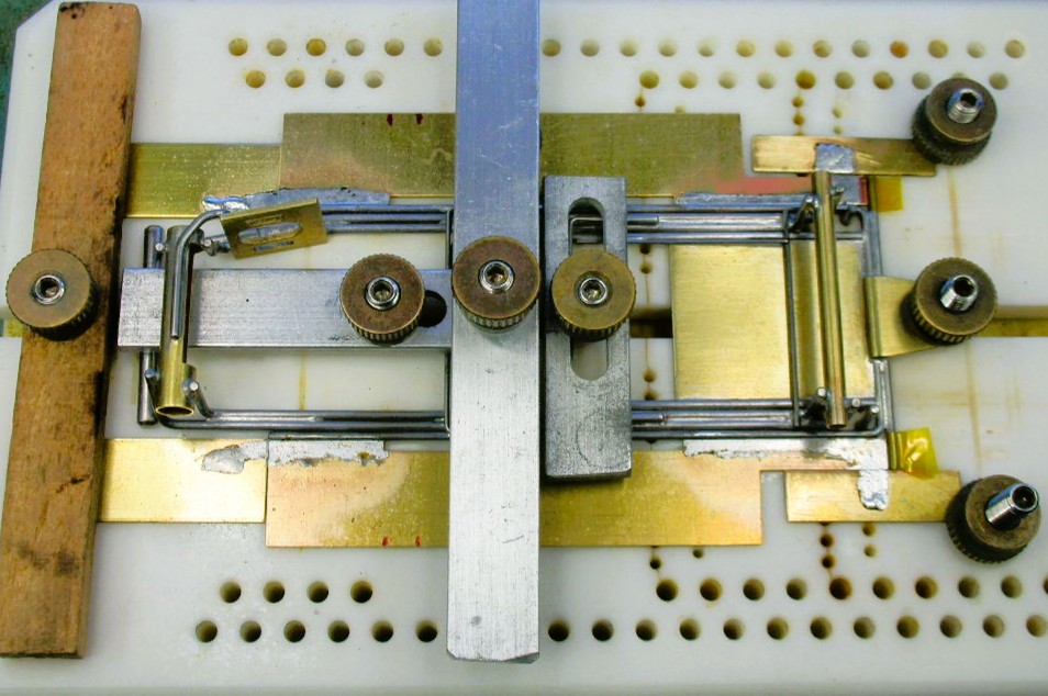
The chassis all scrubbed up:
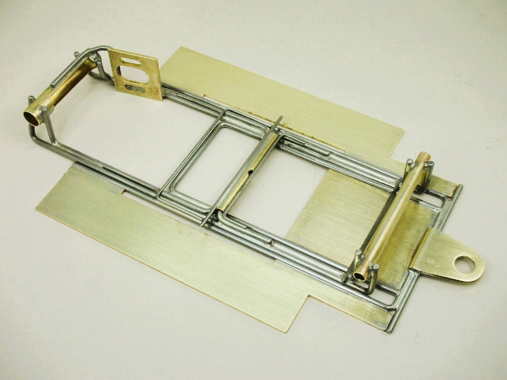
The body mounts are all that's left followed by a WD40 soak and polishing:
- Pablo, vfr750, stoo23 and 3 others like this
Rick Thigpen
Check out Steve Okeefe's great web site at its new home here at Slotblog:
The Independent Scratchbuilder
There's much more to come...
#47
Brian Czeiner
-
- Full Member
-
- 601 posts Joined: 04-March 08
Race Leader
- Gender:Male
- Location:Tyler, TX
Posted 03 March 2026 - 06:01 PM
I just noticed you make a hole to oil the drop tongue but not the front axle. Is this to be period correct or something else?
If it's not a Caveman, It's HISTORY! Support Your local raceways!
#48
dc-65x
-
- Subscriber
-
- 7,204 posts Joined: 14-February 06
Grand Champion Poster
- Gender:Male
- Location:Captain Rick: The only vintage slot car nut in SW Oregon?
Posted 03 March 2026 - 08:19 PM
Brian, I try to add a "blow hole" to any closed ended hinge. I can flush out any acid flux and water, then add oil to prevent it from rusting up solid. That's why I added one to my ISO front axle hinge.
I also added a "blow hole" in the ISO hinge tube to blow out any water and acid flux to prevent it from rusting solid over time:
- vfr750, munter, Alchemist and 1 other like this
Rick Thigpen
Check out Steve Okeefe's great web site at its new home here at Slotblog:
The Independent Scratchbuilder
There's much more to come...
#49
Alchemist
-

- Full Member
-
- 2,823 posts Joined: 11-November 09
Posting Leader
- Gender:Male
- Location:Far, far away
Posted 04 March 2026 - 03:36 PM
Hi Rick,
Incredible detail(s)!
Such craftsmanship!
Thanks for sharing Rick.
Ernie
Ernie Layacan
#50
dc-65x
-
- Subscriber
-
- 7,204 posts Joined: 14-February 06
Grand Champion Poster
- Gender:Male
- Location:Captain Rick: The only vintage slot car nut in SW Oregon?
Posted 16 March 2026 - 08:06 PM
Thank you Ernie
I've been vacilating on how to properly mount this scale body on my Pro car style chassis.
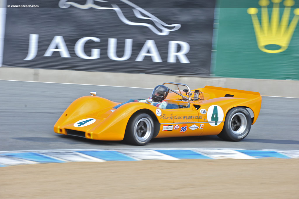
The McLaren M6, and many race cars of the era, have lower body sides that gracefully curve under:
The very bottom of the body is 2 3/4" wide, then about 1/4" up increases to a little over 2 7/8". I decided to use some rectangular tube to hold the pin tubes and support the lower edge of the body:
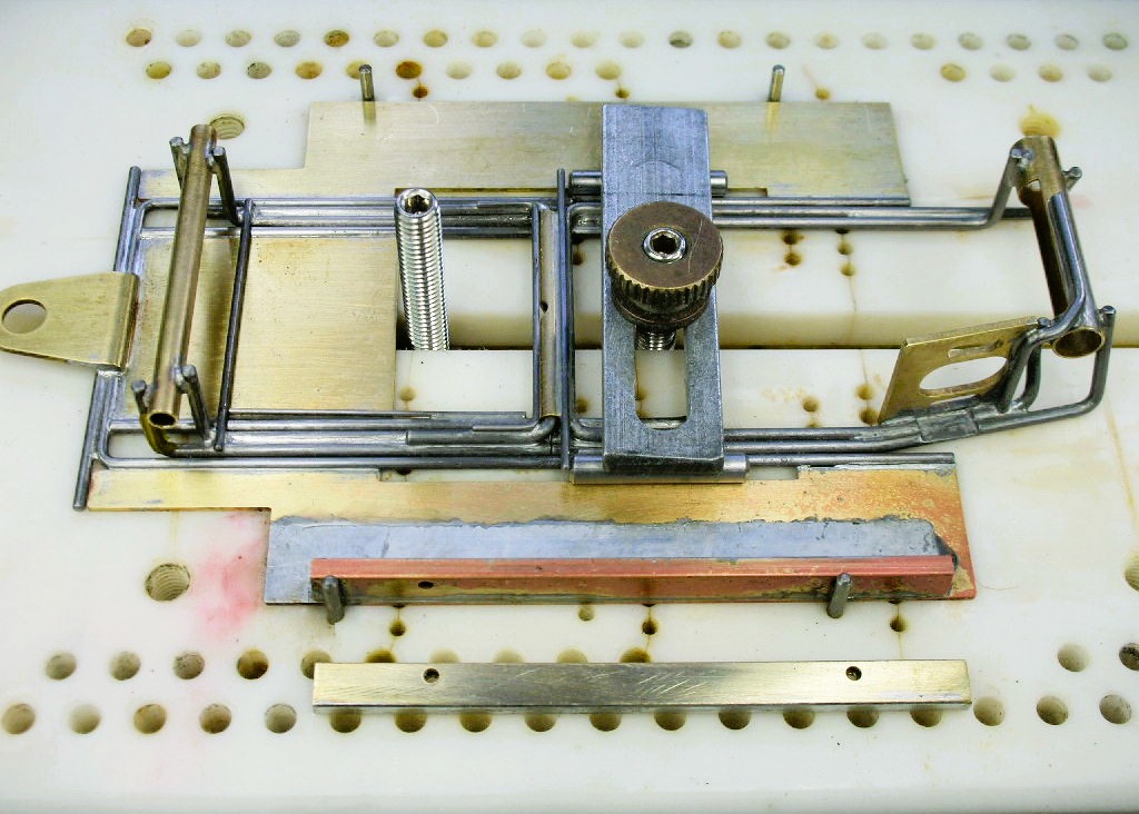
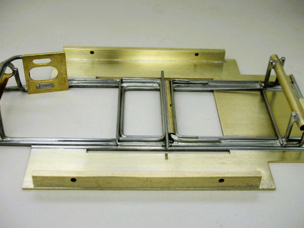
The body sides needed support at the pin tubes too. I mocked up this arrangement:
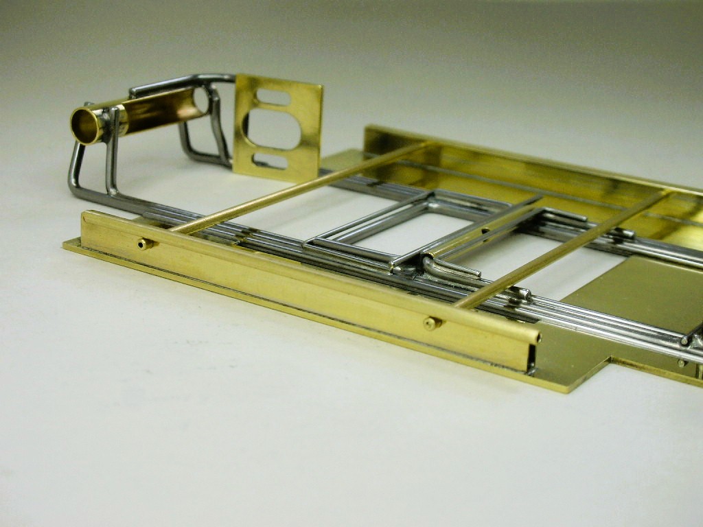
It seems to really do the trick:
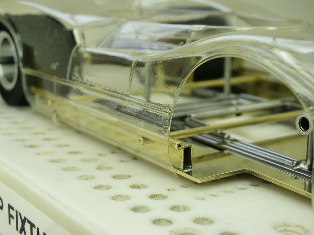
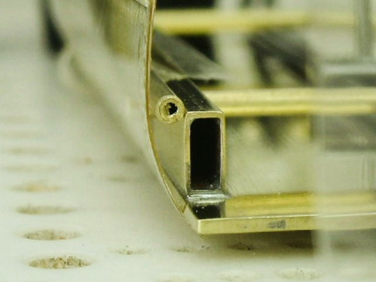
Time to solder this all up........
- vfr750, Tex, Fergy and 9 others like this
Rick Thigpen
Check out Steve Okeefe's great web site at its new home here at Slotblog:
The Independent Scratchbuilder
There's much more to come...




