Jump to content


Photo

Building my first D3 Hardbody Group C car


  • Please log in to reply
86 replies to this topic

#26 DeanJ

DeanJ

    Backmarker

  • Full Member
  • PipPip
  • 95 posts
  • Joined: 13-March 26
  • Gender:Male
  • Location:SoCal

Posted 01 April 2026 - 05:04 PM

I found it nearly impossible to keep the rods from tarnishing or flat out starting to rust without keeping them lubed with oil or DeoxIT D100. I remove what rust has started by running the wire wheel over it to get it clean again.
How do you all manage it? Theres days when I wont work on it, and now just sit it on a bag, lubed.

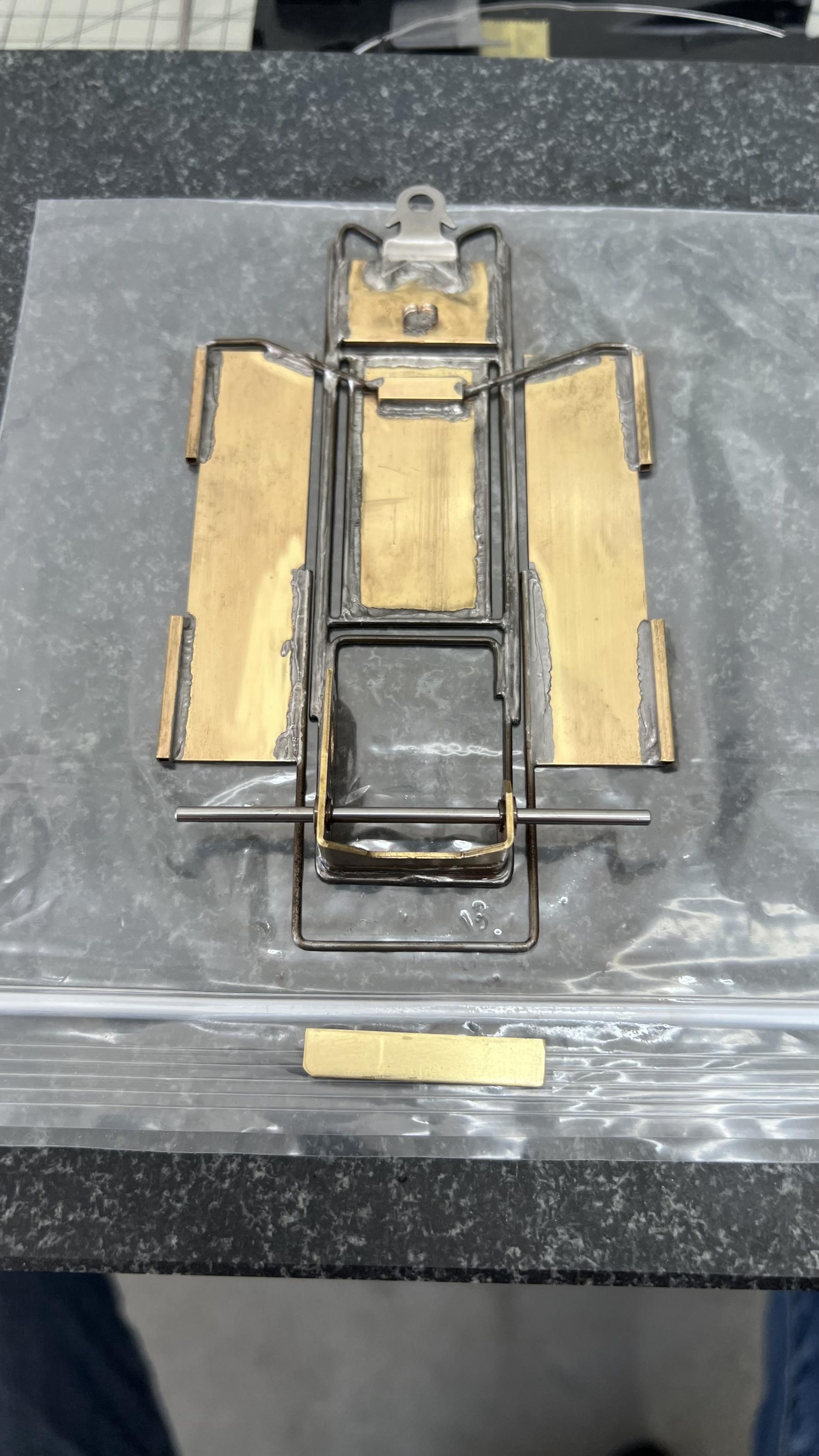
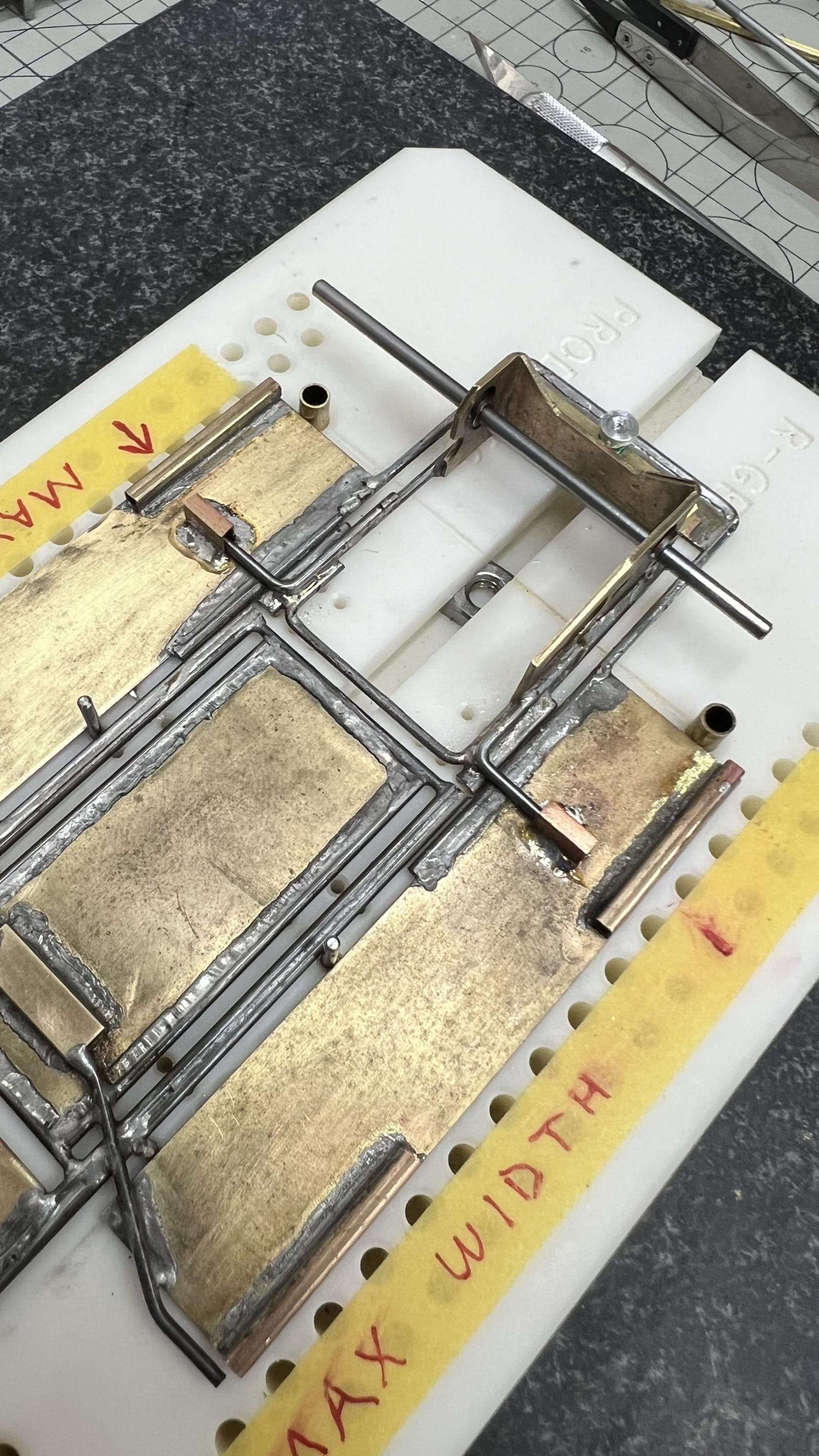
Im ready to solder the bottom rear platform in place thatll hold the suspension spring - its a piece of .032. Once thats done Ill attach a piece of .016 to the motor pod.

IMG_7999.jpeg
Dean John


#27 Cap Henry

Cap Henry

    CHR Cars

  • Subscriber
  • PipPipPipPipPipPipPip
  • 3,473 posts
  • Joined: 25-October 08
  • Gender:Male
  • Location:Bellevue, OH

Posted 01 April 2026 - 06:49 PM

Scrub it under water with comet and a scotch bright pad, itll remove/ neutralize the flux.
  • DeanJ likes this

#28 Bill from NH

Bill from NH

    Age scrubs away speed!

  • Full Member
  • PipPipPipPipPipPipPipPip
  • 15,316 posts
  • Joined: 02-August 07
  • Gender:Male
  • Location:New Boston, NH

Posted 01 April 2026 - 06:50 PM

Dean, pre-tin your piano wire & steel parts with 60/40 solder before you start to work with them. Piano wire in the old days by K&S & Sullivan were factory plated, so they didn't rust as quickly as today's.


  • DeanJ likes this
Bill Fernald
 
I intend to live forever!  So far, so good.  :laugh2:  :laugh2: 

#29 Keith Tanaka

Keith Tanaka

    Posting Leader

  • Full Member
  • PipPipPipPipPipPipPip
  • 2,965 posts
  • Joined: 18-June 06
  • Gender:Male
  • Location:West Covina, CA

Posted 04 April 2026 - 11:44 PM

Dean, here's a step by step instruction with photos showing how to clean and tin (solder) piano wire so it never rusts: https://socald3.smug...-step/i-hhxFFfm

Tinning piano wire (or brass sheet/strip) makes it much easier to solder strong solder joints.


Keith


  • vfr750, Bill from NH, grooverunner and 2 others like this

Team Rolling Hills circa '66-'68


#30 DeanJ

DeanJ

    Backmarker

  • Full Member
  • PipPip
  • 95 posts
  • Joined: 13-March 26
  • Gender:Male
  • Location:SoCal

Posted 05 April 2026 - 03:07 PM

Thanks Keith for the great write up! Thats exactly what Im doing, however I didnt tin the wire before using it so its a bit more difficult now.
Lesson learned.

I received my parts to complete the suspension so Ill likely get to it tomorrow.
I also have to move the square brass thats currently on the ends of the side pods, to on top of the side pods. With them in their current locations theres no movement with the body on.
Dean John

#31 DeanJ

DeanJ

    Backmarker

  • Full Member
  • PipPip
  • 95 posts
  • Joined: 13-March 26
  • Gender:Male
  • Location:SoCal

Posted 06 April 2026 - 08:39 PM

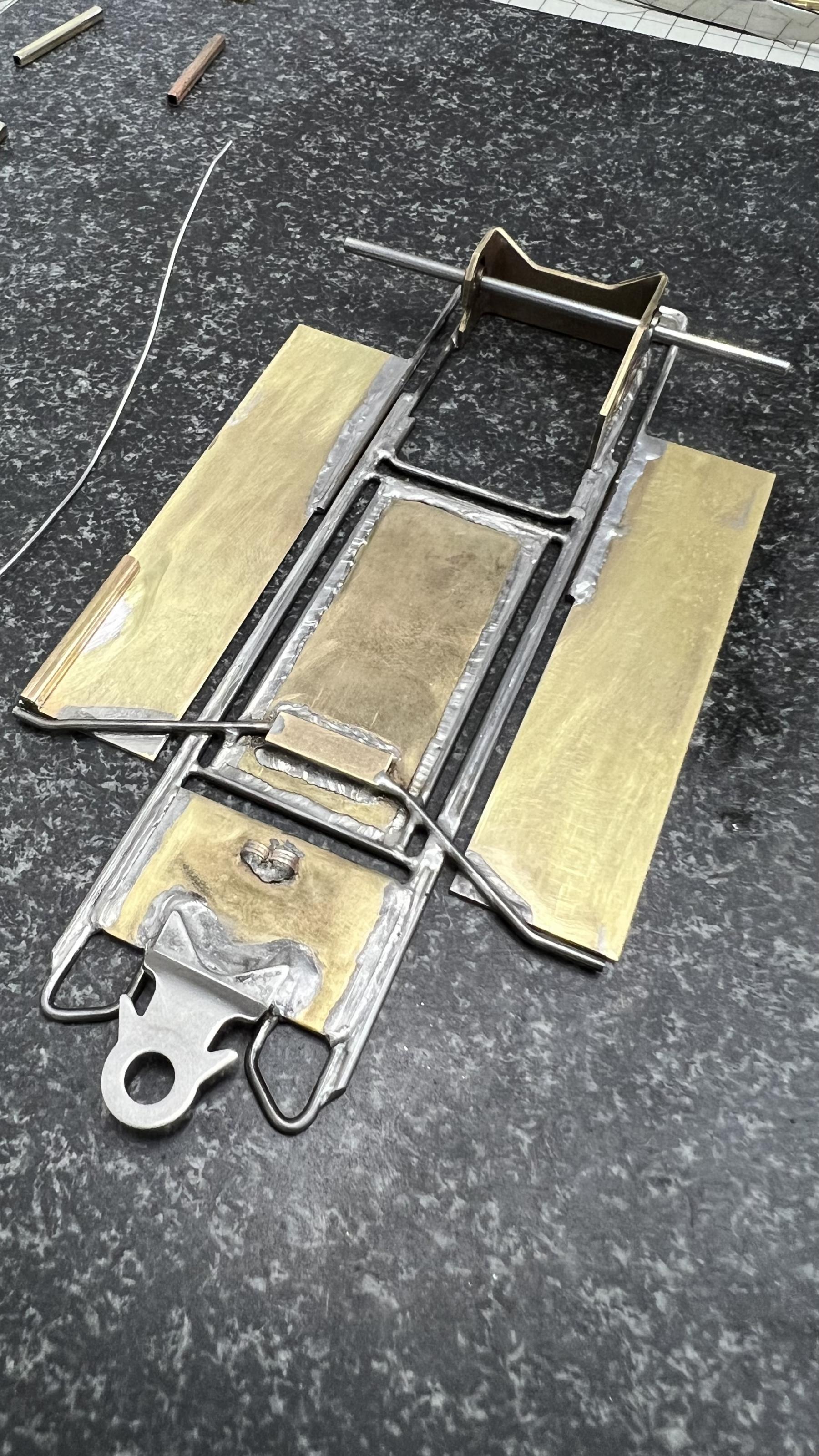
Update I was able to remove the square from the side pods, clean it all up and make it ready to solder on to the top of the pods. I think Ill add another piece once theyre in place, and use that for the body mounting not sure yet.

IMG_8007.jpeg

I also added the motor pod suspension platform and just need to drill the hole and screw in the shock shaft with spring. Ill try different springs based on how it goes, Red is Soft, Green is Medium, and Blue is Hard.

IMG_8008.jpeg
  • vfr750 likes this
Dean John

#32 DeanJ

DeanJ

    Backmarker

  • Full Member
  • PipPip
  • 95 posts
  • Joined: 13-March 26
  • Gender:Male
  • Location:SoCal

Posted 07 April 2026 - 09:53 PM

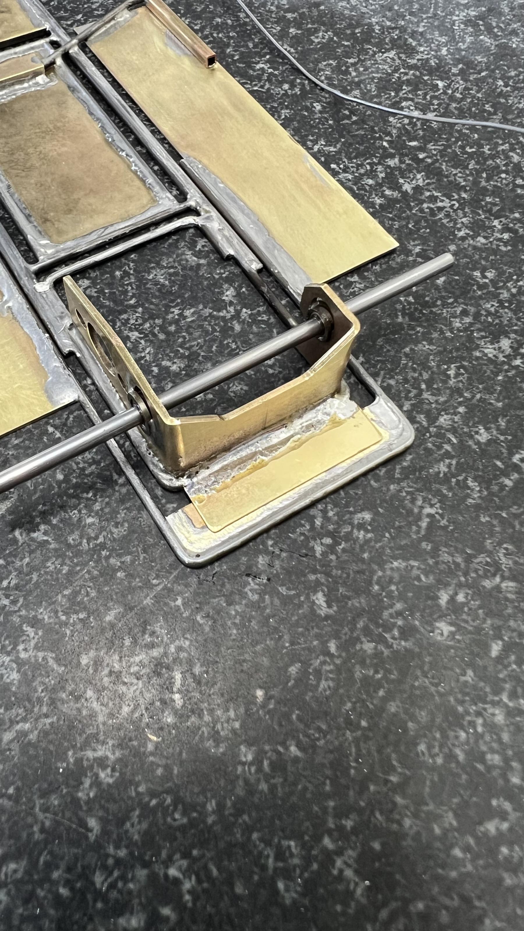
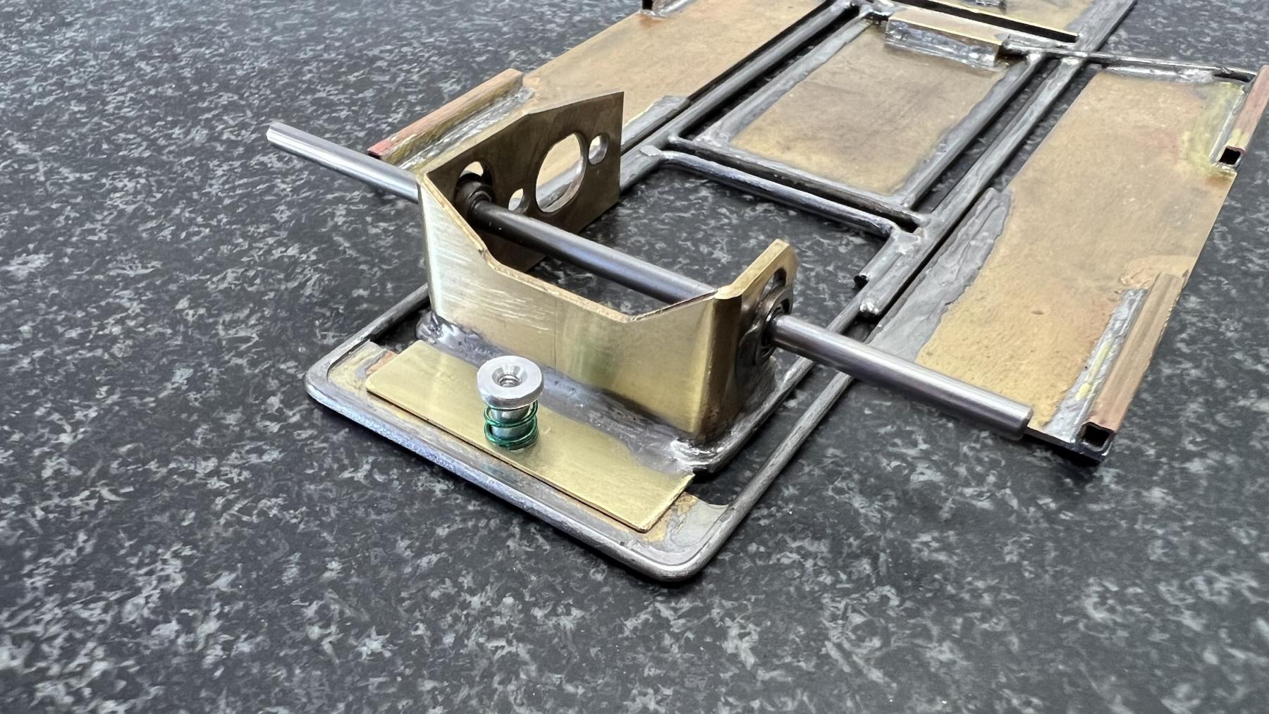
I have the rear suspension complete. I just have to clean it all up.

IMG_8015.jpeg

IMG_8017.jpeg

I also finished the side pods.
  • vfr750 likes this
Dean John

#33 DeanJ

DeanJ

    Backmarker

  • Full Member
  • PipPip
  • 95 posts
  • Joined: 13-March 26
  • Gender:Male
  • Location:SoCal

Posted 15 April 2026 - 05:09 PM

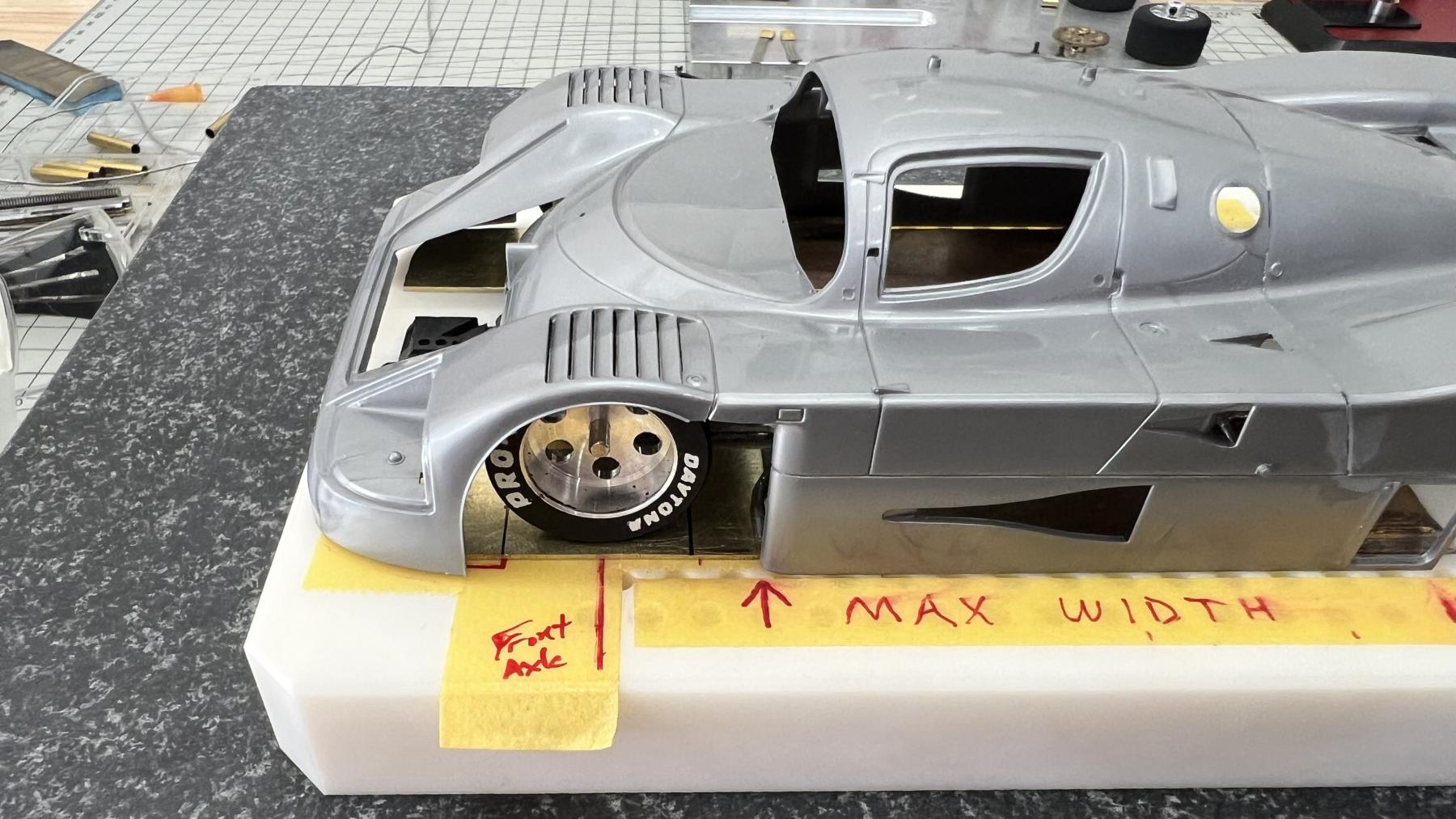
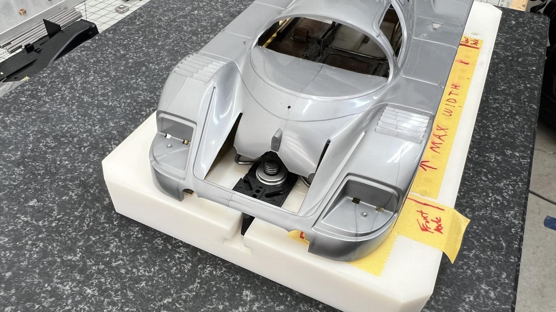
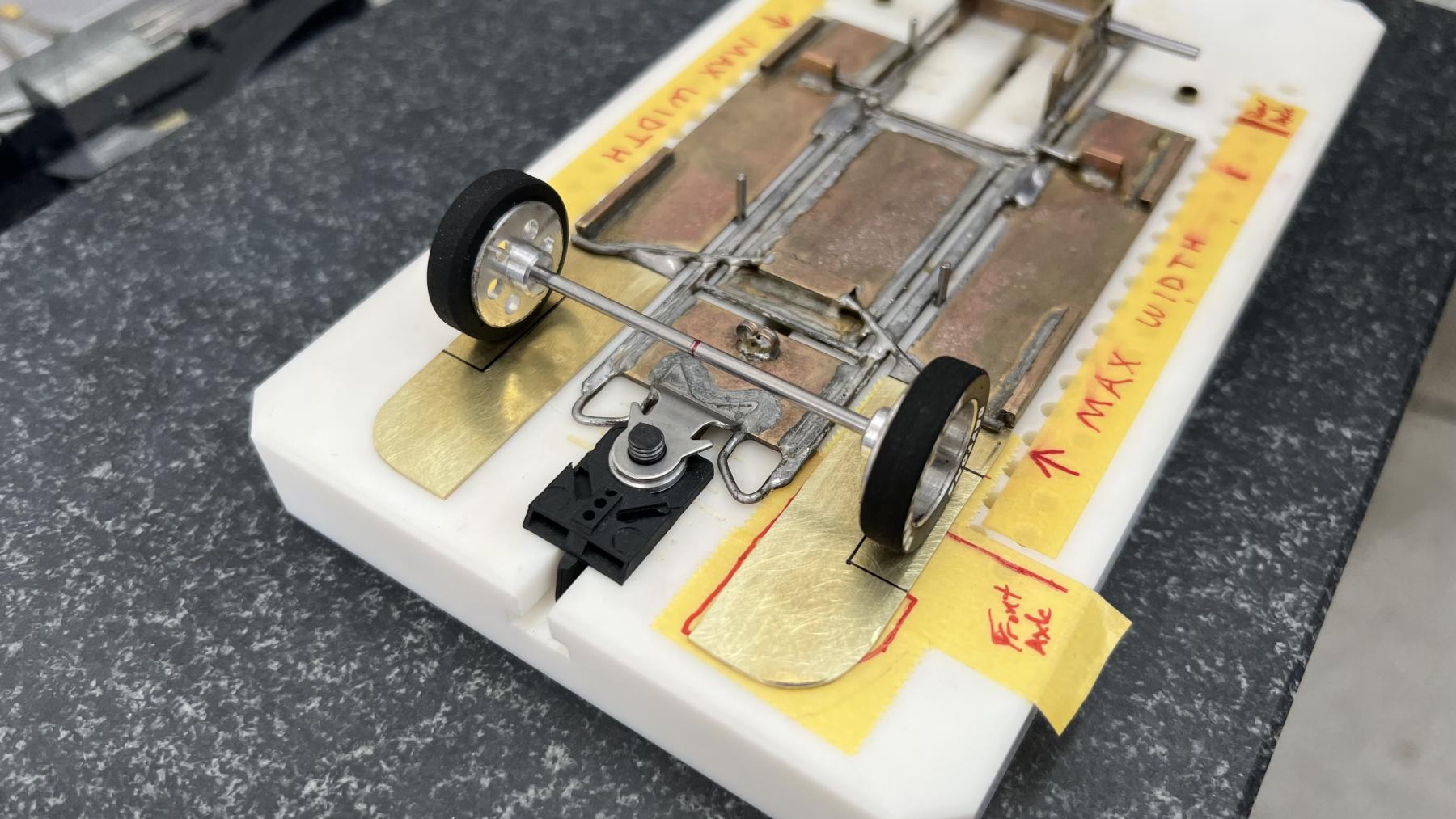
Work on the Front End has started. Ill make it part of the Center and Side Pods structurally. Ill then cut the Guide Pod loose and make it float.

IMG_8059.jpeg IMG_8061.jpeg IMG_8062.jpeg IMG_8063.jpeg

Ill then make the front axle support off the front end.
  • vfr750 and grooverunner like this
Dean John

#34 DeanJ

DeanJ

    Backmarker

  • Full Member
  • PipPip
  • 95 posts
  • Joined: 13-March 26
  • Gender:Male
  • Location:SoCal

Posted 16 April 2026 - 10:43 PM

After looking at all the chassis that raced, I couldn't see one clear design difference that made a winning car. With that said, I've decided not to make the guide pod float. I thought I saw 2 of the top 3 fastest cars did not have a guide that floated. And this being my very first car ever made, I'm more curious to see just what it does!


Front pans are ready to be installed - I'm using the small square tubing as a spacer.

IMG_8068.jpeg


  • vfr750 likes this
Dean John

#35 MG Brown

MG Brown

    Grand Champion Poster

  • Administrator
  • PipPipPipPipPipPipPipPip
  • 8,123 posts
  • Joined: 16-February 06
  • Gender:Male
  • Location:The Cumberland Plateau

Posted 17 April 2026 - 09:43 AM

Dean:


I am just following along with your build because in the part of the country where I live, there are no tracks holding Group C hardbody races. Because of this, I can't offer chassis-building advice. Sorry.


I will mention a couple of things that I have learned from building static Group C models...take them or leave them, your choice!


Tamiya makes lovely model kits- there is no question about that. But most of Tamiya's kits have multi-piece bodies. Hasegawa's Group C static models have one-piece bodies that might be more durable for slot car racing. Just a thought. Hasegawa offers the Sauber C9, Mazda 767B, Jaguar XJR8/9, Porsche 962C, Toyota 88/87-C 91/92CV, Nissan R89/90/91/92CP. Each marque has several works and privateer decal options.


 

10483649p.jpg  


10546785p.jpg


10373704p.jpg


10674887p.jpg


Small Rare-earth magnets can be used to secure a rear wing at the base; in a severe crash, the wing will detach rather than break. It is also easy to re-attach the wing when desired. I've only done this with static models, but I'm confident it could be adapted to your slot car if desired.


Best wishes for your project.


That's thirty minutes away. I'll be there in ten.


#36 DeanJ

DeanJ

    Backmarker

  • Full Member
  • PipPip
  • 95 posts
  • Joined: 13-March 26
  • Gender:Male
  • Location:SoCal

Posted 17 April 2026 - 01:35 PM

Thank you MGB for your input! Im slowly realizing this is a car that Ill only run at Electric Dreams, and races will go on for as long as the guys who make them are still able.

With regard to models and bodies, thanks again for your input. I am familiar with the brands you mention and their strengths and weaknesses, Im a builder also. I did notice the Tamiya C9 body is thin and brittle, and yes the rear engine cover is a separate piece.

 

I already glued the rear engine cover to the main body. I'm debating whether to put a layer of thin fiberglass on the inside of the body. Once the chassis is completed I'll weigh it and see how it compares to the weights of other cars - I think I want to be around 190g to start.


Dean John

#37 DeanJ

DeanJ

    Backmarker

  • Full Member
  • PipPip
  • 95 posts
  • Joined: 13-March 26
  • Gender:Male
  • Location:SoCal

Posted 17 April 2026 - 01:42 PM

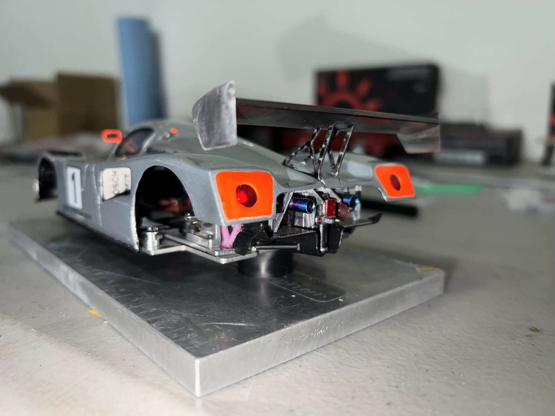
The magnet trick works excellent on a slot car! Heres the C291 I built a couple years ago that uses what you described.
IMG_0962.jpeg
  • Alchemist likes this
Dean John

#38 DeanJ

DeanJ

    Backmarker

  • Full Member
  • PipPip
  • 95 posts
  • Joined: 13-March 26
  • Gender:Male
  • Location:SoCal

Posted 20 April 2026 - 12:32 AM

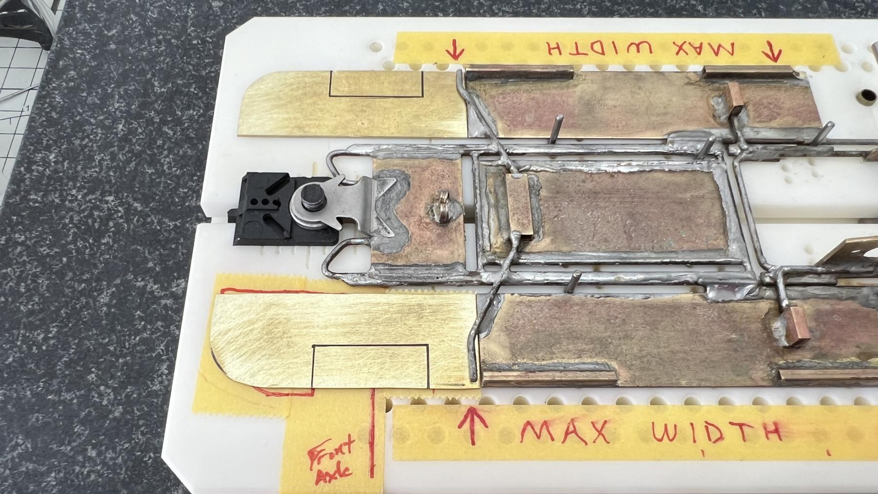
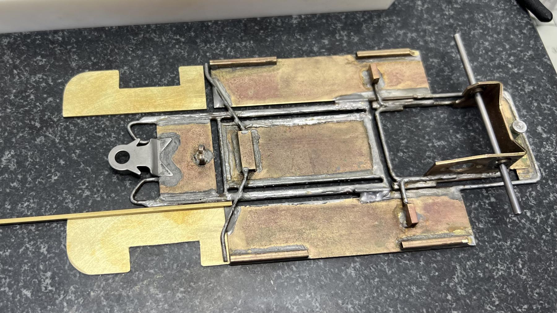
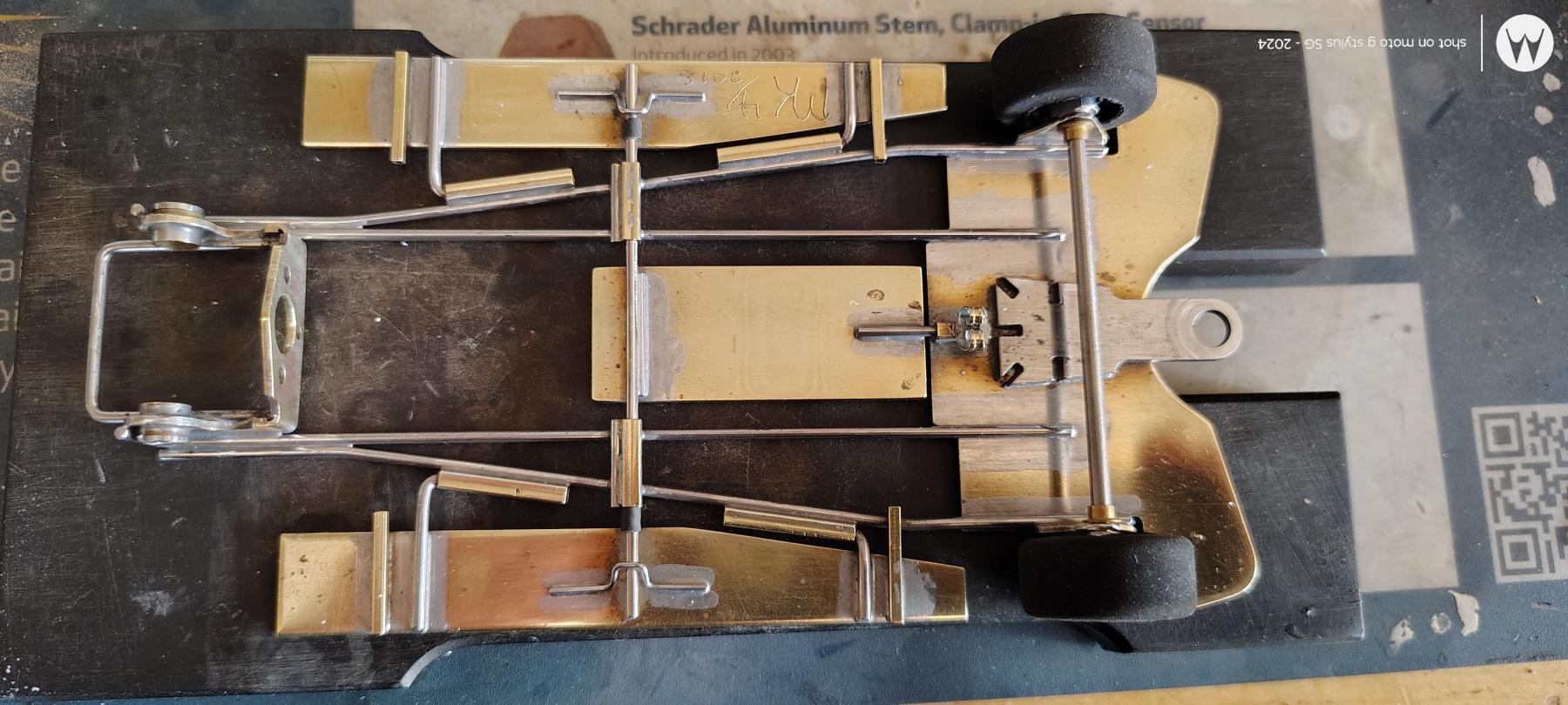
I managed to add the front pans, clean up the corners a little bit, tweak here and there, and properly tin all the wire on the back half of the chassis.


I have to decide how to mount the front axle - I have to put the body on and see how much room there is to play with. I'll likely go with a simple wire holding brass bushings on each side.


Ohh... and I had to make room for the spur gear! I could've used another motor with the pinion soldered at the end of the motor shaft, but why bother, just a little modification! I might add another wire going all the way around the back from pan to pan, just to be sure it won't break.


Next week is a 4 Hour Enduro race, I think... Should be a lot of fun showing up to race with this thing an not knowing how well it'll work!!


IMG_8075.jpeg


I started cutting the rear square tubing to make room for the body mounting hardware. I need to remove the front half of the tubing and then add rectangular with a slit cut into it. I'll use some kind of angle to glue to the body, not sure what yet.


Dean John

#39 MG Brown

MG Brown

    Grand Champion Poster

  • Administrator
  • PipPipPipPipPipPipPipPip
  • 8,123 posts
  • Joined: 16-February 06
  • Gender:Male
  • Location:The Cumberland Plateau

Posted 20 April 2026 - 02:53 AM

This has been a lot of fun to follow; some very creative ideas at work!


  • olescratch and DeanJ like this
That's thirty minutes away. I'll be there in ten.


#40 slotcarone

slotcarone

    Posting Leader

  • IRRA National Director
  • PipPipPipPipPipPipPip
  • 4,179 posts
  • Joined: 23-January 07
  • Gender:Male
  • Location:Dutchess County, NY

Posted 20 April 2026 - 10:10 AM

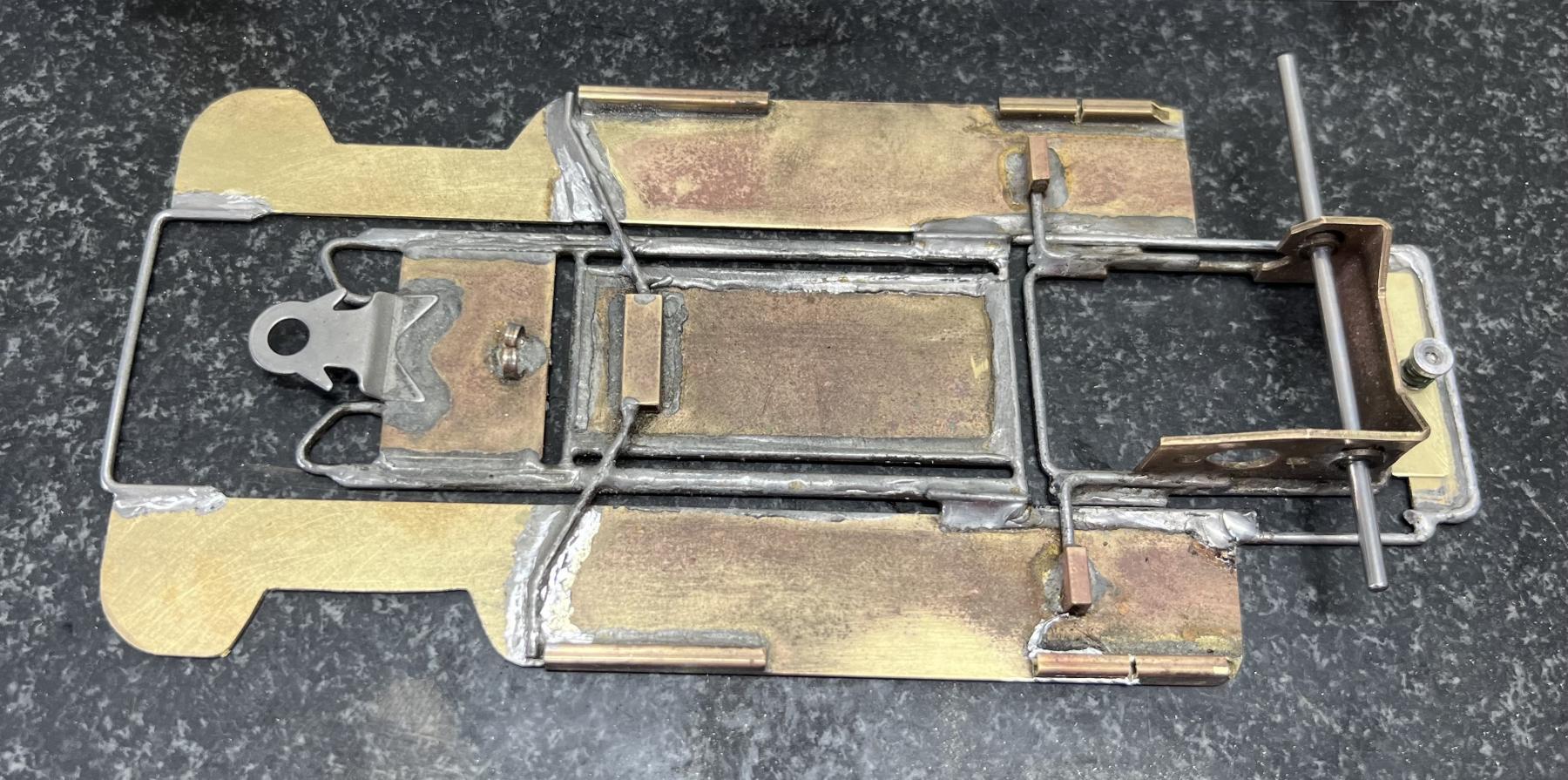
IMG_20250312_135437859_HDR.jpg Hi Dean and welcome! Just giving some constructive pointers here. Some of your solder joints look OK and some are not. What are you using for a soldering iron? Also what type of solder and acid are you using? As others have suggested you need to put that chassis in the sink to clean it. I have always used an SOS pad during and after the chassis build to clean the joints and prepare the metal for the next soldering steps. Works well. Do not use Brillo though. Here's a Retro chassis I built a few years ago.  :)


  • Pablo, Half Fast and JerseyJohn like this

Mike Katz

Scratchbuilts forever!!


#41 DeanJ

DeanJ

    Backmarker

  • Full Member
  • PipPip
  • 95 posts
  • Joined: 13-March 26
  • Gender:Male
  • Location:SoCal

Posted 21 April 2026 - 12:38 AM

Thanks Mike for the comments, but can you share which joints you feel are not OK? And can you expand on what it is you mean?


To clarify, some have been ground down and cleaned up, and some have not. I've gone heavy on some too, knowing I would clean it up after. In fact, I really don't care what it looks like at this stage, it's all going to get cleaned up! Once it's all soldered I'll scrub it in the sink with a toothbrush and some metal polish I purchased. I'm capable of making it shine like polished gold if needed, but that's not the goal here!


I use a Weller digital soldering station WE1010NA and have about 7 different tips I use for various things.


Dean John

#42 slotcarone

slotcarone

    Posting Leader

  • IRRA National Director
  • PipPipPipPipPipPipPip
  • 4,179 posts
  • Joined: 23-January 07
  • Gender:Male
  • Location:Dutchess County, NY

Posted 21 April 2026 - 06:55 AM

I looked at the Weller station you are using and it looks like it should be capable of soldering these chassis if you have the correct tip. You should be using what typically is referred to as a chisel tip although the tips listed for that unit are not called that. When I look at your pictures in post 23 many of the solder joints look ok but then in th4 later pictures I am guessing you added solder on top of what was already there. At that point the solder did not flow into the existing solder like it needs to do. Are you using any soldering acid? Most of the joints the solder did not flow and you can see the lumps in them. The idea is to get the solder into a liquid state to flow into the joint. If you look at my chassis picture those are the raw solder joints. Nothing has been removed from them. You can see the solder was a liquid and flowed into the pieces to hold them together. I am guessing you are feeding the solder into the tip as you are soldering? May I suggest just put the acid on the parts and then put some solder on the tip and then bring the tip to the work and let it flow. If you need more solder then after it cools then ad more acid to the work and solder onto the tip and solder that joint again still allowing the solder to flow and become part of the joint. Most of the joints on my chassis are done that way. Hope this helps. :)


Mike Katz

Scratchbuilts forever!!


#43 Jay Guard

Jay Guard

    Posting Leader

  • IRRA National Director
  • PipPipPipPipPipPipPip
  • 3,067 posts
  • Joined: 10-December 06
  • Gender:Male
  • Location:DeLand, FL

Posted 21 April 2026 - 09:43 AM

Dean:

What solder alloy are you using?  Preferred by most chassis builders is a rosin core Sn60/Pb40 or eutectic Sn63/Pb37 solder.  Other alloys, and especially the silver bearing ones, can take a lot more heat to get the joint to flow smoothly.  This can be especially difficult on thicker/larger flat brass pieces.  A larger tip often helps too as it has more mass and retains heat better.  Also, stay away from the lead-free low temp solders, they are just plain terrible to work with.


Jay Guard
IRRA Board of Directors (2022-Present),
Gator Region Retro Racing Director (2021-2025)
SERRA Co-Director (2009-2013)
IRRA BoD advisor (2007-2010)
Team Slick 7 member (1998-2001)
Way too serious Retro racer


#44 DeanJ

DeanJ

    Backmarker

  • Full Member
  • PipPip
  • 95 posts
  • Joined: 13-March 26
  • Gender:Male
  • Location:SoCal

Posted 21 April 2026 - 11:00 AM

Thanks Mike for the great write up on how to solder. Yes the Weller is more than capable of soldering brass and wire, and I have 4 different chisel tips of varying sizes. Rest assured the joints are soldered properly with acid.
Because I made the mistake of not tinning the wire before starting the process, Ive gone back here and there and reflowed with more, and added a little piece here and there also.

I guess I shouldve started out this thread with saying Im new to building a brass chassis, not new to soldering or building as Ive been soldering for over 30 years and building static models just as long.
  • team burrito likes this
Dean John

#45 slotcarone

slotcarone

    Posting Leader

  • IRRA National Director
  • PipPipPipPipPipPipPip
  • 4,179 posts
  • Joined: 23-January 07
  • Gender:Male
  • Location:Dutchess County, NY

Posted 21 April 2026 - 12:25 PM

While others talk about pretinning the work I have never done that at all. I never feel it is necessary. You say you added more solder, but it did not flow. It just built up on top of what was there already. To me it looks like the iron is not transferring the heat very well. Try my suggestion of putting the solder onto the tip and then to the work. Then the solder is a liquid already. Soldering a chassis is totally different than doing electrical work and requires different techniques. What type and size solder are you using? :)


  • team burrito likes this

Mike Katz

Scratchbuilts forever!!


#46 DeanJ

DeanJ

    Backmarker

  • Full Member
  • PipPip
  • 95 posts
  • Joined: 13-March 26
  • Gender:Male
  • Location:SoCal

Posted 21 April 2026 - 01:20 PM

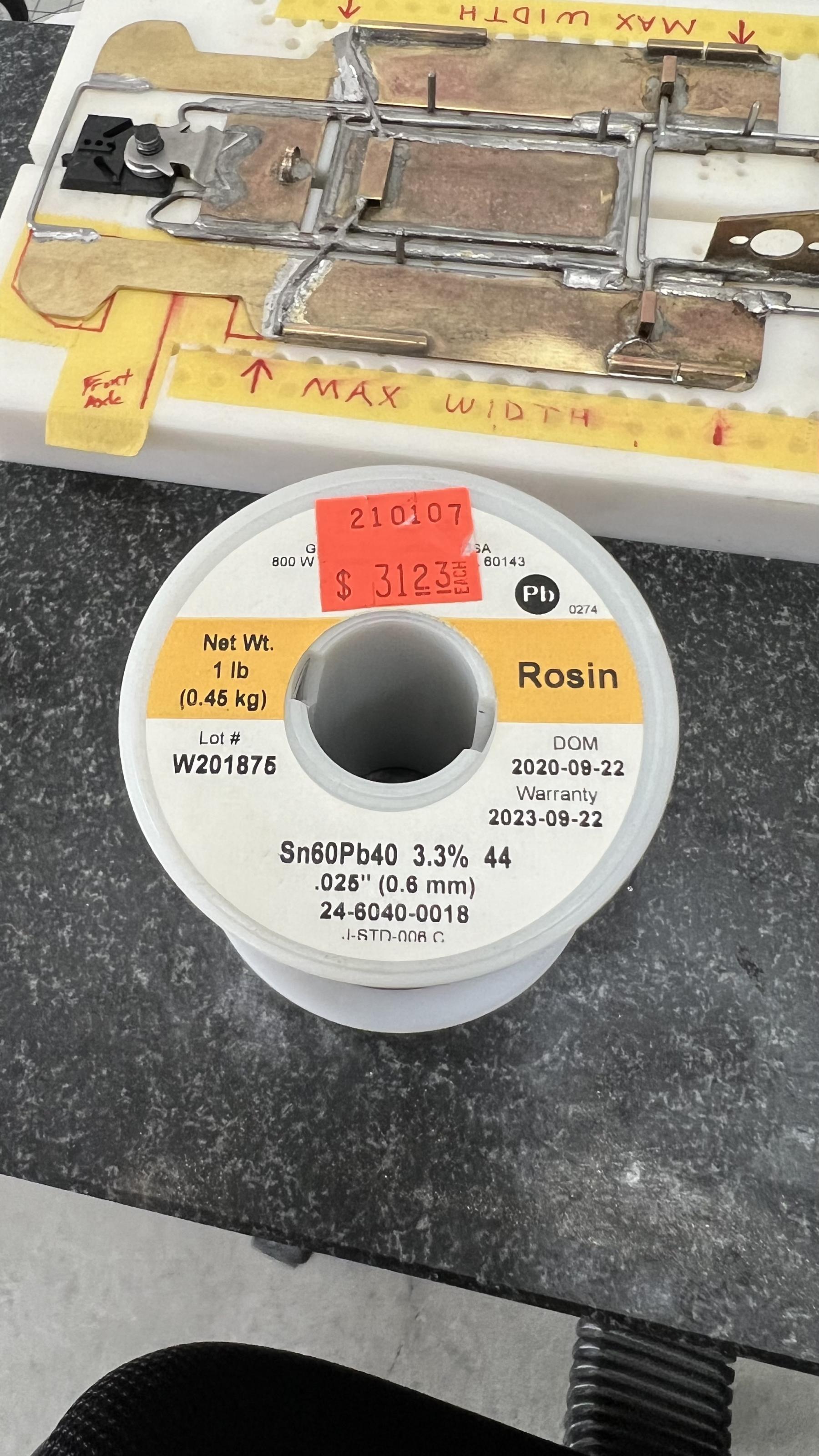
Thanks again guys for the constructive concern, appreciated! Again, the methods described by others is how the work is being done, its just a lot more solder than necessary in some places because I plan on going back over it and sanding it down. There are no places that solder was built up without flowing with what was already there, although it might look like it from the pictures.
Heres the solder Ive been using for the past 5 years.
IMG_8103.jpeg
Dean John

#47 DeanJ

DeanJ

    Backmarker

  • Full Member
  • PipPip
  • 95 posts
  • Joined: 13-March 26
  • Gender:Male
  • Location:SoCal

Posted 21 April 2026 - 01:21 PM

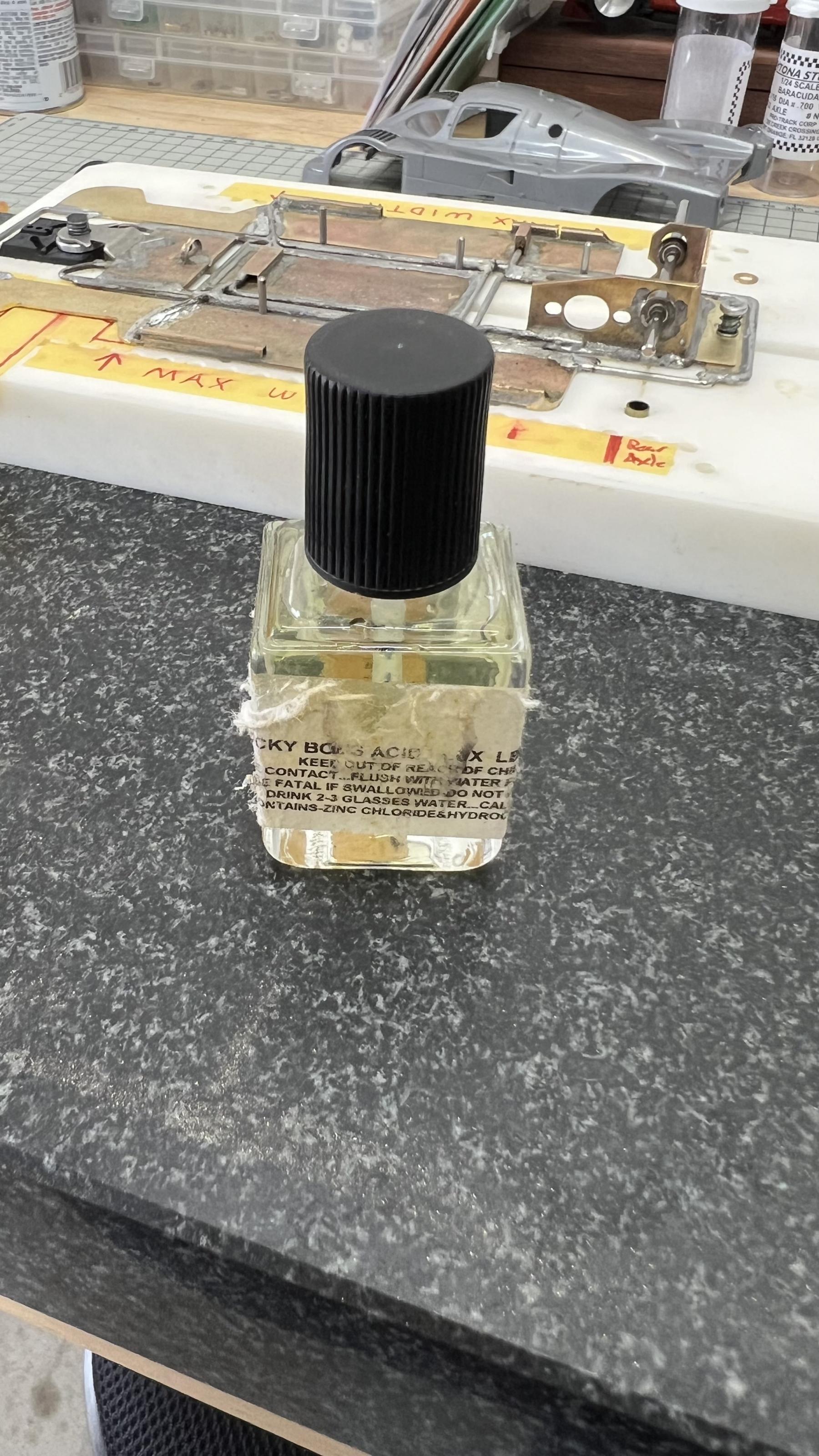
And heres the acidIMG_8104.jpeg
Dean John

#48 slotcarone

slotcarone

    Posting Leader

  • IRRA National Director
  • PipPipPipPipPipPipPip
  • 4,179 posts
  • Joined: 23-January 07
  • Gender:Male
  • Location:Dutchess County, NY

Posted 21 April 2026 - 03:36 PM

Not sure what solder you are using. 60/40 acid core solder works best. You really need to practice getting the solder to flow into the joints so that you are not sanding the solder off of the joints. That is how you make strong joints. On your next build give it a try! :)


  • team burrito likes this

Mike Katz

Scratchbuilts forever!!


#49 DeanJ

DeanJ

    Backmarker

  • Full Member
  • PipPip
  • 95 posts
  • Joined: 13-March 26
  • Gender:Male
  • Location:SoCal

Posted 21 April 2026 - 06:57 PM

Sorry but youre not getting it.

Perhaps if I put space between my sentences youll understand what I posted

Im trying to be as polite as possible when I say theres nothing about soldering I need to practice

The solder IS Flowing Into The Joint between the wire and brass, or between wires, wherever I soldered a joint.

The joints are strong because I allowed the solder to Flow between the material being soldered.
Dean John

#50 slotcarone

slotcarone

    Posting Leader

  • IRRA National Director
  • PipPipPipPipPipPipPip
  • 4,179 posts
  • Joined: 23-January 07
  • Gender:Male
  • Location:Dutchess County, NY

Posted 21 April 2026 - 08:02 PM

Now you are insulting me Dean. Just trying to help. My last post. Just look at the difference between the soldered joints on the chassis I posted and the chassis you posted. :)


  • grooverunner likes this

Mike Katz

Scratchbuilts forever!!


Electric Dreams Online Shop