Beautiful work on the motor boxes Steve. ![]() It would take me at least this many attempts to hopefully get ONE right.....and I wouldn't be able to duplicate it.
It would take me at least this many attempts to hopefully get ONE right.....and I wouldn't be able to duplicate it. ![]()
Steve is a true master at this

Posted 02 April 2016 - 08:45 PM
Beautiful work on the motor boxes Steve. ![]() It would take me at least this many attempts to hopefully get ONE right.....and I wouldn't be able to duplicate it.
It would take me at least this many attempts to hopefully get ONE right.....and I wouldn't be able to duplicate it. ![]()
Steve is a true master at this
Rick Thigpen
Check out Steve Okeefe's great web site at its new home here at Slotblog:
The Independent Scratchbuilder
There's much more to come...
Posted 10 April 2016 - 09:30 PM
The Center of Everything
Finishing up the motor box involves installing the motor bracket, axle tube and two piano wire braces.
Of course, the gears have to mesh properly, the motor has to clear the axle tube and the set screw on the rotating spur gear has to clear both the motor bracket and its brace. The motor box is by far the most complicated part of this chassis.
First thing to do is tin the piano wire that forms the motor box and then re-check all the bends for correct angle and the box itself for flatness on the block.
On the jig block, lay-in and center the jig axle & wheels, axle tube, bushings, spacers and spur gear. Lay-in the motor box and center relative to where the main rails will go, as shown in the drawings. Double-check to see the uprights are vertical and contact the axle tube where they are supposed to, then tack-solder the two uprights to the axle tube.
Lay-in the motor with the bracket attached, move it around until the pinion and spur mesh properly and the bracket is pushed up against the motor box rail. Loosen the motor mount screws if necessary and position the motor bracket itself to provide comfortable clearance between it and the set-screw on the spur gear, then re-tighten the motor mount screws. Double-check to see there is clearance between the motor and the axle tube, than tack-solder the bracket to the motor box rail.
The reason for tack-soldering here is primarily to avoid damaging the endbell. Despite being advertised as “unmeltable”, the Mura endbell… isn’t. The other reason for tack-soldering at this point is to allow easier re-positioning if necessary as you keep checking clearances and gear mesh.
Fashion a 1/16” piano wire bracket brace with a bend greater than 90 degrees. When installed as shown in the photos below, this brace must clear both the set-screw on the spur gear and the flange on the axle bushing. To do this, it will need to follow a downward and inward path from the motor bracket to the axle tube. When you get it shaped correctly, tin the part, check the angle and tack-solder into place.
Fashion a 1/16” piano wire can-side brace with a 90 degree bend. This brace should fit with the upright completely vertical and contacting the very end of the axle tube. When you get it shaped correctly, tin the part, check the angle and tack-solder into place.
Re-check all your clearances and gear mesh one more time. With the motor box still in the jig, remove the motor and finish soldering all the joints. At this point, everything should fit and look like this:
The main rails, by comparison, will be a piece-o-cake. Set up your R-Geo jig as shown:
Cut and fit 1/16” brass rod main rails and arrange them in four pairs; two pairs on each side spaced 1/16” apart. Lay-in a short piece of 1/16” brass rod at the front in between the two pairs of main rails as shown in the drawings. It is very important to keep the two sets of main rails parallel and spaced one inch apart for the drop arm.
Cut a piece of 5/32” brass tube two inches long for the front axle. Cut a wide (1-1/2”) notch in the top of the tube about halfway through its diameter as shown in the drawings. Lay-in and center the front jig axle & wheels and front axle tube.
Fashion two “U” shaped uprights from 1/16” piano wire for the drop style front axle mount. Tin them, re-check the bends and install, forming a font axle mount. The front end of this center section is tremendously stiff and strong, and it needs to be because the notched axle tube has almost no structural strength of its own.
Here’s what it should look like when you get all soldered up:
Here’s what it looks like with the drop arm set in place:
Turning the center section over, you can see a few interesting details:
Note 1. Despite being described as a “plumber’s nightmare”, the center section design is very simple, and conforms very well to the K.I.S.S. principle. Of the eight total main rails, four of them have no bends at all, only two have a single bend each, and the last two are made from one piece of brass rod with two bends.
Note 2. The two inner main rails made from one piece of brass rod could easily have been made from two pieces with one bend each. These two main rails would then butt together along the piano wire motor box rail, which would not affect the strength of the center section in any way.
It is worth noting that with the obvious exception of the five bend motor box there are no other brass rod or piano wire parts anywhere in the chassis that have more than two bends, and most have either one or none at all. Sophisticated pro design, simple pro construction.
Note 3. The roughly triangular opening formed by the motor box rail and two main rails does not show up as an opening on the photo of the original chassis, so I filled it with solder. It adds a tiny bit weight, but I don’t believe it strengthens the structure appreciably.
Note 4. The brace is pointed back, while other notable east coast builders of the period (Emott among them) had their braces pointing forward. This almost certainly changes the flexibility of this part of the chassis, but its overall effect on handling is an issue to be debated by the drivers, not builders.
Here’s one more photo of the center section up on wheels:
In August of 1968, the “new” wider one-inch drop arm enabled builders to produce much “cleaner” center section designs. But this was just one frame in a moving picture.
The cat was out of the bag and the concept of isolating chassis mass with hinges (drop arm, side pans and now the plumber) would inevitably result in the traditional center section, clean design or not, playing a much reduced role in the overall performance of the pro slot racing chassis.
Steve Okeefe
I build what I likes, and I likes what I build
Posted 16 April 2016 - 11:39 AM
Beautiful Steve, simply beautiful. ![]()
Rick Thigpen
Check out Steve Okeefe's great web site at its new home here at Slotblog:
The Independent Scratchbuilder
There's much more to come...
Posted 18 April 2016 - 03:04 PM
The Plumber’s Nightmare
At this point we begin hanging (or perhaps more correctly “hinging”) the remaining chassis parts off the center section.
The hinging action serves to isolate the various parts of the chassis (each of which has some portion of the total mass) from each other, so that they behave as a collection of masses, rather than as a single solid piece.
Vibrations (motor, gears and wheels) are isolated, the resonant frequency of the chassis is changed (probably lowered) and the result is a car that is more stable and thus handles better.
This idea of isolating the parts was however far from new! In the June 1964 issue of Car Model magazine there was an article titled “A Second Look at Slot Car Handling”, authored by Pete Hagenbuch. In his article Pete, a Midwestern 1/32 scale builder-driver discusses his discovery and suggests how to make use of it:
Unfortunately, it wasn’t until the middle of 1967 that 1/24 scale pro builders began to apply the idea. The first widely successful result was hinged body mounts (aka “Sloppy Sam”, floppies or side pans) as seen in a chassis built by John Wessels and driven by Jerry Cowan in the 5th 1967 Car Model Road Race held in October. They won.
About ten months later builders took the next logical step and put a hinged sub-frame between the center section and the hinged body mounts, further isolating the parts. Because this new innovation added several rails, braces, stops and yet another hinge tube, it was quickly named the Plumber’s Nightmare.
Before installing one of these nightmares on the center section, the drop arm has to be installed. Cut and fit three pieces of 3/32” tube as shown in the drawing, and solder the middle one to the drop arm. Next, align the parts with a hinge pin and solder down the two short pieces to the main rails:
Cut, fit and tin the two plumber rails as shown in the drawings so they lay flat on the block when installed. Cut four pieces of 3/32” tube for the side pan hinges, chamfer them internally on one end to fit the hinge pins and solder them to the plumber rails so that the .032” side pans will fit underneath them. I used a piece of .032” thick brass sheet with one layer of .001” thick aluminum foil wrapped around it to set the tube at the correct height including clearance. Refer to the drawings for tube spacing front to back.
Next cut, fit and tin a cross-brace and straight pan hanger rod, and solder them to the plumber rails to form a sub-frame. Make sure to provide a few thousandths of side clearance; I used a couple of pieces of folded aluminum foil to provide the spacing. When you get it all done, it should look like this:
Note that the side pan hinge tubes have their internal chamfers oriented to where the hinge pins will fit in; in the back of the rear set (above) and the front of the front set (below).
With the sub-frame hinged upward about 1/8", it should look like this:
Here’s a top down view of the chassis, ready for the .032” side pans and hardware:
If you’ve been studying the drawings, you may have noticed that while the plumber sub-frame on this chassis is sprung downwards, there is no hard up-stop. I could not find an up-stop in the photo, and neither could Howie, so he suggested I install a “typical” up-stop.
That’s a subject for next time however, because right now I have to cut and fit the side pans.
Steve Okeefe
I build what I likes, and I likes what I build
Posted 18 April 2016 - 05:14 PM
![]()
![]()
![]()
Paul Wolcott
Posted 04 May 2016 - 03:16 PM
Adding Side Pans and Tying Up Loose Ends
The fuzzy MRJ photo does not clearly show the pan mounting method for this chassis; so here are three possibilities:
The “inset” method (top) produces what I think is the most aesthetic result, but is the most work-intensive to build; you must not only notch the pan to fit the hinge tubes, but also cut reliefs in the pan for the hinge pins to fit into.
The “tube and pin on top” method (center) is a lot easier to do, and produces results almost as nice as the inset method, but is relatively tall because the hinge tube sits on top of the pan.
The “tube and pin flush with the pan” method (bottom) is the easiest way to build the pan mount. It avoids having to notch or relieve the pans and is more compact than the “tube and pin on top” method. As a bonus, you don’t have to put a kink in the hinge pin to get it to sit flat on the pan.
However, full width and length close-fitting pans (called “Bat Pans” to differentiate them from narrower brass strip side pans), had become very popular in 1968. One of the unfortunate characteristics of this method is you cannot “close fit” the pans to the plumber rail. It’s a problem.
Needing to know I didn’t try to guess; I just asked Howie, who said he close-fitted his .032” thick “Bat Pans” to the plumber rail and piled the tubes on top. The “tube and pin on top” method – good choice for a pro race car.
Here are the freshly cut fitted pans and shaped hinge pins:
And here are the raw pieces fitted into place on the center section plumber rails:
The jig block pins are set 3-1/8” apart, but the chassis is supposed to be 3 inches, so I had to insert temporary 1/16” spacer rods on each side.
Here’s the hinge pins and pans tinned and soldered into place, with body mount pin tubes added:
I wanted the solder work on the pans to “look like” some bleary-eyed builder had been thrashing on this chassis at 3AM desperately trying to get it finished for race tech at 9AM.
Drop arm and side pan down-stops added. I used the camera flash to take the next few photos (that’s why they look a little different). Sorry about the glare on the right side pan…
Now we get to the loose end; the (missing) plumber up-stop. Howie chose to have me use a split cross-rail mounted on top of the drop arm hinge tubes; simple and effective.
Here are the plumber up-stop and spring installed:
For the plumber spring I just grabbed some .032” piano wire, shaped it to fit and soldered it down. Now I’m thinking it’s probably too heavy. Maybe I’ll replace it with some .025” or even .016”.
Here’s a shot of the bottom of chassis:
In order to get a good photo of the chassis with the super-duper shiny Rick Thigpen polished Cobra drop arm, I had to scuff the bottom slightly to kill the overwhelming glare.
I didn’t scuff the nose-piece and you can see how it almost washes out the photo. Rick’s not gonna like my scuffing up the drop arm, but I’m confident he’ll just polish it up again.
Front quarter view:
And two views of the chassis up on some shop wheels and a guide:
If Rick and Howie are happy (except for the scuffed up drop arm), this chassis will soon be off to Captain Rick’s Secret Skunk-Works in the Great Northwest to be fitted with a race motor and body.
Steve Okeefe
I build what I likes, and I likes what I build
Posted 04 May 2016 - 03:39 PM
That is so sweet, Steve. I love your work. And your precise detailed explanations. Who wouldn't want one of your chassis? ![]()
Posted 04 May 2016 - 05:00 PM
Steve, it is a beautiful work of art that is a tribute to fantastic era of slot car racing. I am honored to have you and Rick to create this from my history. Thank you, H
Posted 04 May 2016 - 07:14 PM
Long live full plumbers ![]()
![]()
Paul Wolcott
Posted 05 May 2016 - 06:11 AM
Phil,
Thank you. I hope that you are inspired to learn more and improve your skills, just as I was in the 1960s by people like Howie Ursaner.
Howie,
You're welcome! ![]() Very happy to be of service.
Very happy to be of service. ![]()
Pablo,
Right on, right on, right on! ![]()
Steve Okeefe
I build what I likes, and I likes what I build
Posted 05 July 2016 - 08:20 PM
Thank you for researching and building that beautiful chassis Steve. ![]()
I'm sorry for delaying this project but it wasn't my idea. ![]() I got sick, went in the hospital and have been waiting for the results from a follow up CT scan. I've been kind of frozen with worry and haven't really been able to get into doing anything. Today the results are in and I was formally told that I don't have the Big "C".
I got sick, went in the hospital and have been waiting for the results from a follow up CT scan. I've been kind of frozen with worry and haven't really been able to get into doing anything. Today the results are in and I was formally told that I don't have the Big "C". ![]()
I still have more "Doctor stuff" to do (Hematologist appointment tomorrow) but I feel rejuvenated and ready to build again. ![]()
So I unboxed Steve's work of art and gathered up all the parts to make a running Howie tribute racer:
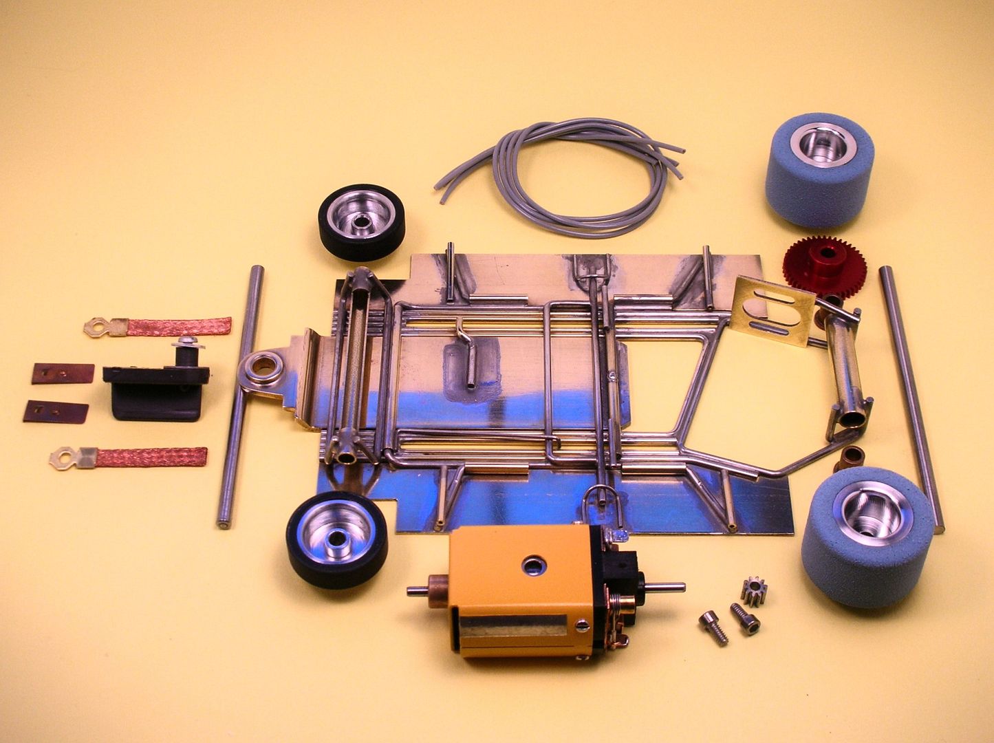
Onward!
Rick Thigpen
Check out Steve Okeefe's great web site at its new home here at Slotblog:
The Independent Scratchbuilder
There's much more to come...
Posted 05 July 2016 - 08:40 PM
Hi Rick,
I don't post much, but I have greatly admired your (and others') beautiful and thoughtful work on this blog for years. I would guess that through this very health conscious time, you have received great support from family and friends, but the creative endeavors get put on hold (even though they can provide a distraction and some sense of order). So what I am saying is, it's good to have you back doing one of the things that you (and us) enjoy most.
Thanks for all of the great work.
Posted 06 July 2016 - 02:40 AM
Hi Rick,
Very glad to hear that news. Been wondering why we haven't heard much from you, and now I know.
Hope everything goes well; I'm afraid all of us of this generation are a little too familiar with the medical world these days... hang in there, we're all behind you.
Onward and upward!
Don
Posted 06 July 2016 - 08:52 AM
Posted 06 July 2016 - 02:47 PM
Onward, yes ![]() Stay away from doctors
Stay away from doctors ![]()
Paul Wolcott
Posted 09 July 2016 - 06:22 PM
Thank you guys. ![]()
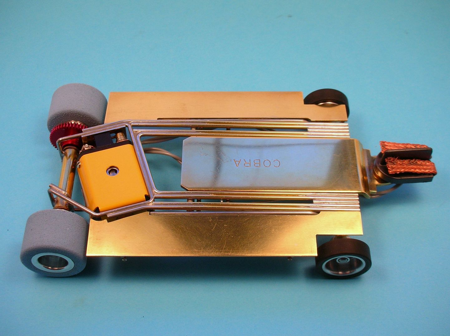
Howie's tribute racer hit the track today.....my little track anyway. ![]()
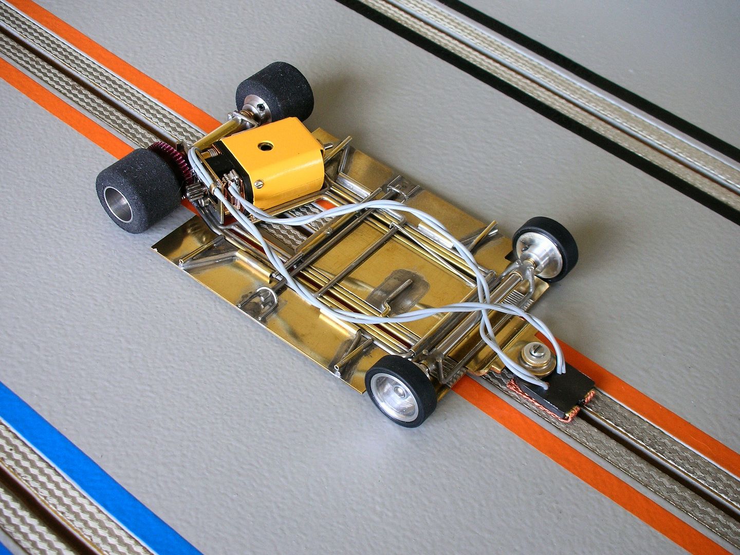
Here are some pics with it's blue "display" tires:
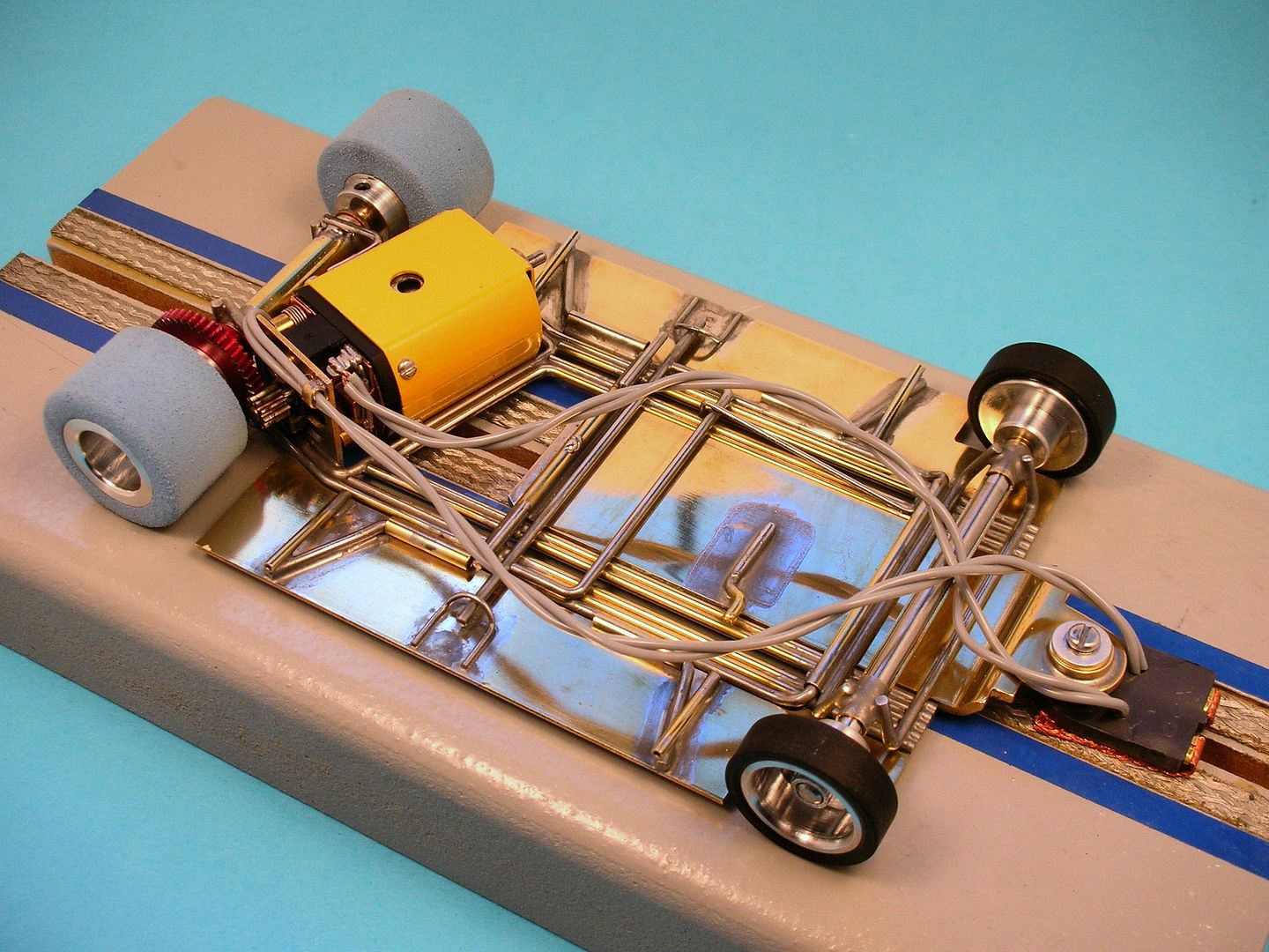
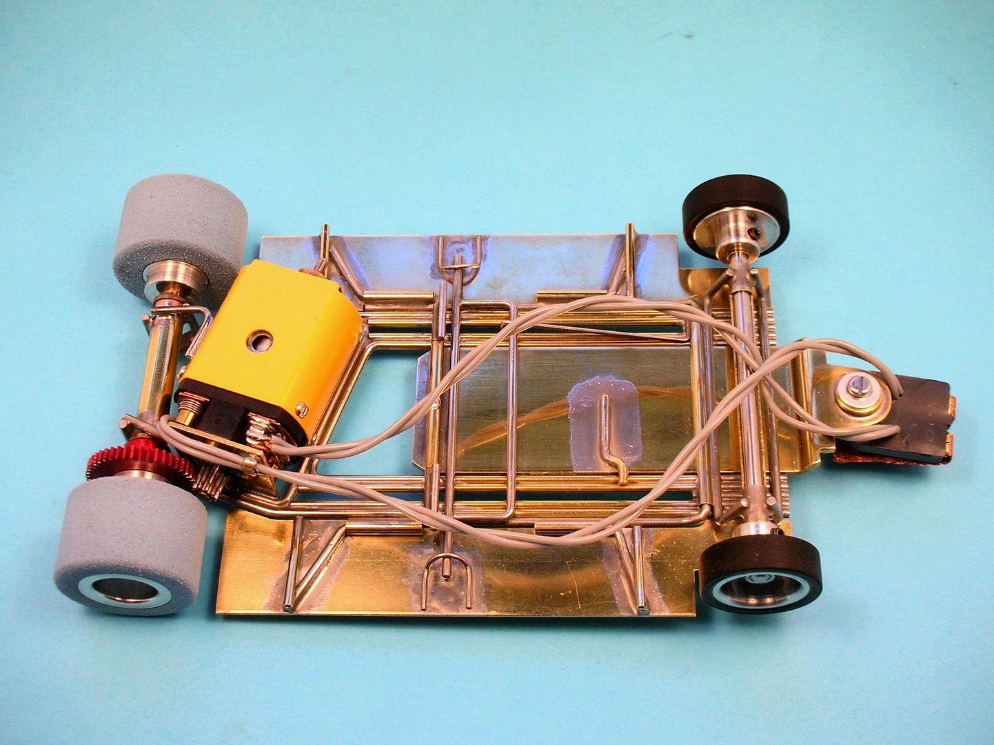
The motor is soldered in with a simple "L-brace". I can't route the lead wire on top of the motor. The body needs to sit all the way down on the motor:
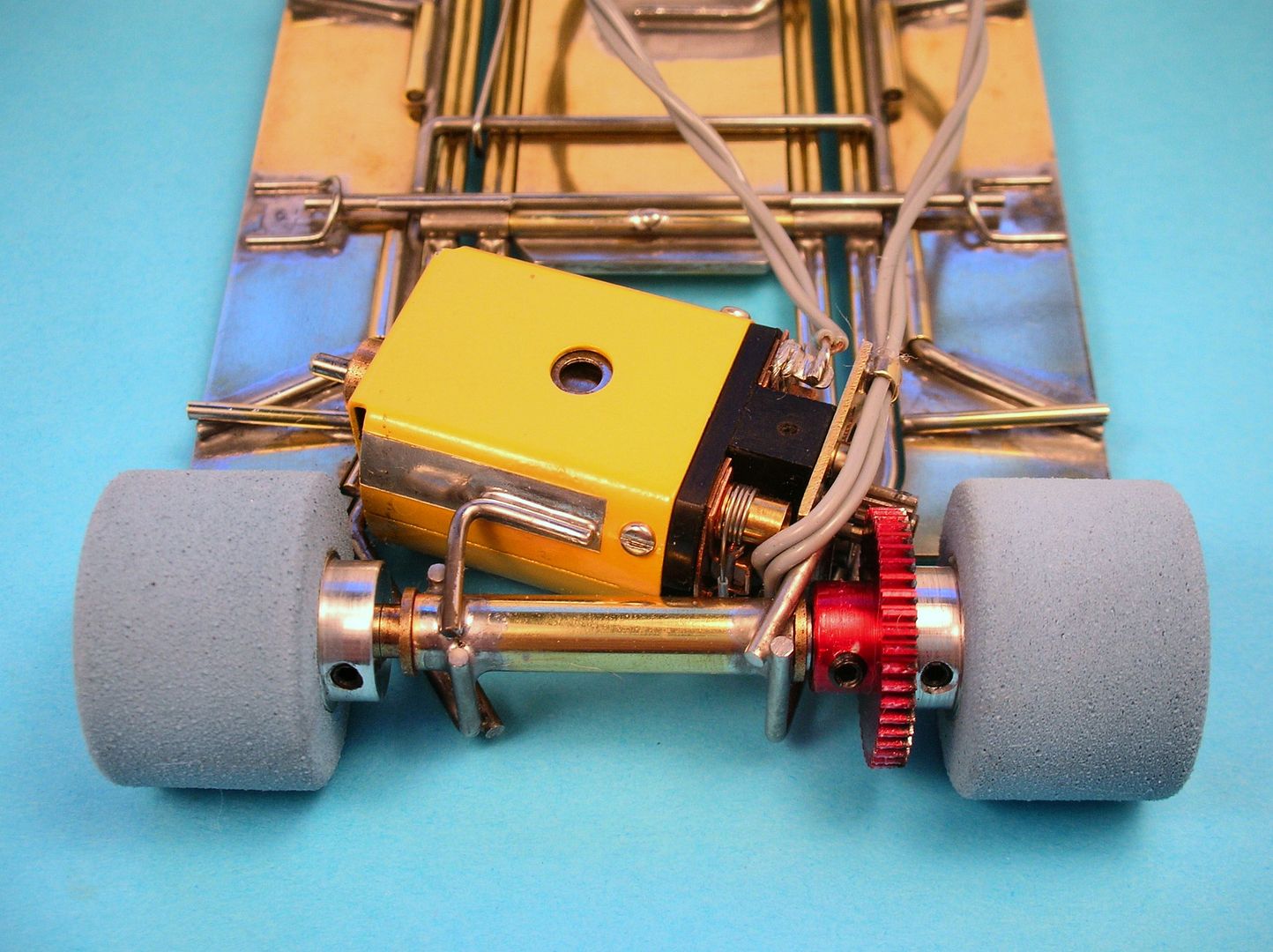
I've seen period pictures of racers running the wires along the back of the motor (keeping them in place with tape) and up the left side of the car. The picture of Howie's car shows his wires all on the right side so........
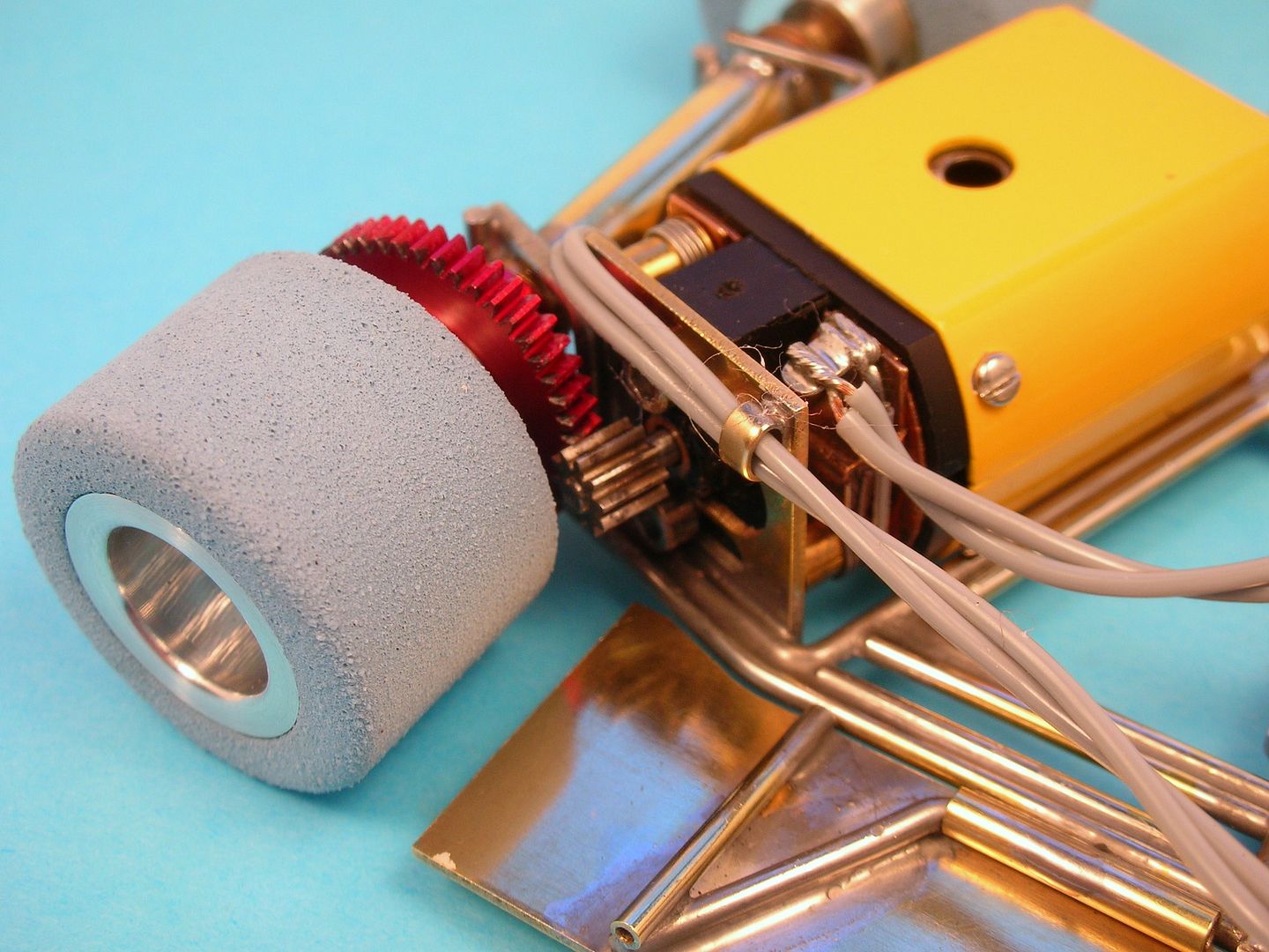
............I made a little wire retainer from flattened 1/8" tube and soldered it to the motor bracket.
Next up, I need to get a body on it and send it to Rodney for proper setup at Eddie's Slot Car World. ![]()
Rick Thigpen
Check out Steve Okeefe's great web site at its new home here at Slotblog:
The Independent Scratchbuilder
There's much more to come...
Posted 09 July 2016 - 06:41 PM
Rick,
Glad to here everything's good! Great to have you back building ![]()
I have learned a lot from you on building and history from your posts... Keep up the good work !
Ken
Posted 10 July 2016 - 12:34 AM
Too cool for words.
![]()
Steve King
Posted 10 July 2016 - 08:10 AM
Very strong looking and ultra-SANO ![]()
![]()
![]() I can just tell looking at it, the handling is going to be a home run.
I can just tell looking at it, the handling is going to be a home run.
Paul Wolcott
Posted 10 July 2016 - 11:18 AM
Posted 10 July 2016 - 06:14 PM
I have one of those 1-hole Mura 16D cans. Mine came in a Grp. 20 kit bought in 1969 or 70 at the original Modelville Hobby in Framingham, MA.
Posted 10 July 2016 - 06:33 PM
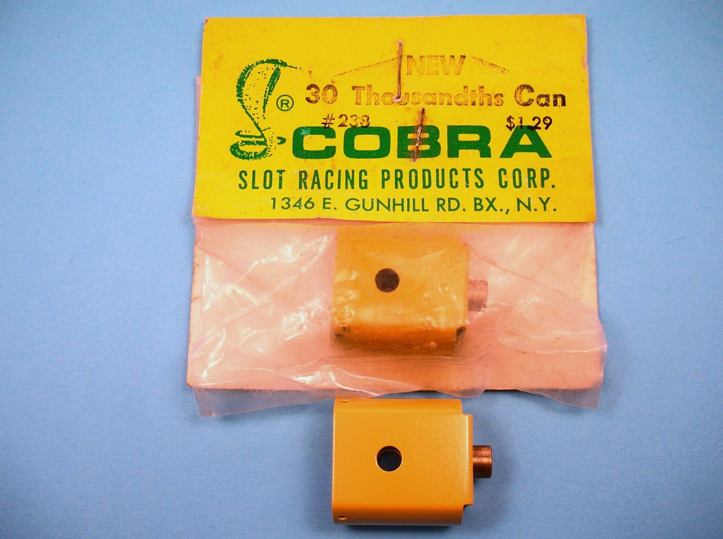
The Mura 1-hole can is cool. ![]() When Sandy Gross sent along a Cobra version I couldn't wait to get it into Howie's car:
When Sandy Gross sent along a Cobra version I couldn't wait to get it into Howie's car:
Rick Thigpen
Check out Steve Okeefe's great web site at its new home here at Slotblog:
The Independent Scratchbuilder
There's much more to come...
Posted 11 July 2016 - 10:48 AM
Looking good, Rick ![]()
I'm really happy everything, including the motor, seems to have fit as intended. I was a bit nervous about that; those clearances are fairly close.
That lead wire retainer mounted on the motor bracket is very clever... I've never seen anyone else do that. I may have to steal that idea at some point! ![]()
Steve Okeefe
I build what I likes, and I likes what I build
Posted 11 July 2016 - 01:10 PM
Thanks Steve.
I'm really happy everything, including the motor, seems to have fit as intended. I was a bit nervous about that; those clearances are fairly close.
That's for sure Steve. I like a "snug" fit. It shows careful craftsmanship. It's hard to tell form the picture below but there is a bit of clearance around the motor:
Everything went together just fine. I did grind a little clearance flat on the motor box for some extra room for the end bell screw.
Rick Thigpen
Check out Steve Okeefe's great web site at its new home here at Slotblog:
The Independent Scratchbuilder
There's much more to come...