
Josh Crutchfield built this JW stock car kit, DHMI guide tongue, Chicagoland Bracket.
Thanks Josh!
Sent from my iPhone using Tapatalk

Posted 03 December 2019 - 05:36 PM

Posted 27 December 2019 - 01:17 PM
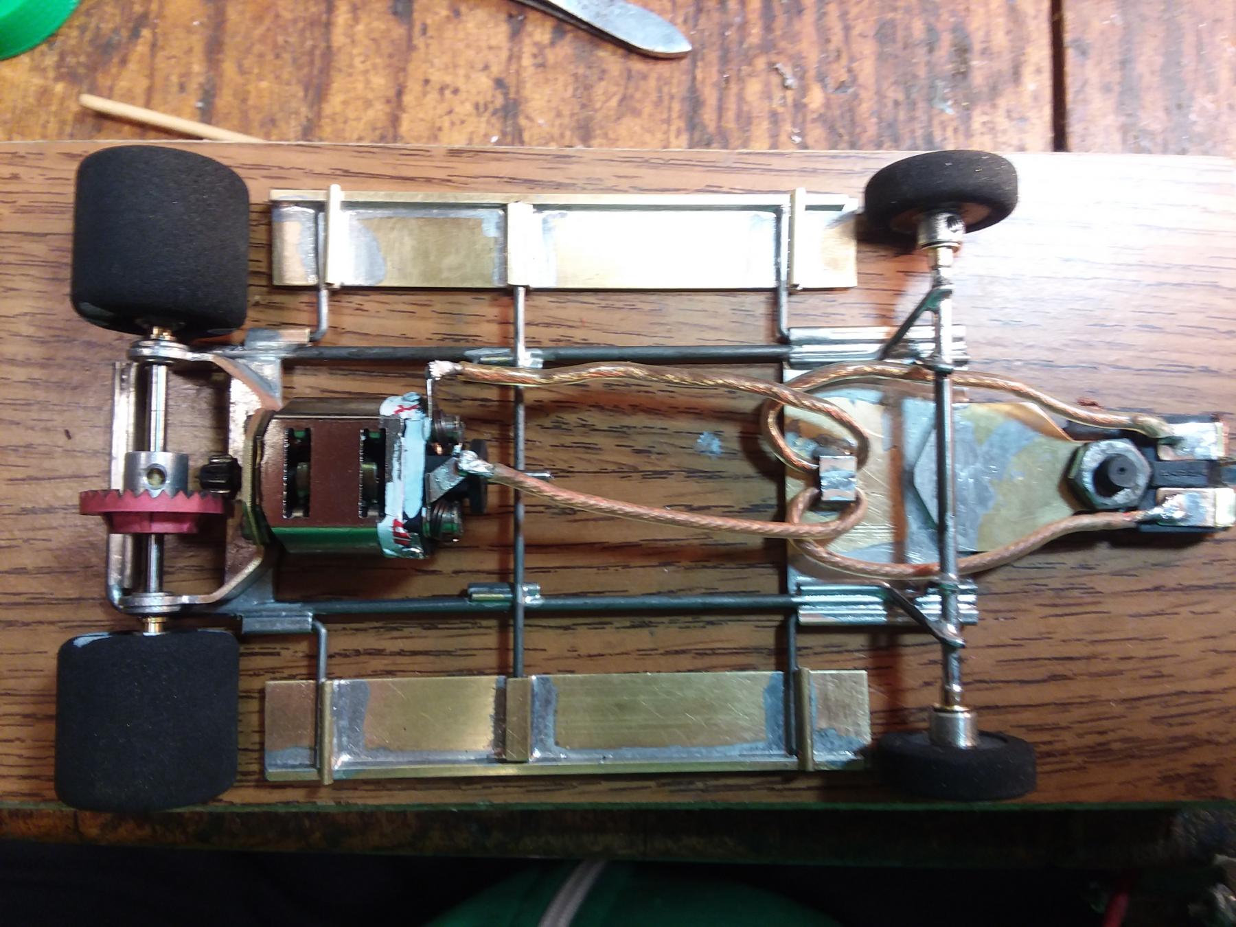 Had a few Mossetti motor brackets kicking around, compliments of a friend. Man they take a lot of work to get close to being usable. Started out as a squidopussy and then realized this bracket is to wide at 1.30 inch to build with that many rails so decided to make it an .073 MONORAIL! Still waiting for its steel guide tongue if it is worthy.
Remember the Steube bar! (ask Raisin)
SUPPORT YOUR LOCAL RACEWAY!!
"The denial of denial is the first sign of denial." Hank, from Corner Gas
"Death before disco!" Wanda from Corner Gas
Nelson Swanberg 5618
Peace be with all of us and good racing for the rest of us.
Have controller. Will travel. Slot Car Heaven
Posted 27 December 2019 - 06:15 PM
If you used a standard piano wire, it's probably .078 (2mm) rather than .073. if your current guide tongue is .032 brass, it's gonna bend. Steel will be a big improvement as will .063 brass. Let us know how this chassis handles for you.
Posted 28 December 2019 - 12:20 AM
I did mean .078. Got it down to 4.344 on the Downriver King track so it is half a second of the pace but it feels very stable. I think it has potential. It will get a steel guide tongue and and hopefully a better motor for further evaluation. I gave up on brass guide tongues long ago but that was the only one I had.
Remember the Steube bar! (ask Raisin)
SUPPORT YOUR LOCAL RACEWAY!!
"The denial of denial is the first sign of denial." Hank, from Corner Gas
"Death before disco!" Wanda from Corner Gas
Nelson Swanberg 5618
Peace be with all of us and good racing for the rest of us.
Have controller. Will travel. Slot Car Heaven
Posted 27 January 2020 - 02:33 AM
I've been building since the Sano XIII after speaking at length with a bunch of the more prolific chassis builders, intending to design/build my first Retro Can Am for a King track.
This was a difficult build, incorporating a bunch of features I had been saving for a while, all crammed into one design (aren't we supposed to change just one thing at a time) but I was just "going for it". Designed, as most others, using SolidWorks CAD. I will add some CAD images after posting phots of the car right off the track from its first race in the Rocky Mountain Retro Racing Association (RMRRA) yesterday (save for a swabbing-up of the pesky "rubber dust").
The emphasis was on making it 1) near the minimum legal weight, 2) the lowest possible center of gravity, 3) copy one of Bartos' chassis rail "schedules" (four rails of .047 on each side of center) as a starting point and 4) has to be "Colorado Tough" for reliability.
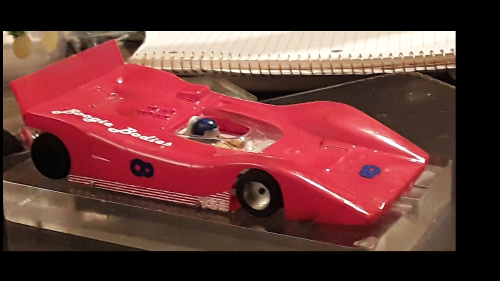
Original test body (Parma Lola) was used as this Boogie "Race Prize" body was much lighter than any Ford G7A (you call them Ti 22's) than I had ever mounted. Another trick I liked (seemed to eliminate some overall and up high weight) was to use the parent body material for the spoiler, making a bend about 1/8 inch below the top edge at the rear and small stapling it at the outer edges, creating that unsupported scooping curvature at the center to bleed off air at high speed while the outer edges were supported vertically. I think I read Noose stating that parent material of the body can be used as a spoiler as long as it is flat at rest (it is!).and, otherwise, dimensionally correct.
Also, I chose the number "infinity" just because it was already on the sticker sheet ... If 0 is a number, then infinity is, too!
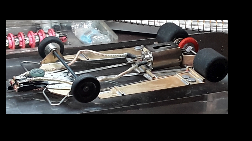
I used my own design and fabricated .040 motor bracket (same as first used on CAphXIII and since) with four bends, similar to Mossetti's Retro Can Am kit (it appears we came up with a similar design separately - I used Finite Element Analysis to optimize mine in 2013), bevel gear relationship (motor shaft axis points straight at the center of the rear axle). This violates goal number 2 but only puts the rear of motor about .030 above chassis bottom plane (nose of motor is flush), raising the CG of the motor only have of the rise (about .015). I think that is an acceptable compromise of goal 2) in order to get the mechanically best gear mesh for least power transmission losses (we do not have enough power with the JK RH to give up ANY).
I designed up the front bracket to use .040 brass with two vertical front axle uprights. The axle is located inside motor collars (comes with the JK fronts) as a bushing surface and is not soldered in because it it captured by the front tires.
A Chicagoland hardened steel guide tongue is the only way to go. The rails are .007 proud of the top of the .047 front pan and were ground flush so the guide tongue would lay flush. The underside of the guide tongue retains the rails in the precision slots.
Note that the front pan also has four outward bent tabs, two forward and two aft of the front tire. Each has .055 diameter holes to restrain the formed .055 front "bumper" wire (the rails are "captured" by the tabs) to facilitate goal 4). The aft ends of the bumper wire pass thru the aft tabs and are parallel to the front diverging outer rails. A square tube is soldered onto the forward ends of the .025 bat pans to allow a limited and unrestricted up, down and lateral limited motion. So far, it is facilitating goal 4).
The center 3 rails are tapered converging to the center moving forward. The outermost of the three rails is one piece kicking up behind the rear axle and spans behind the gear (soldered to the inside of the motor bracket uprights), the middle rail kicks up (near) 90 degrees and is soldered on to the rear face of the motor mount outside of the screw heads for longitudinal stiffness (as separate rail on each side) and the innermost rails are individual and span from under the guide tongue past the motor bracket to the back.
The rail that splays diverging outward to the front is one rail, spanning past the motor bracket connecting to the other side behind the other rails. The forward ends kick out 90 degrees into the front pan to "lock it in" to a notch on both sides of the front pan, milled by hand with a makeshift carbide side cutter in a Dremel.
There is an aft "clicker" used to add weight to bring it up to legal minimum in the lowest possible way per goal 2) to avoid adding lead mass to the top of the pans and to shift the total mass aftwards, CG measured at a consistent value of 2.00 +/- .050 for all of my previously good handling chassis (measured to be the same with other's good handling chassis, adjust to taste).
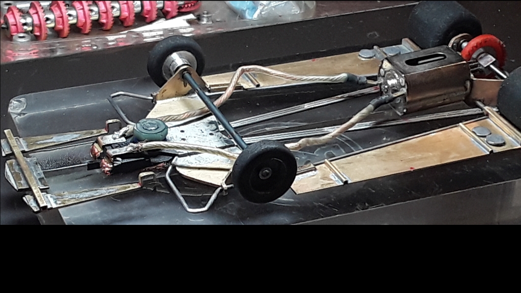
This image shows the clicker removed from the chassis.
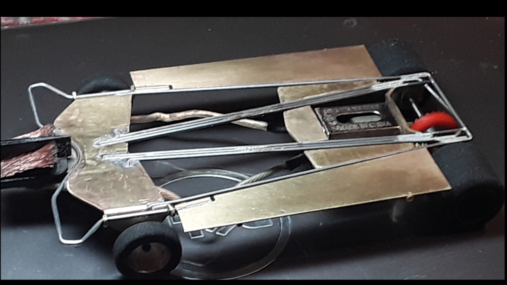
This image shows the underside of the chassis with the clicker in place to show detail of how the diverging single and converging triple rails are embedded in the front pan (the outer of the triple rails has a 90 degree kick-out trapped fore-aft by the front pan), all to satisfy goal 4). I made the pieces that fit between the rails out of .040 (not an uncommon thickness of brass as 1mm is .03934 so I think this is 1mm stock, got it from McMaster-Carr years ago) which works out real well because the rails are .047, providing a margin of .007 that the clicker will always be above flush with the bottom plane of the chassis. Odd that I still saw a little bit of arcing on the RF corner of the underside...
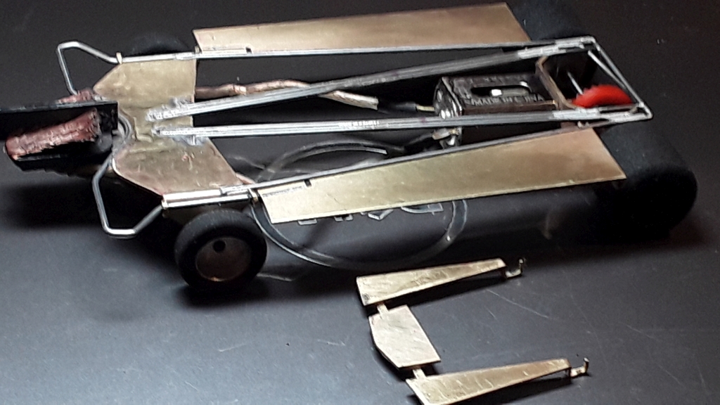
This underside view shows the clicker removed. The brass is formed at the aft end to rest on the square tubing that supports the aft end of the bat pans.
This is also a good view of the single piece bumper rail and how it is affixed. The edges don't contact an abrupt sharp edge on either side of the guide flag but, instead, a rolling surface. It is easily adjusted to maintain the .015 clearance at the front when the car is supported only by the front tires. Unmolested .055 wire is a good choice because if the outrigger portion in fore of the front tires ever contacts the track, then it does so with a round tangent section of the wire so that it doesn't scrape the track surface like the leading edge of a piece of brass sheet (I should have stated goal 5), do no harm to the track in consideration to the track owners and all racers, including myself).
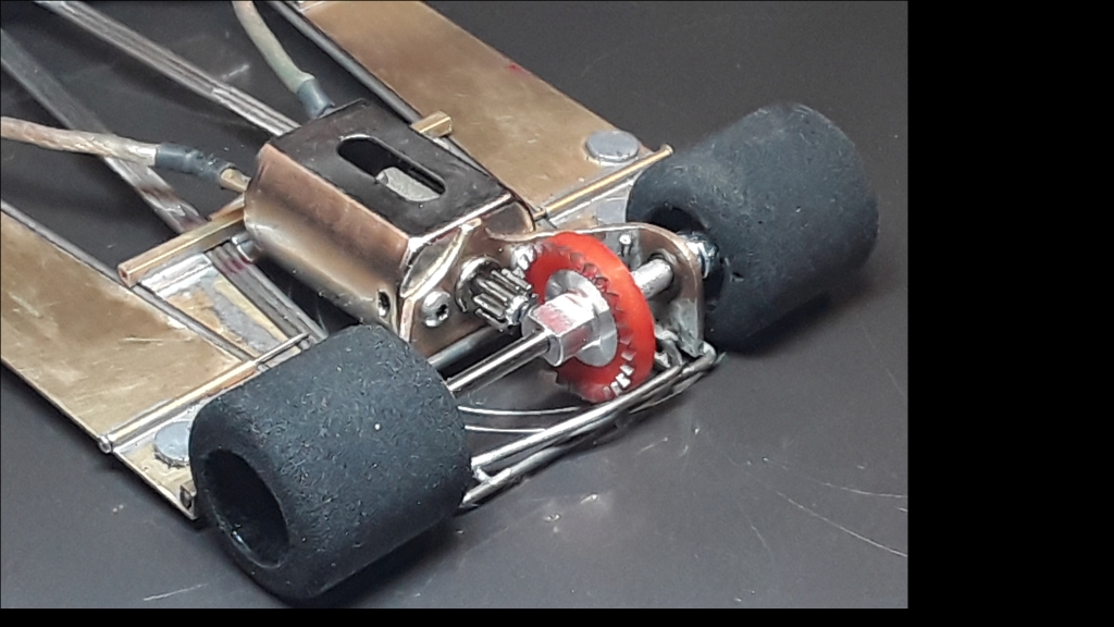
This aft end view shows the 90 degree kick-up of the middle rails to add stiffness. It also shows a full width lateral .055 rail thru holes in the motor bracket, in tight to the aft motor mount face. These were precision located for square tubes soldered directly on top of the .025 thick bat pans providing robust goal 4) limited fore-aft & up-down motion complimenting the perpendicular forward bat pan mounts mentioned earlier. There is no chance of a drooping pan without a very significant shunt in a direct shot downward on the pan; very unlikely. Bat pan hinges breaking off from a steel rail is, sadly, still a problem when assisted into a wall as a "rider"; pretty much ends your race - see goal 4).
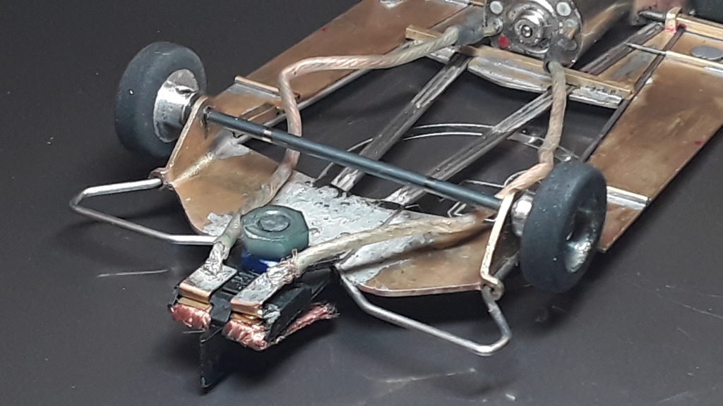
This view shows the details of the front end. Note the damage to the front guide clip in one of the shunts from yesterday - sometimes you luck out and finish anyway. That's now three races on that guide flag but, clearly, it needs to be changed.
Also, I tend to put a plastic nut on the top of the post to spread out the load to support the nose of the body - it, at least, keeps the center of the body from dragging hard and will help a bit with the outer front edges of the body most of the time, in my opinion. I put a piece of clear packaging tape on the underside of the body above the nut to make it more slippery so as to not restrict the lateral "give" of the body and to protect the paint finish. Remember, it is good engineering practice to make every part do at least TWO jobs if you can for mass efficiency.
I really wanted to share this because the car is working well, drives like a very light car and corners flat like a low CG car. It is the fastest thing in my box, consistently a bit faster in all track conditions (so far) than the Bartos-built car that I have been using as a standard. It is also much faster than the much heavier "Hillclimb / Grandstand" track cars I have been building up to now.
I'm pretty sure someone will see something that they think is "controversial" - it seems it has always happened when I have posted pictures of my builds in the past. In any case, it may spark some new avenues of thinking for others to try.
Sorry about the nerf. "Sorry? Sorry? There's no apologizing in slot car racing!"
Besides, where would I even begin? I should probably start with my wife ...
"I don't often get very many "fast laps" but I very often get many laps quickly." ™
The only thing I know about slot cars is if I had a good time when I leave the building! I can count the times I didn't on one two three hands!
Former Home Track - Slot Car Speedway and Hobbies, Longmont, CO (now at Duffy's Raceway), Noteworthy for the 155' Hillclimb track featuring the THUNDER-DONUT - "Two men enter; one man leaves!"
Posted 27 January 2020 - 02:50 AM
Help me, Cheater, It appears it posted 4 times!
Sorry about the nerf. "Sorry? Sorry? There's no apologizing in slot car racing!"
Besides, where would I even begin? I should probably start with my wife ...
"I don't often get very many "fast laps" but I very often get many laps quickly." ™
The only thing I know about slot cars is if I had a good time when I leave the building! I can count the times I didn't on one two three hands!
Former Home Track - Slot Car Speedway and Hobbies, Longmont, CO (now at Duffy's Raceway), Noteworthy for the 155' Hillclimb track featuring the THUNDER-DONUT - "Two men enter; one man leaves!"
Posted 27 January 2020 - 06:30 AM
Boy AJ - you wanted to make sure you got this out there...lol
Looks great!!!!
Jeff Strause
Owner, Strause's Performance Racing (SPR)
USSCA 2016 4" NASCAR Champion & 4 1/2" NASCAR Champion & Retro Can-Am Champion
USSCA 2017 All Around Champion
USSCA 2019 All Around Champion
Posted 27 January 2020 - 08:27 AM
glueside, on 27 Jan 2020 - 11:30 AM, said:
Common issue.Boy AJ - you wanted to make sure you got this out there...lol
Looks great!!!!
A. J. Hoyt, on 27 Jan 2020 - 07:50 AM, said:
Fixed.Help me, Cheater, It appears it posted 4 times!
Mike Swiss
Inventor of the Low CG guide flag 4/20/18
IRRA® Components Committee Chairman
Five-time USRA National Champion (two G7, one G27, two G7 Senior)
Two-time G7 World Champion (1988, 1990), eight G7 main appearances
Eight-time G7 King track single lap world record holder
17B West Ogden Ave., Westmont, IL 60559, (708) 203-8003, mikeswiss86@hotmail.com (also my PayPal address)
Note: Send all USPS packages and mail to: 692 Citadel Drive, Westmont, Illinois 60559
Posted 27 January 2020 - 08:49 AM
Posted 27 January 2020 - 08:59 AM
Mike Swiss
Inventor of the Low CG guide flag 4/20/18
IRRA® Components Committee Chairman
Five-time USRA National Champion (two G7, one G27, two G7 Senior)
Two-time G7 World Champion (1988, 1990), eight G7 main appearances
Eight-time G7 King track single lap world record holder
17B West Ogden Ave., Westmont, IL 60559, (708) 203-8003, mikeswiss86@hotmail.com (also my PayPal address)
Note: Send all USPS packages and mail to: 692 Citadel Drive, Westmont, Illinois 60559
Posted 27 January 2020 - 11:05 AM
OK, a smaller post, the promised SolidWorks CAD images.
This is the top view of the rails with motor bracket, formed front pan and guide tongue.
Top view with bat pans showing attachment / motion limits. It didn't need the end caps; it fully captured and not going anywhere outside of legal width with only the constraint of the fore and aft square brass tubes! The shaker motion of the bat pans is very small (per current practice for nice King tracks) but it rattles like a tambourine when clean! That's my test for every intended motion to ensure nothing is bound up.
Underside with bat pans. Note the aforementioned lock-in of the diverging (to front) rails and the outermost converging triplet rails in the front pan! Bending and fitment is getting easier to do with practice ...
Detail of front pan with Chicagoland hardened steel guide tongue (Mike, you make great stuff!). I don't know how people make stamped brass guide tongues (alone) work (remember goal 4) or keep the outer planes parallel when adding a steel reinforcement to a formed brass tongue!?! Too tough for my fabrication skills!
Note the front pan outward bent tabs to hold the formed bumper wire in place. It should be plain now how the ends constrain the fwd end of the bat pans. Remember, for mass efficiency, everything should do two jobs! It's only soldered behind the guide flag so it will bend and flex back in an impact.
This was a hard build! I swore I would never make another one but, the way this runs, I'm glad I made a second set of parts.
Sorry about the nerf. "Sorry? Sorry? There's no apologizing in slot car racing!"
Besides, where would I even begin? I should probably start with my wife ...
"I don't often get very many "fast laps" but I very often get many laps quickly." ™
The only thing I know about slot cars is if I had a good time when I leave the building! I can count the times I didn't on one two three hands!
Former Home Track - Slot Car Speedway and Hobbies, Longmont, CO (now at Duffy's Raceway), Noteworthy for the 155' Hillclimb track featuring the THUNDER-DONUT - "Two men enter; one man leaves!"
Posted 27 January 2020 - 11:50 AM
More insight into using CAD. I found that printing the parts and flat patterns on a single sheet A-sized drawing works on any home printer after you find the proper scale adjustment to print full size. All small home printers are accurate and repeatable within .002 in my experience so they are plenty accurate to make patterns and wire shapes.
Using them as templates, I was able to bend all of the .047 rails and the .055 front bumper on the first try but that is with years of practice. The hardest part is getting it to lay flat once it matches the printed pattern. I have tried the wire bending tools and I still prefer just marking the bend with a Sharpie (allowing for bend radius) and "going for it" with a great set of compound needle nosed pliers that Mike Swiss pointed out years ago on SlotBlog.
Nelson has often said that you can build three cars at the same time and assemble them with identical parts but they will all have a different "personality" on the track. As a linked corollary, he also says that you can't trust a single build because it might be a "magic" car and a duplicate might be a wrist-slashing disappointment. If it isn't, you might be on to something.
To that end, I always make at least two sets of patterns on my drawings, fabricate two sets of front pans and motor brackets (at least) and use the best ones. Don't ever use parts that cannot be made tight with a couple of thousandths of what you intended.
The Sheet Metal feature in SolidWorks makes very nice flat patterns for the motor bracket and front pan. After printing the A sized drawing on an 8 1/2 x 11 sheet of Avery address label (sticky back) paper, I cut out the patterns, stick them to the brass. Then I go "old school" and sandwich the part between two hardened stainless blocks (with straight, small edge break) along the bend line in a vice and bend it over with a small hard plastic mallet, then finish the bend with a standard sheet metal hammer to get it nice and square. There is no spring-back this way.
Detail of "spare" front pan flat pattern (dashed line is the bend line, very nice "cross-hairs" for the drilled holes) and a formed rear bracket. The pattern sticker stays on for the entire fabrication process, checking the holes for proper location as I go. I use a sequence of holes and check the locations for "parallel to motor mount face" and lateral location of the uprights from motor mount holes.
The motor bracket is formed but the front pan shows that I have already made the "harder" Dremel cuts (to facilitate forming) and drilled the holes while it is flat - much harder to hit that target AFTER it is formed! All of the holes get drilled out progressively bigger while "spotting" it with a punch on the cross-hairs and checking it in relation to the printed final hole circle.
Note the flat pattern of the lateral tabs for the bumper wire; needless to say, this was tricky but I have some good tricks and the second one (yes, it is warranted now) will go MUCH faster.
Sorry about the nerf. "Sorry? Sorry? There's no apologizing in slot car racing!"
Besides, where would I even begin? I should probably start with my wife ...
"I don't often get very many "fast laps" but I very often get many laps quickly." ™
The only thing I know about slot cars is if I had a good time when I leave the building! I can count the times I didn't on one two three hands!
Former Home Track - Slot Car Speedway and Hobbies, Longmont, CO (now at Duffy's Raceway), Noteworthy for the 155' Hillclimb track featuring the THUNDER-DONUT - "Two men enter; one man leaves!"
Posted 27 January 2020 - 12:18 PM
While cleaning up the work area, I spotted a chassis with very elaborate cuts, the most difficult are the Dremel disc cuts along long straight edges. This provides more insight into the CAD flat pattern sticker method.
I made three of these "nested" sticker sets of the CAphXVII and cut all three sets to this level with ONE DREMEL DISC! Part of the credit belongs to the brass because it was a "mirror finish" (one side) 3/4 hard .031 thick sheet from McMaster-Carr. (I can't find it there now but it might be available again, I bought a 1' x 2' piece at that time). I thought a harder brass might be the better choice for this CAphXVII design, the first time I used the small tab with the hole in it. It adds a level of robustness because the wire going thru it cannot break off due to a failed solder joint of steel to brass.
The 3/4 hardness made it "cut like buttah", never gummy or "grabby". I cut it on a piece of oak or maple precision milled hardwood and pushed the sheet into the disc like a top-side table saw and it just made powder while it glided over the hardwood surface!
This shows the mirror finish underside and the long cuts that were made. Note that they are interrupted so the sheet has some "attachment" integrity while cutting. The are carefully finished when the individual parts are separated with shorter (but similar care) cuts are made.
I was pleasantly surprised at how well it formed using the "old school" method mentioned in the previous post. I was afraid that i3/4 hared might crack with a 90 degree bend!
Also, note the very close cuts made at the aft end of the pan that goes under and fills in the 4-sided motor bracket flush with the bottom of the chassis. These were made just because I was "on a roll" (and already covered with brass powder dust). I cut the little comb tines off at their bases to make my (signature half a Ford oval) shape to clear the rear gear. I have found that this is a very fast way to cut out a bigger shape, cleaned up later using a variety of stone Dremel tools. Raisin will appreciate this as he probably taught it to me. The Ford oval is important!
As I stated, I made three of these at one time, built one, it was very, very fast (and the mirror finish was very pretty! You could count your nose hairs in the reflection, if so inclined) but never spectacularly fast, like some of the cars I raced against. You can't see the mirror finish in the second pic because it is electro-polished, chemically sealed and then a piece of clear adhesive plastic sheet is on that side to protect it for shipping (came that way from McMaster-Carr). I use it sparingly now.
The car has been crashed a bunch of times and never bent badly so I built the second one for Nelson, a very good "go to" car for its time and a nice "show piece" in the box, of course, bottom side up. I forgot about this third one until it re-appeared during the CAphXXI build.
Sorry about the nerf. "Sorry? Sorry? There's no apologizing in slot car racing!"
Besides, where would I even begin? I should probably start with my wife ...
"I don't often get very many "fast laps" but I very often get many laps quickly." ™
The only thing I know about slot cars is if I had a good time when I leave the building! I can count the times I didn't on one two three hands!
Former Home Track - Slot Car Speedway and Hobbies, Longmont, CO (now at Duffy's Raceway), Noteworthy for the 155' Hillclimb track featuring the THUNDER-DONUT - "Two men enter; one man leaves!"
Posted 27 January 2020 - 12:40 PM
Just one more post because I was talking about Dremel disc failures (follow-up to Dremel disc cutting seems appropriate in the Scratchbuilding forum).
While still teenagers learning and racing together, Nelson, Raisin and I (Team Bugaloo) were always chiding each other about breaking discs, more often when setting the Dremel tool on the table than while cutting, as I recall.
Most of the time, they shatter into a number of pieces that distribute themselves into your face (safety glasses ALWAYS at a minimum!) or onto the table or floor where they are highly trained to blend in and/or hide the really small valuable parts during final assembly or adjustments.
I had to take a picture of this failure:
Note the odd "volcano" funnel shape near the attachment to the mandrel. Yes, there was the normal abrasive washer slug still under the mandrel screw head.
But this is NOT the Holy Grail "unicorn" "To Dream the Impossible Dream" disc failure:
This is it! Anyone ever had this happen? Maybe I can super glue this back onto the remaining abrasive washer under the screw head and get just one more cut? ... It seems this failure may be unimaginably dangerous! Can't believe it didn't shatter where it landed! That's why it is the unicorn!
Sorry about the nerf. "Sorry? Sorry? There's no apologizing in slot car racing!"
Besides, where would I even begin? I should probably start with my wife ...
"I don't often get very many "fast laps" but I very often get many laps quickly." ™
The only thing I know about slot cars is if I had a good time when I leave the building! I can count the times I didn't on one two three hands!
Former Home Track - Slot Car Speedway and Hobbies, Longmont, CO (now at Duffy's Raceway), Noteworthy for the 155' Hillclimb track featuring the THUNDER-DONUT - "Two men enter; one man leaves!"
Posted 28 January 2020 - 08:49 AM
A J that chassis is a unique creation. Thanks for the insights into your methods for creating it and parts in general. It is good to hear that the chassis is working well so far and I hope the second one is not a disappointment.
I have one question not related to the chassis. In your introduction you mentioned the Ford G7A and the TI22 calling them the same body. I know of no connection between the two. If you could please, what is the connection?
Posted 28 January 2020 - 11:07 AM
Just a non-conformist and a Ford guy. I saw the Ford G7A race at the Michigan International Speedway Can Am race and painted up a Ti-22 body with its paint scheme because the bodies looked similar enough. The Agapiou brothers even ran Ti-22 side dams in a later configuration so it is a case of "marque appropriation". I apologize to anyone who might be offended (political correctness and all that...). Enough thread drift ...
Sorry about the nerf. "Sorry? Sorry? There's no apologizing in slot car racing!"
Besides, where would I even begin? I should probably start with my wife ...
"I don't often get very many "fast laps" but I very often get many laps quickly." ™
The only thing I know about slot cars is if I had a good time when I leave the building! I can count the times I didn't on one two three hands!
Former Home Track - Slot Car Speedway and Hobbies, Longmont, CO (now at Duffy's Raceway), Noteworthy for the 155' Hillclimb track featuring the THUNDER-DONUT - "Two men enter; one man leaves!"
Posted 24 February 2020 - 09:47 PM
Posted 03 March 2020 - 10:55 AM
Upfront slot cars, on 25 Feb 2020 - 02:47 AM, said:
Justin , excellent work ! Maybe a little soft but you can always add rails to it. Please let us know how it runs. What type of track ? Again, super nice work!
Posted 18 April 2020 - 08:34 AM
Hello,
Since I have restarted slotracing at RetroTokyo from 2018, I have been making many chassis for myself and fellow customers.
Here are some of them.
My original separable chassis design.
Not only easy to maintain, repair and rebuild, but also run fast on the track.
Jeff Bonanno won 3rd place at 2019 Retro Palooza GTC-FK using this one.
More builds.
Complete RTR for a Tokyo racer. Body paint by Morio Hashimoto.
Conventional light-weight CanAm Plus chassis with tension rods for the vertical stiffness.
Quite effective, but this needs delicate tensile adjustment.
Stay Home, Build Chassis......
Posted 18 April 2020 - 03:48 PM
Very nice builds Hisatsugu San! Nice design with the separations possible for both F-1 and Can Am.
You're are great too Matt. Love the heavyweight one for a Retro Nascar especially!
Posted 18 April 2020 - 06:02 PM
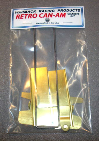
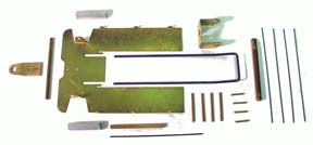
Just for laughs, below are pictures of the chassis that JK copied and began producing in 2007, the Warmack chassis kit that helped quite a few racers to get into Retro Racing in California, where it was born in 2006. Still one of the best handling Retro Can-Am cars I have ever driven, and nothing fancy about it...
Philippe de Lespinay
Posted 18 April 2020 - 10:02 PM
It was the second chassis I have EVER built!! Bryan is the reason I'm in retro racing and building some of my own chassis. This kit was simple, easy to build-- and DOES handle just about as good as ANY of the new style chassis!! THANK YOU to Bryan for showing how to get started bending wire and soldering. You're the best!!